1
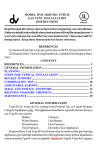
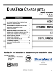
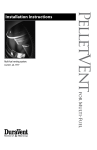
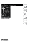
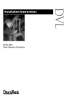
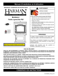
Round and Oval Type B GasVent
Systems for use with natural as or
liquid propane category I and draft
hood equipped appliances and
appliances listed to use Type B
Gas Vent.
Type B Gas Vent
Installation Instructions
A MAJOR CAUSE OF VENT RELATED FIRES IS FAILURE
TO MAINTAIN REQUIRED CLEARANCES (AIR SPACES) TO
COMBUSTIBLE MATERIALS. IT IS OF THE UTMOST IMPORTANCE
THAT TYPE B GAS VENT BE INSTALLED ONLY IN ACCORDANCE
WITH THESE INSTRUCTIONS.
NOTE:
Read through all of these instructions before
beginning your installation. Failure to install
as described in this instruction will void the
manufacturer’s warranty, and may have an effect on
your homeowner’s insurance and UL listing status.
Keep these instructions for future reference.
IMPORTANT:
Read through all of these instructions
before beginning your installation. Failure
to install this product as described in these
instructions will void the manufacturer’s
warranty, may create a fire or other safety
hazard, and may affect your homeowner’s
insurance and safety listing of your
appliance.
Dear Customer, Installer, or End User:
We welcome any comments regarding matters
pertaining to our DuraVent products.
We welcome any ideas, input or complaints
and I’ll make sure that someone responds
directly back to you.
Send your emails to:
[email protected]
If you are searching for tech support or product
Keep these instructions
for
future
information, please phone us at 800-835-4429.
C A ME R A -R E A DY L OG OT Y P E – UL MA R K F OR C A NA DA A ND T HE U.S .
reference. T hese Marks are registered by Underwriters L aboratories Inc.
Or email us at:
[email protected]
LISTED
MH6357
CONTENTS
Type B Gas Vent
Type b gas vent Installation Instructions
Round B Vent, General Information, Planning . . . . . . . . . . . . . . . . . . . . . . . . 4
Steps for Typical Installations . . . . . . . . . . . . . . . . . . . . . . . . . . . . . . . . . . . .7
Bucket Support . . . . . . . . . . . . . . . . . . . . . . . . . . . . . . . . . . . . . . . . . . . . . . .. . 11
Combination Cap . . . . . . . . . . . . . . . . . . . . . . . . . . . . . . . . . . . . . . . . . . . . . . . 11
Adjustable Elbows, Male and Female Adapters. . . . . . . . . . . . . . . . . . .. . . . 12
Relining Masonry Chimneys for use with Gas Appliances . . . . . . . . . . . . . . . 13
Troubleshooting. . . . . . . . . . . . . . . . . . . . . . . . . . . . . . . . . . . . . . . . . . . . . . .. .17
Maintenance . . . . . . . . . . . . . . . . . . . . . . . . . . . . . . . . . . . . . . . . . . . . . . . . . . 18
Oval B Vent, Installation Notes . . . . . . . . . . . . . . . . . . . . . . . . . . . . . . . . .. . .19
4-Inch Oval Installation in 2x4 Inch Stud Walls . . . . . . . . . . . . . . . . . . . . . . 22
5-Inch Oval Installation in 2x4 Inch Stud Walls. . . . . . . . . . . . . . . . . . . . . . 24
6-Inch Oval Installation in 2x6 Inch Stud Walls . . . . . . . . . . . . . . . . . . . . . . 26
Round B Vent
GENERAL INFORMATION
Type B Gas Vents are for venting listed Natural
Gas or Liquid Propane Category I appliances
only. The appliances listed below typically
(but not always) use Type B vent systems.
Boilers
Furnaces
Water Heaters
Unit Heaters
Room Heaters
Duct Furnaces
Floor Furnaces
Decorative Gas Appliances
DuraVent Type B Vent Systems may be used
on other gas-burning appliances, provided
the manufacturer of the appliance states in
their installation instructions that Type B-vent
is acceptable. Do not use Type B Vents
for Category II, III, or IV gas appliances.
Type B Vent shall not be used to vent flue
products from incinerators, combination gas/
oil appliances, oil-fired, or wood-burning
appliances. If there is a question about the
use of Type B Vents, contact the appliance
manufacturer or DuraVent’s Engineering
Department for further information.
PLANNING
1. Appliances. Carefully review the appliance
manufacturer’s installation instructions for
positioning the unit, any special venting or
connector requirements, and verify that it is
a Category I appliance or an appliance that
requires the use of Type B gas vent.
2. Placement. The placement of the vent
and fittings must be in accordance with Local
Codes, as well as accepted venting practices.
If more than one appliance is to be connected
4
to one venting system, the common vent must
be correctly sized. It is a good idea to make
a sketch of the proposed installation, labelling
the components you will need. Adjustable Pipe
Lengths are available to make up odd lengths.
Minimize the number of turns and lateral
runs, as the National Fuel Gas Code places
limitations on these. A 45° turn is preferable to
a 90° turn. The appliance reference material
should be consulted at this time, as well as any
Local Authority having jurisdiction. In most
localities, building permits are required for any
new appliances, or modifications to existing
venting systems.
3. Figures 1, 2, & 3 show examples of some
typical residential installations.
4. Clearance to Combustibles. A 1-inch
clearance (air space) to combustible
materials must be maintained, when using
DuraVent Round B-Vent, regardless of the
pipe diameter.
5. Combustion Air. Refer to appliance
installation instructions and local building
codes to ensure compliance with required
volume of combustion air for each appliance
installed .
6. Slope. If the venting system contains
lateral (horizontal) components, they shall be
positioned so they have an upwards slope
away from the appliance of not less than
1/4-inch rise per foot of run. (Horizontal
vent installed in attics, unconditioned area, or
between floors have further restrictions, please
consult your local building codes for specific
limitations.)
7. Termination Area. Examine the area where
the vent system will terminate. The height of
the termination above the roof is determined
by the roof pitch, and also it’s proximity to
adjacent walls or obstructions. Consult Table
2 for proper termination height requirements.
Vent pipe with 3”-12” diameter must terminate
HIGH WInD cap
DuRacap TOp
DOTTED L InES
SHOW pOSSIBLE
OFFSET In aTTIc
SpacE
STOR M
cOLLaR
cEILInG SuppORT /
FIRESTOp
SEE TaBLE 2
FLaSHInG
TOTa L
VEnT
HEIGHT
90° aDJuSTaBLE
ELBOW
B-VEnT TEE
B-VEnT
pIpE
WaTER HEaTER
cOnnEcTOR RISE
FIRESTOp
SpacE R
1 IncH MInIMuM
cLEaRancE
(aLL S IDES)
FuRnacE
cOnnEcTOR RISE
IncREaSER
WaTER HEaTER
WITH D RaFT H OOD
B-VEnT
Fan aSSISTED
FuRnacE
EncLOSuRE
1 IncH MInIMuM
cLEaRancE
(aLL S IDES)
LaTERaL
Figure 2
cEILInG SuppORT
/ FIRESTOp
VEnT c OnnEcTS
TO appLIancE
Figure 1
at least 2 feet higher than an adjacent wall
or obstruction, if it is within 8 feet. Vent pipe
with 14” or larger diameter must terminate
at least 2 feet higher than an adjacent wall or
obstruction, if it is within 10 feet.
8. Connector Rise. Plan a minimum of one
foot vertical connector rise coming out of each
appliance.
STEPS FOR TYPICAL
INSTALLATION
1. Location. Building Code requires the
appliance(s) to be located as close to the vent
as possible. After consulting the local codes,
appliance installation instructions and any
other applicable reference material determine
the optimum location for the appliance(s).
2. Penetration Point. Locate and mark the
center of the penetration point through the
ceiling or the wall. Refer to Step 3 or 4, as
appropriate.
5
Table 1
B-VENT WYE
B-VENT USED AS
CONNECTOR
45º / 60º
ADJUSTABLE
ELBOW
FURNACE
CONNECTOR
RISE
FAN
ASSISTED
FURNACE
1 INCH MINIMUM
CLEARANCE
(ALL SIDES)
TOTAL
VENT
HEIGHT
WATER HEATER
CONNECTOR RISE
DURA-CONNECT
FLEXIBLE SINGLE
WALL CONNECTOR
WATER HEATER
WITH DRAFT HOOD
pipe size
stock
framed inside
number
dimensions (x & Y)
of ceiling fig.4
support
3 inch
4 inch
5 INCH
6 INCH
7 INCH
8 INCH
10 INCH
12 INCH
1440
1441
1442
1443
1444
1445
1446
1447
6"x6"
7"x7"
8"x8"
9"x9"
10"x10"
11"x11"
13"x13"
15"x15"
LATERAL
Figure 3
EXISTING
JOISTS
EXISTING
SHEET
ROCK
Figure 5
CLAMP AND
HARDWARE
FRAMING MEMBERS
REQUIRED FOR
SUPPORT
Figure 4
HANGER
STRAPS
CEILING
SUPPORT
Figure 6
6
3. Ceiling Support. For a ceiling supported
system, install the Square Firestop/Support as
shown in Figures 6, 7, and 8. The Firestop
Support must be framed in and the dimensions
are shown in Table 1 and shown in Figure 4.
Firestop Supports are currently manufactured
for pipe sizes of 3” through 12” only. Larger
sizes may be locally fabricated from sheet
metal, provided that the mandatory 1-inch
clearance is maintained, the pipe is adequately
supported, and the installation is acceptable
to Local Authorities. In multistory buildings,
a Firestop/Spacer must be provided at every
floor /ceiling level other than the first floor
which requires a support.
4. Wall Thimble. For a through-the-wall
system, install the Wall Thimble, as shown in
Figure 5. The Wall Thimble is designed to
accommodate walls up to 6 inches thick. If
you have thicker walls, a sleeve extension
should be fabricated and attached to the
existing sleeve . Do not fill the air space
between the B-vent Pipe Section and the Wall
Thimble with insulation, although an RTV-type
sealant may be applied around the flange and
nail heads if desired.
5. Pipe Assembly. Sections of DuraVent
round pipe are joined together by lining up the
female end of the locking lug with the male
end slot, pushing them together, and turning
clockwise to twist lock. Refer to Figure 9.
Sheet metal screws are not needed for 3”
through 8” diameter pipe. However, if desired,
use 1/4-inch long sheet metal screws for 3”
through 8” diameter pipe. Never penetrate
the inner liner with screws. For 10” through
16” diameter pipe, DuraVent recommends
using a minimum of (4) 3/8” sheet metal screws
per joint, and a minimum of (6) 3/8” sheet metal
screws are required per joint for 18” and larger
diameters. Each Pipe Section is labelled, and
an arrow shows the direction of the exhaust flow.
HANGER
STRAPS
Figure 7
NAILS
(4 REQ)
CLAMP
B-VENT PIPE
SECTION
PIPE COLLAR
(OPTIONAL)
Figure 8
For ceiling supported installations, place a Pipe
Section, or assembled Pipe Sections, through
the hole in the Square Firestop Support, and
tighten the Clamp. The Clamp will rest inside the
Ceiling Support, and prevent the Pipe Sections
from dropping down. The Pipe Section(s) should
protrude a minimum of one inch below the ceiling.
7
STEP 2
STEP 1
STEP 3
Figure 9
WALL STRAPS
EXISTING
STRUCTURE
1 INCH
MINIMUM
CLEARANCE TO
COMBUSTIBLES
AT ALL POINTS
45º / 60º
ELBOW
WALL STRAP
ELBOW GORES
CEILING SUPPORT
Figure 10
8
An optional Pipe Collar is available for decorative
purposes.
6. Connectors. Only DuraVent connectors
should be used between the appliances and the
venting system. Some appliances require Type
B-Vent as a complete dedicated system from the
flue collar of the appliance to the termination of
the vent to the outside atmosphere. DuraVent’s
DuraConnect, a UL listed flexible connector, can
be used if single wall connectors are allowed. If
a B-vent connector is required, UL listed double
wall flexible DuraConnect II, can be used.
7. Elbows. When Elbows are required, strap the
Pipe Sections and/or Elbows in place using Wall
Straps. Important: the offset must be supported
with Wall Straps to prevent the weight from
stressing the elbows, as shown in Figure 10.
8. Tees and Wyes. Tees and Wyes are
used to combine connectors from 2 or more
appliances into a common vent as shown in
Figures 2 and 3. A Tee should be used in
a through-the-wall application, (Figure 11),
as they have a removable Tee Cap (available
as a separate item) attached to the bottom.
This Tee Cap may be removed in order to
inspect the system, or to clean out debris or
collected condensate from the common vent.
Wall Straps should be used to support the
vertical pipe as needed to provide a secure
installation. Wall Straps every four feet are
required.
9. Enclosures. Any portion of the vent which
passes through an occupied area must be
enclosed, to prevent accidental damage to
the system, as well as burns. Figure 1 shows
a system which passes through an occupied
second floor. DuraVent does not recommend
installation of B-Vent Pipe on the outside wall
of a building, particularly in cold climates. If
it is necessary to do this, enclose the outside
portion of the system in a chase, as shown
in Figure 11. Consult the Local Authority
prior to construction. Note that the enclosure
requires an access door for inspection and
maintenance purposes.
10. Terminations. Where the Pipe Sections
pass through the roof, a hole must be cut to
provide a minimum clearance (air space) of
1 inch between the Pipe and construction
materials. Straight lengths of pipe are run up
above the roof a minimum of 1-foot. (Refer
to Table 2) A Roof Flashing is placed down
over the pipe, and adjusted so it fits tightly
against the roof, with the Pipe Section held
in a position maintaining the 1 inch minimum
clearance from combustibles. The Flashing is
then nailed to the roof. The roofing material
(shingles, asphalt paper, etc.) should overlap
the top edge (uphill side) of the Flashing.
A non-hardening sealant should be used
around the edges of the flashing base where
it meets the roof. Non-hardening sealant is
placed around the joint between the Flashing
and the vertical Pipe Section and the Storm
Collar is then placed over this joint, to make
a watertight seal. (Figure 12) Add sufficient
Pipe Sections to attain the minimum height
specified in Table 2 (see next page). To
connect the Termination Cap to the pipe, hold
Cap by its collar, slide collar over locking lugs
of pipe, and twist-lock clockwise. Termination
Caps of diameters greater than 16 inches do
not twist-lock, but are affixed with sheet metal
screws.
11. Inspection. This completes the installation
steps. Conduct a final inspection to ensure
that all joints are secure, the system is
properly supported, and is mechanically
sound. Especially verify that the one-inch
clearance to combustibles requirement has
been met, and that adequate combustion air
will be furnished to the appliance.
1 INCH
MINIMUM
CLEARANCE
(ALL SIDES)
WALL STRAPS
FRAMED
ENCLOSURE
WALL
THIMBLE
WALL STRAP
GAS APPLIANCE
TEE
REMOVABLE
ACCESS
DOOR/PANEL
FOR CLEANING
AND
INSPECTION
TEE CAP
Figure 11
CAPS ARE
INTERCHANGEABLE
DURACAP
CAP
SEALANT
SEE
TABLE 2
HIGH
WIND
CAP
STORM
COLLAR
FLASHING
1 INCH
MINIMUM
CLEARANCE
Figure 12
1 INCH
MINIMUM
CLEARANCE
9
Table 2
Gas vent systems using vent caps listed by underwriters laboratories may
terminate in accordance with this vent termination table
ROOF PITCH
Figure 13
CONTINUATION
OF B-VENT
B-VENT
BUCKET
SUPPORT
RAFTER 16 OR
24 INCHES O.C.
NAIL
HERE
B-VENT
MUST
EXTEND A
MINIMUM
OF 1"
BELOW
THE
FINISHED
CEILING
CEILING
SINGLE-WALL
CONNECTOR
(DURA-CONNECT)
Figure 14
BUCKET SUPPORT
1. Description. The Bucket Support (Figure
13) is for properly supporting the B-vent
between 16 or 24-inch O.C. joists or rafters,
or for providing a transition fitting between
DuraConnect or DuraConnect II and the B-vent
Pipe Sections. A maximum of 20 feet of Type
B Gas Vent may be supported. Note that the
Bucket Support must be installed prior to the
sheetrock.
2. Assembly. After you have determined
10
flat to 7/12
OVER 7/12 to 8/12
OVER 8/12 TO 9/12
OVER 9/12 TO 10/12
OVER 10/12 TO 11/12
OVER 11/12 TO 12/12
OVER 12/12 TO 14/12
OVER 14/12 TO 16/12
OVER 16/12 TO 18/12
OVER 18/12 TO 20/12
OVER 20/12 TO 21/12
MINIMUM HEIGHT
FEET
1
1.5
2
2.5
3.25
4
5
6
7
7.5
8
METERS
0.3
0.46
0.61
0.76
0.99
1.22
1.52
1.83
2.13
2.29
2.44
where the B-vent should be located, assemble
the Bucket Support and Brackets. Nail the
assembly to the bottom side of the joist
material as shown in Figure 14. After the
Support Bucket is in place, scribe and cut out
a hole in the sheet rock 1/8” larger than the
diameter of the Bucket, and nail into place.
Run the Pipe Sections through the hole in the
Bucket Support, connect the DuraConnect
or DuraConnect II Connector, and attach the
Clamp so that it rests inside the Bucket, and
will support the Pipe. Adjust the Pipe to the
desired height and tighten the Clamp. This
will provide a complete engineered support
system.
COMBINATION CAP
1. Description. The Combination Cap,
provides an easily installed, safe and efficient
B-Vent Cap and Flashing, as one lightweight
unit. The two basic components and the
assembled unit are shown in Figure 15. The
Combination Cap is designed to accommodate
roof pitches from flat to 6/12, and is available
for 3” through 6” diameter B-Vent pipe.
2. Location. Locate the point in the underside
of the roof where the system is to penetrate,
using a plumb bob or level.
3. Hole. Remove sufficient roofing material
to cut a hole in the roof which will allow a
minimum of 1 inch air space between the
B-Vent and combustible roofing materials.
4. Flashing. Position the Flashing so the hole
is directly over the end of the pipe, as shown in
Figure 16. Run the top edge of the Flashing
under the roof covering, nail as required, and
seal with a non-hardening sealant, as shown in
Figure 17. Seal all nail heads.
5. Height. Add sufficient Pipe Sections of
B-Vent until the system terminates 1-1/2” to 3”
above the collar of the Flashing as shown in
Figure 16.
6. Top Cone. Slip the Top Cone over the
Flashing, so the vertical straps on the Flashing
coincide with the slots at the base of the
Cone. Slip the straps up through the slots as
shown in Figure 18. Adjust the Top Cone to
a generally vertical position. Holding the Top
Cone in position, bend the straps down as
shown.
7. This completes the installation. Conduct
a final inspection of the job to ensure proper
joints, correct procedures, sealed nail heads,
etc.
1 1/2 to 3
INCHES
1 INCH
MINIMUM
Figure 15
Figure 16
APPLY
WEATHERPROOF
SEALANT
BETWEEN
FLASHING AND
ROOF ON ALL
SIDES AND TO NAIL
HEADS.
Figure 17
ADJUSTABLE ELBOWS
1. Purpose. This section furnishes
supplemental information concerning
Adjustable Elbows, both 90° and 45°/60°.
2. Connections. In addition to twist locking
the elbows, the connection may be further
secured by using sheet metal screws at the
joint where the male and female parts overlap,
provided that the screws DO NOT penetrate
the inner liner as shown in Figure 19. One
screw per joint is normally sufficient. Use #8
Pan Head sheet metal screws which are no
longer than 1/4 inch. Wall Straps must be
RUN TABS ON
FLASHING UP THRU
RAISED SLOTS ON
CONE
AND THEN
FOLD THEM
OVER TO HOLD
CONE TO
FLASHING
Figure 18
11
SHEET
METAL
SCREW 1/4
INCH LONG
DRILL 1/8 INCH DIAMETER
HOLE. DO NOT PENETRATE
INNER LINER
Figure 19
used to support each elbow (Figure 10). Do
not allow the elbows to support the weight of
the vent pipe.
3. 90° Elbows. Figure 20. The installer
should apply pressure to the section at the
points indicated by the arrows. This will
prevent the adjacent sections of the elbow
from turning, as the next pipe or fitting is twistlocked on. This is important, because once
these sections start rotating, the elbow does
no longer have a 90° angle.
4. 45° Offsets with 90° Elbows. Figure 21
shows a 90° Adjustable Elbow being utilized
to accomplish a 45° offset. This Elbow is
completely adjustable from 0° to 90°. Please
note that the centers of the upper sections
tend to displace by a slight amount, as they
are rotated. Again, screws (not longer than
1/4”) may be used to secure the joint. Wall
Straps should also be utilized to enhance the
stability of the vent system.
MALE AND FEMALE ADAPTERS
Figure 20
Figure 21
12
1. Description. The male and female
adaptors enable an installer to connect
DuraVent B-vent components to an existing
Type B gas vent system manufactured by
the following companies: American Metals
Products, Household Mfg, Hart & Cooley Mfg,
Metal Fab, Inc, White Metal Products, Air Jet,
Mitchell Metal Products.
2. Connecting into Existing Competitors
System. To connect into an existing
competitors gas venting system from below,
or from the appliance side, connect a Female
Adaptor as shown in Figure 22, insuring
that the inner liner of the adaptor is outside
the inner liner of the existing pipe. Push the
adaptor as far up as it will go, and tighten the
locking bolt until the connection is snug.
3. Extending an Existing Competitors
System. To continue an existing competitors
system up towards the termination using
DuraVent Type B Gas Vent, connect a Male
Adaptor to the last section of the system, as
shown in Figure 23, insuring that the inner
liner of the Adaptor fits smoothly inside the
Pipe or fitting below it. Push the Adaptor down
as far as it will go, and tighten the locking bolt
until the connection is snug.
RELINING MASONRY CHIMNEYS
FOR USE WITH GAS
APPLIANCES
1. Description. A masonry chimney should be
relined with B-Vent when venting a Category I
gas appliance, such as a gas fireplace insert
or freestanding gas stove, or to improve the
venting and reduce condensation of existing
gas appliances which are currently venting
into the masonry chimney. These instructions
encompass two general configurations: (1)
A gas fireplace situated inside an existing
masonry fireplace (Figure 24) or (2), a
freestanding gas appliance venting into an
existing masonry chimney. (Figure 30)
2. Masonry Inspection. Have the masonry
chimney inspected by a CSIA Certified
Chimney Sweep or other qualified professional
to determine it’s structural condition. Clean
and repair as necessary.
3. Gas Fireplace. Carefully read the
appliance manufacturer’s installation
instructions. Use the recommended vent size.
Do not reduce the vent size below that of the
flue exit on the appliance. Do not common vent
gas fireplaces.
(a) Measurements. Measure and record the
dimension as shown on Figure 25 (Height “A”).
You will need an additional 15” of vent above
the masonry chimney. It is a good idea to allow
for a little extra height in your measurements.
(b) Pipe and Fitting Requirements. The
bottom 5 foot section of vent will be Flex Pipe
B-VENT
ADAPTER
(MALE)
EXISTING
SYSTEM
B-VENT
ADAPTER
(FEMALE)
EXISTING
SYSTEM
Figure 22
Figure 23
STORM COLLAR
WITH SCREWS
FLASHING
FLEX PIPE
GAS FIREPLACE
Figure 24
(used to get around the smoke shelf, and to
connect to the appliance). The remainder will
be rigid B-Vent Pipe Sections. For each pipe
joint, subtract 1-1/2 inches.
(c). Connector. Read the appliance
manufacturer’s instructions for connecting
the Flex Pipe to the appliance. In most cases,
a Draft Hood Connector will be required as
shown in Figure 26. If you are not sure, contact
13
B
C
15 INCHES
A
Figure 25
DRAFT HOOD
CONNECTOR
Figure 26
14
the appliance manufacturer for clarification.
Place the appliance out in front of the fireplace
area, as shown in Figure 27, and install the
Draft Hood Connector, or other device in
accordance with the appliance instructions.
The Flex Pipe Coupling may be able to attach
directly to the appliance.
(d). Flex Pipe Assembly. Assemble first Rigid
Pipe Section to the Flex Pipe, insuring that the
“UP” arrows are in fact, pointing up. Push the
sections together and twist to lock. Screws are
not required, however if you desire to use them,
use #8 sheet metal screws 1/4-inch long, being
careful to not penetrate the inner liner. Repeat
this process for the remainder of the Pipe
Sections, and lower the assembly down the
chimney. Lower it below it’s normal position as
shown in Figure 28.
(e). Position and Connect Fireplace. Push
the gas fireplace towards the firebox, and
connect the Flex Pipe female coupling to the
appliance, or to the appropriate connector as
specified by the appliance manufacturer. If
insufficient space is available between the top
of the appliance, and the fireplace opening,
an access opening in the opposite side of the
masonry chimney may be necessary. Position
the gas appliance on it’s final location, again
complying with the manufacturer’s instructions
in regards to location. Install any shields or
covers at this time.
(f). Adjust Height. Go to the top of the chimney
and pull the vent system up to its desired height.
In most cases, this will be 15 inches above
the masonry surface. Make a mark on the
Pipe Section even with the top of the masonry
surface. If the top of the pipe is near a steep
roof (more than 7/12 pitch) ,use the height as
stated in Table 2.
(g). Flashing. Bend and trim the base of the
Tall Cone Flashing so it fits onto the top of the
masonry chimney. Use masonry anchors and
non-hardening sealant to secure the flashing to
the masonry (Figure 28).
(h). Storm Collar. Slide the Storm Collar over
the pipe down to top of the Flashing. Secure the
Storm Collar in place with at least (3) 1/4” sheet
metal screws (Figure 29). Do not penetrate the
inner liner. The Storm Collar and Flashing will
support the weight of the vent assembly. Use
non-hardening sealant around the top of Storm
Collar to make a weatherproof seal.
(i). Termination Cap. Install the Termination
Cap as shown in Figure 28. This concludes
the procedures for installing a gas fireplace
in an existing masonry fireplace. Conduct a
final inspection of the system, and verify that
you have complied with the manufacturer’s
installation instructions.
4. Gas Appliance Venting Into the Side Wall
of a Masonry Chimney.
(a). Locate Appliance. Set the appliance
in it’s desired position, and mark the center
of the hole where the lateral Pipe Section
is to pierce the masonry chimney. Ensure
the manufacturer’s requirements have been
followed, particularly in regards to distances
from combustible surfaces. Refer to Figure 30.
(b). Hole in Masonry. Move the appliance
aside, and break out the masonry, forming
a hole large enough for the Pipe Section to
get through, and also large enough to reach
through and hold the Tee, while connecting
the horizontal Pipe Section. An alternate
procedure is to make the hole only large
enough for the Pipe Section to pass through,
and construct an access gate on the other
side of the masonry chimney. Do not mortar
directly to the pipe, but use a Mortar
Sleeve instead.
NONHARDENING
SEALANT
B-VENT PIPE
SECTION
STORM COLLAR
TALL CONE FLASHING
MASONRY
ANCHORS
NON-HARDENING
SEALANT
Figure 28
USE (3)¼" SCREWS. DO NOT
PENETRATE INNER WALL
TOP VIEW
SIDE VIEW
Figure 27
SCREWS
Figure 29
15
STORM COLLAR
WITH SCREWS
TEE
OPTIONAL
HIGH WIND
CAP
FLASHING
TRIM COLLAR
DRAFT HOOD
CONNECTOR (IF
REQUIRED)
GAS
APPLIANCE
Figure 30
CERAMIC FIBER
INSULATION
Figure 31
16
(c). Tee. A Tee is installed at the bottom end
of the assembled vertical Pipe Sections, as
shown in Figure 30. The Tee has a removable
Tee Cap at the bottom, for cleaning and
condensate removal. If the configuration of the
building permits it, a clean-out access gate is
recommended.
(d). Vertical Pipe Sections. Run the
assembled vertical Pipe Sections (with the Tee
attached to the bottom), down the chimney,
until the horizontal branch of the Tee is
opposite the hole in the masonry.
(e). Adjust Height. Hold the assembled Pipe
Sections in this position, and make a mark
even with the top surface of the masonry
chimney. The vertical Pipe Sections should
protrude 12 inches (in most cases) above this
mark. If the top of the pipe will be near a steep
roof (more than 7/12 pitch), use the height as
stated in Table 2.
(f). Flashing. Bend and trim the base of the
Tall Cone Flashing so it fits onto the top of the
masonry chimney. Use masonry anchors and
non-hardening sealant to secure the flashing to
the masonry (Figure 28).
(g). Storm Collar. Slide the Storm Collar over
the pipe down to top of the Flashing. Secure
the Storm Collar in place with at least (3)
1/4” sheet metal screws (Figure 29). Do not
penetrate the inner liner. The Storm Collar and
Flashing will support the weight of the vent
assembly. Use non-hardening sealant around
the top of Storm Collar to make a weatherproof
seal.
(h). Horizontal Pipe Section(s). Run the
horizontal Pipe Section(s) through the hole
in the masonry, and connect it firmly to the
Tee, either by reaching through the hole, and
holding the Tee while twisting the Pipe Section,
or by holding the Tee through the access door
while someone twist-locks the Pipe Section to
it. Use an Adjustable Pipe Length as needed
to obtain a specific location for the appliance.
Make a mark on the horizontal Pipe Section
flush with the vertical face of the masonry, for
referencing the vertical position. Slip a Pipe
Collar over the horizontal Pipe Section and
install the remaining fittings as shown in Figure
30. A minimum of 12 inches of connector rise
is required.
(i). Insulation. Pull the Pipe Collar towards
the 90° Elbow. Fill in the gap between the
masonry and the horizontal Pipe Section with
ceramic fiber insulation, as shown in Figure
31. The filling may be faced off with grout, if
desired. Push the Pipe Collar back flush with
the masonry. Make any final adjustments
on the Adjustable Length Pipe (if used), and
tighten the clamping bolts.
TROUBLESHOOTING
1. Purpose. This section is intended as a
general maintenance and troubleshooting
guide, and as such, cannot encompass all
configurations or vent designs. For problems
encountered which are beyond the scope
of this sheet, contact your DuraVent Dealer,
Distributor, or DuraVent’s Engineering
Department. It is imperative that the oneinch clearance (air space) defined in these
instructions be maintained. In most cases,
a one-inch minimum clearance must be
maintained to combustibles. The only
exceptions are 4-inch, 5-inch and 6-inch Oval
B-vent which are installed within stud walls.
Oval B-vent and BW Vent are the subject of
a separate section of these instructions For
Oval B-vent,, the clearances are established
by the listed Firestop Spacers described in the
instructions for Oval B-Vent.
2. Appliance. Read the appliance installation
instructions carefully, ensuring that the
prescribed clearances are met, and that it is a
Category I appliance.
3. Spillage. Spillage from an appliance draft
hood may cause condensation on windows, or
odors that the occupant may notice. Spillage
may be caused by an incorrectly sized vent
system, blockage of the vent system, or a
downdraft in the vent. Other causes are:
excessive lateral runs, too many elbows,
improper pitch to lateral runs (a minimum of
1/4 inch per foot of run is correct), fans or
ventilation systems in the same general area
as the gas appliance, or wind conditions at the
vent cap.
4. Blockage. Check the system for blockage
by removing the cap, and looking down into
the vent with a flashlight. Check for bird nests,
debris, rodents, insects, or other obstructions.
If nothing is found, inspect the entire system
for physical damage.
5. Downdraft. Downdrafts are generally
caused by the system’s termination being too
close to an adjacent wall, parapet, or other
structure. If the cap is within eight feet of such
an obstruction, it must also be at least two feet
above it. Also ensure that the top is at the
height prescribed for your roof pitch in Table
2. Inadequate combustion air is also a major
cause of downdraft problems. Appliances like
clothes dryers or other exhausting appliances
in the same utility room can cause downdraft
problems.
6. Condensate/Corrosion. Continuous
condensate can cause corrosion (rusting) of
vents, tops, appliance draft hoods, and other
components of the system, as well as the
inside of the appliance. This situation can be
extremely dangerous, and corrective action
must be taken immediately. Common causes
of corrosion are listed below: If in doubt call a
professional to inspect the vent.
(a) If the vent system is located in an area
where spray cans or solvents are used
extensively, (laundry areas, or paint shops,
17
for example), the halogenated compounds
get into the combustion air. When they are
burned, they form compounds that cause
corrosion. The corrective action in this case, is
to isolate the appliance, and get the air supply
from outside, or an uncontaminated area.
(b) Condensate may be caused by incorrect
sizing of the vent system. Follow the
procedures in the various sizing publications
to obtain the correct sizes for connectors
and vents. Other causes are: excessive
lateral runs, too many elbows, cold attics and
crawl spaces, and large areas of the exterior
portions of the venting system exposed to cold
weather. As a general rule, laterals should
be held to a minimum, and be no longer than
75% of the vertical height of the system.
Condensate may initially appear as beads on
the outside of the connector or vent.
7. Construction. Laterals, offsets, and
vertical components should be securely
supported with wall straps, as previously
described. Components of the vent which
are in occupied areas should be enclosed to
prevent accidental contact and damage to the
vent system. Ensure that insulation, building
materials, or debris do not extend into the
required clearance spaces. In cold climates,
the exterior portions of the vent should be
enclosed in a chase. Outside portions of the
vent system with may be painted with high
temperature paint to help prevent rusting and
corrosion on the exterior surfaces.
18
MAINTENANCE
1. An annual inspection is required to maintain
warranty of your DuraVent B-Vent system.
You will need to inspect the Cap, Vent Pipe,
Connector Pipe, and the connection to the
appliance.
2. Verify that the sealant around the Flashing
and Storm Collar is intact. Reseal as needed.
Remove Cap. Hold Cap by the collar only, and
unlock by twisting counterclockwise, and then
pull up. Grabbing the Cap by the outer edge
or top can cause damage to the Cap.
3. Inspect Cap for any physical damage or
damage from corrosion. Look for any foreign
material inside the cap or vent. (Example:
bird’s nest, leaves, etc.)
4. Shine a light down inside of the vent pipe.
Look for any evidence of damage, corrosion
or excessive condensation. Also, look for
any disconnected sections of the vent pipe
or connector pipe. Refer to the installation
instructions to reconnect pipe sections. If pipe
sections are damaged or corroded, replace
immediately!
5. Replace Cap by grabbing cap (by collar
only), and slide onto pipe section and twistlocking (clockwise).
6. Inspect appliance connector and make
sure that the vent is securely connected to the
appliance.
7. Damaged or corroded parts should be
replaced immediately! Failure to do so can
lead to an extremely hazardous situation!
8. Follow your appliance manufacturer’s
recommended instructions for inspection your
appliance.
oval B Vent, type BW
INSTALLATION NOTES
M&G DuraVent Type B Gas Vent shall be used
to vent only approved gas appliances with draft
hoods and other Category I gas appliances
listed for use with Type B Gas Vents:
• Water Heaters
• Space Heaters
• Warm Air Furnaces
• Duct Furnaces
• Room Heaters
• Unit Heaters
• Hot Water Boilers
• Steam Boilers
• Floor Furnaces
• Gas Fireplaces
• Attic Furnaces
Type B gas vents shall not be used for venting
incinerators, conversion burners, combination
gas/oil appliances, and listed category II, III,
and IV gas appliances (NFPA 211).
These vents shall be installed in accordance
with their listing as detailed in these
instructions, and the requirements of the local
authority having jurisdiction.
(NFPA 54), as well as the “Sizing Handbook”
furnished by M&G DuraVent.
Use only listed M&G DuraVent vent
products.. Do not mix and match with other
manufacturer’s vents or improvised solutions.
Do not install damaged vents. Whenever
possible, the vent should be continued straight
out through the roof. If it is necessary to make
offsets in the attic space, use 45° elbows,
rather than horizontal run. Use Wall Straps or
metal tape to support offsets.
IN CANADA: Only components marked “FOR
EXTERIOR USE ONLY” shall be used above
the roofline.
Refer to Table 1 on the next page to determine
the height above the roof the vent cap must
terminate. A listed DuraVent top must be used
to terminate the vent. It is locked to the top
section of pipe, and gives protection against
the entrance of rain, snow, debris, and birds.
The vent cap should terminate 2 feet higher
than an adjacent building or wall, if it is within 8
feet of the obstruction.
For more complex installations, or multiple
appliance installations, refer to the “Sizing
Handbook”, which can be furnished by
DuraVent dealers, or can be obtained by
calling
800-835-4429.
Consult the appliance manufacturer’s
installation instructions to obtain the
combustion and ventilation air requirements
for the appliance. Additional information
is provided in the National Fuel Gas Code
19
HIGH WIND CAP
TABLE 1
DURACAP
Roof Pitch
STORM
COLLAR
FLASHING
SEE TABLE 1
1 INCH MINIMUM
CLEARANCE
FIRESTOP
SPACER
PIPE
ENCLOSURE
WALL
1 INCH
MINIMUM
CLEARANCE
GAS VENT
SUPPORT
ROUND PIPE
20
Minimum
Height*
FLAT TO 7/12
1.0
OVER 7/12 TO 8/12
1.5
OVER 8/12 TO 9/12
2.0
OVER 9/12 TO 10/12
2.5
OVER 10/12 TO 11/12
3.25
OVER 11/12 TO 12/12
4.0
OVER 12/12 TO 14/12
5.0
OVER 14/12 TO 16/12
6.0
OVER 16/12 TO 18/12
7.0
OVER 18/12 TO 20/12
7.5
OVER 20/12 TO 21/12
8.0
*THIS REQUIREMENT COVERS MOST INSTALLATION
Gas venting systems using vent caps
listed by underwriters’ may terminate in
accordance with this vent termination table.
Where the vent passes through the roof,
the roof sheathing is cut away to provide a
minimum clearance of 1 inch from the vent
pipe. Straight lengths of pipe are run up about
a foot above the roof. A roof flashing is placed
down over the pipe, and adjusted so the
flashing fits tightly against the roof, with the
vent pipe held in a position maintaining the
1-inch minimum clearance from combustibles.
The flashing is then nailed to the roof. A nonhardening sealant may be used around the
edges of the flashing base where it meets the
roof. Non-hardening sealant is placed around
the joint between the flashing and the vertical
vent pipe, and the storm collar is then placed
over this joint to make a watertight seal. The
storm collar serves as a counter-flashing to
give additional protection.
A gas vent support or firestop spacer must be
provided where the vent passes through the
ceiling. The ceiling opening is framed, using
the same sized lumber as the existing joists,
to fit around the raised edge of the gas vent
support, which is pushed up into the ceiling
from below. The hanger straps are nailed to
the framing using 1 1/2-inch box nails to hold
the gas vent support firmly, and the clamp is
then tightened around the vent pipe. Firestop
spacers must be utilized in multistory buildings
at each level where the vent passes through
a floor.
Sections of pipe are connected to each other
by pushing them firmly together and twisting.
Screws are not required. If screws are desired,
for 3- to 6-inch diameter pipe, use 1/4-inch
sheet metal screws. For larger diameters up
through 16 inches, use 3/8-inch sheet metal
screws. For 18-inch and greater diameters,
use 3/8-inch sheet metal screws. Under no
circumstances, penetrate the inner liner with
screws.
Any portions of the vent assembly that extend
through accessible or occupied spaces must
be enclosed with an enclosure that is at least
1-inch away from vent pipe.
21
4-INCH OVAL GAS VENT FOR
INSTALLATION IN 2” X 4” STUD
WALLS
MH6375 CATEGORY I APPLIANCES ONLY
1 INCH MINIMUM
CLEARANCE TO
COMBUSTIBLES
Gas vent shall extend at least 2 feet above the
highest point where it passes through the roof,
and at least 2 feet higher than any portion of
the building within 8 feet. Install oval flashing,
storm collar, and oval vent cap.
Where pipe passes through the roof, maintain
1-inch minimum clearance to all combustibles.
Attach base plate to wall furnace. Firestop
spacers shall be installed as shown, on all
floors other than the first floor. Use ceiling plate
spacers at this level.
1. Saw out portion of header between studs
and install one firestop spacer.
2. Nail the second firestop spacer in position,
after oval pipe is in place.
3. All floors above to be installed in the same
manner.
4. Maximum BTU input:
Single story - 85,000 BTU
Multistory - 65,000 BTU
To assemble, align the two pieces, and
push them together until they click.
OVAL PIPE
FIRESTOP
SPACER
OVAL PIPE
CEILING PLATE
SPACER
BASE PLATE
WALL
FURNACE
FIRESTOP SPACER
Use only vents labeled “For Exterior Use
Only”, above roofline. (Canada Only)
22
DuraVent CAP
DuraVent CAP
STORM COLLAR
STORM COLLAR
ROOF FLASHING
ROOF FLASHING
OVAL-TO-ROUND
ADAPTER
NOTE:
OFFSET
MUST BE
SUPPORTED
CEILING PLATE
BW VENT
PIPE
OVAL-TO-ROUND
ADAPTER
CEILING PLATE
BW VENT
PIPE
OVAL
TEE
BASE
PLATE
TEE
SUPPORT
2” X 4”
STUDS
16” OC
2” X 4”
STUDS
16” OC
2” X 4” SUPPORT
Type BW 2” x 4” Oval Installation
1
2
Type BW 2” x 4” Installation
3
To assemble, align the two pieces, and
push them together until they click.
23
5-INCH OVAL GAS VENT FOR
INSTALLATION IN 2” X 4” STUD
WALLS
MH6375 CATEGORY I APPLIANCES ONLY
Where pipe passes through the roof, maintain
1-inch minimum clearance to all combustible
materials.
Install oval flashing, storm collar, and oval vent
cap.
Gas vent shall extend at least 2 feet above the
highest point where it passes through the roof,
and at least 2-feet higher than any portion of
the building within 8 feet.
Attach base plate to 2” x 4” support. Firestop
spacers shall be installed as shown on all
floors.
1. Saw out portion of header between studs
and install one firestop spacer.
2. Nail the second firestop spacer in position,
after oval pipe is in place.
3. Additional floors above are installed in the
same manner.
OVAL PIPE
FIRESTOP
SPACER
Use only vents labeled “For Exterior Use
Only”, above roofline. (Canada Only)
24
CAP
STORM COLLAR
ROOF FLASHING
1 INCH MINIMUM
CLEARANCE TO
COMBUSTIBLES
FIRESTOP
SPACER
OVAL
PIPE
OVAL
TEE
BASE PLATE
AND TEE
SUPPORT
2” X 4” SUPPORT
HIGH WIND CAP
DuraVent CAP
MALE END
STORM
COLLAR
ROOF
FLASHING
SEE TABLE 1
FEMALE END
SUPPORT
1 INCH MINIMUM
CLEARANCE TO
COMBUSTIBLES
OVAL-TO-ROUND
ADAPTER
To assemble, align the two pieces, and push
together until they click.
FIRESTOP SPACER
Use only vents labeled “For Exterior Use
Only”, above roofline. (Canada Only)
OVAL
PIPE
OVAL
TEE
BASE PLATE
AND TEE
SUPPORT
2” X 4” SUPPORT
Diagram showing transition from 5” oval to
round vent pipe, and optional offset. Note that
offsets must be supported
25
6-INCH OVAL GAS VENT FOR
INSTALLATION IN 2” x 6” STUD
WALLS
MH6375 CATEGORY I APPLIANCES ONLY
Ensure at least 1 inch clearance to all
combustibles, including the area the pipe
passes through the roof.
Install oval flashing, storm collar, and oval vent
cap.
Gas vent shall extend at least 2 feet above the
roof, and at least 2 feet higher than any portion
of the building within 2 feet.
Attach base plate to 2” x 6” support. Firestop
spacers shall be installed as shown on all
floors.
1. Saw out portion of header between studs
and install one firestop spacer.
2. Nail the second firestop spacer in position,
after oval pipe is in place.
3. Additional floors above are installed in the
same manner.
CAP
STORM COLLAR
ROOF FLASHING
1 INCH MINIMUM
CLEARANCE TO
COMBUSTIBLES
FIRESTOP
SPACER
OVAL
PIPE
OVAL
TEE
BASE PLATE
AND TEE
SUPPORT
2” X 6” SUPPORT
OVAL PIPE
FIRESTOP
SPACER
Use only vents labeled “For Exterior Use
Only”, above roofline. (Canada Only)
26
HIGH WIND CAP
DuraVent CAP
MALE END
STORM
COLLAR
ROOF
FLASHING
SEE TABLE 1
FEMALE END
SUPPORT
1 INCH MINIMUM
CLEARANCE TO
COMBUSTIBLES
OVAL-TO-ROUND
ADAPTER
To assemble, align the two pieces, and push
together until they click.
FIRESTOP SPACER
Use only vents labeled “For Exterior Use
Only”, above roofline. (Canada Only)
OVAL
PIPE
OVAL
TEE
BASE PLATE
AND TEE
SUPPORT
2” X 6” SUPPORT
Diagram showing transition from 6” oval to
round vent pipe, and optional offset. Note that
offsets must be supported
27
M&G DuraVent limited lifetime Warranty
M&G DuraVent, Inc. (“DuraVent”) provides this limited lifetime warranty for all of its products with the exception of Ventinox® (lifetime), and
PolyPro® (ten years). Subject to the limitations set forth below, DuraVent warrants that its products will be free from defects in material or
manufacturing, if properly installed, maintained and used. DuraVent products are fully warranted if installed only by a professional installer.
This Warranty is transferable from the original homeowner to the buyer of the home. This warranty does not cover normal wear and tear, smoke
damage or damage caused by chimney fires, acts of God, or any product that was: (1) purchased other than from an authorized DuraVent
dealer, retailer or distributor; (2) modified or altered; (3) improperly serviced, inspected or cleaned; or (4) subject to negligence or any use not
in accordance with the installation instructions included with the product as determined by DuraVent. Installation instructions are available
online at www.duravent.com under Support/Literature and through our Customer Service Department 800-835-4429 or customerservice@
duravent.com. This limited lifetime warranty applies only to parts manufactured by DuraVent.
DuraVent provides the following warranties for its products: One Hundred Percent (100%) MSRP 15 years from the date of purchase, and Fifty
Percent (50%) thereafter, except for the following limitations on: all Termination Caps and DuraBlack® are warranted at One Hundred Percent
(100%) for five years.
All warranty obligations of DuraVent shall be limited to repair or replacement of the defective product pursuant to the terms and conditions
applicable to each product line. These remedies shall constitute DuraVent’s sole obligation and sole remedy under this warranty. This warranty
provides no cash surrender value. The terms and conditions of this warranty may not be modified, altered or waived by any action, inaction or
representation, whether oral or in writing, except upon the express, written authority of an executive officer of DuraVent.
Corn, bio-fuels, driftwood or other wood containing salt, preservative-treated lumber, plastic and household trash or garbage, or wood pellets
containing such materials must not be burned in the appliance or fireplace. In case of a chimney fire, the chimney must be inspected and
approved by a certified Chimney Sweep before reuse. After each annual inspection, maintenance, and cleaning, the certified Chimney Sweep
must fill out and date the appropriate section of the warranty card provided with the chimney liner.
LIMITATIONS ON INTERNET SALES: Notwithstanding any other terms or conditions of this Limited Lifetime Warranty, DuraVent provides no
warranty for the following specific products if such products are not installed by a qualified professional installer: DuraTech®, DuraPlus HTC®,
DuraChimney® II, PelletVent Pro®, DirectVent Pro®, FasNSeal®, FasNSeal® W2, FasNSeal® Flex, and PolyPro®, and M&G DuraVent’s relining
products including DuraLiner®, DuraFlex® (SW, Pro, 316, 304), and Ventinox®. For purposes of this warranty, a trained professional installer is
defined as one of the following: licensed contractors with prior chimney installation experience, CSIA Certified Chimney Sweeps, NFI Certified
Specialists, or WETT Certified Professionals.
DuraVent must be notified and given the opportunity to inspect defective product prior to replacement under the terms of this limited lifetime
warranty. All warranty claims must be submitted with proof of purchase. Labor and installation costs are not covered under this warranty. To
obtain warranty service contact: DuraVent Warranty Service, 877 Cotting Ct., Vacaville CA 95688, or call 800-835-4429.
WHERE LAWFUL, DURAVENT DISCLAIMS ALL OTHER WARRANTIES, INCLUDING BUT NOT LIMITED TO IMPLIED WARRANTIES OF
MERCHANTABILITY AND FITNESS FOR A PARTICULAR PURPOSE. IN NO EVENT WILL DURAVENT BE LIABLE FOR INCIDENTAL, CONSEQUENTIAL,
PUNITIVE OR SPECIAL DAMAGES OR DIRECT OR INDIRECT LOSS OF ANY KIND, INCLUDING BUT NOT LIMITED TO PROPERTY DAMAGE AND
PERSONAL INJURY. DURAVENT’S ENTIRE LIABILITY IS LIMITED TO THE PURCHASE PRICE OF THIS PRODUCT. SOME STATES DO NOT ALLOW
LIMITATIONS ON IMPLIED WARRANTIES, OR THE EXCLUSION OR LIMITATION OF INCIDENTAL OR CONSEQUENTIAL DAMAGES, SO THE ABOVE
LIMITATIONS AND EXCLUSIONS MAY NOT APPLY TO YOU. THIS LIMITED WARRANTY GIVES YOU SPECIFIC LEGAL RIGHTS, AND YOU MAY ALSO
HAVE OTHER RIGHTS THAT VARY FROM STATE TO STATE.
For the most up-to-date installation instructions, see
www. duravent.com
REV 3.22.2012
Manufactured in Vacaville CA and Albany NY
Customer Service Support 800-835-4429 707-446-4740 FAX www.duravent.com
All rights reserved. Made in the USA. M&G DuraVent is a member of M&G Group. ©2012
L204 7/2012