1
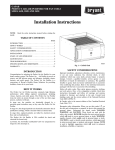
GAPA
PERFECT AIRT PURIFIER
SIZES 1625 AND 2025
Installation, Start--Up, and
Operating Instructions
NOTE: Read the entire instruction manual before starting the
install.
This symbol →indicates a change since the last issue.
TABLE OF CONTENTS
Page
INTRODUCTION . . . . . . . . . . . . . . . . . . . . . . . . . . . . . . . . . . 1
HOW IT WORKS . . . . . . . . . . . . . . . . . . . . . . . . . . . . . . . . . . 1
SAFETY CONSIDERATIONS . . . . . . . . . . . . . . . . . . . . . . . . 1
APPLICATION CONSIDERATIONS . . . . . . . . . . . . . . . . . . 2
INSTALLATION . . . . . . . . . . . . . . . . . . . . . . . . . . . . . . . . . 3--5
START--UP AND OPERATION . . . . . . . . . . . . . . . . . . . . . . . 6
MAINTENANCE . . . . . . . . . . . . . . . . . . . . . . . . . . . . . . . . . . 6
TROUBLESHOOTING . . . . . . . . . . . . . . . . . . . . . . . . . . . . . . 7
SPECIFICATIONS AND DIMENSIONS . . . . . . . . . . . . . . . . 8
WARRANTY . . . . . . . . . . . . . . . . . . . . . . . . . . . . . . . . . . . . . . 9
A06054
INTRODUCTION
Fig. 1 -- GAPA Unit
Congratulations for selecting the Perfect Airt Purifier for your
home comfort system! The Perfect Airt Purifier is proven to
remove and kill airborne germs and allergens, including viruses,
bacteria, and mold spores. The Perfect Airt Purifier is a
cornerstone of Bryant’s Perfect AirtSolutions for providing
healthier, cleaner air in your home.
SAFETY CONSIDERATIONS
Improper installation, adjustment, alteration, service,
maintenance, or use can cause explosion, fire, electrical shock
or other conditions which may cause personal injury or property
damage. Consult a qualified installer, service agency, or your
distributor or branch for information or assistance. The
qualified installer or agency must use factory authorized kits or
accessories when modifying this product. Refer to the
individual instructions packaged with the kits or accessories
when installing.
HOW IT WORKS
The Perfect Airt Purifier provides extremely high filtration
performance while killing captured contaminants, including
viruses, bacteria, and mold spores. The Perfect Airt Purifier
treats the entire air--stream through a state of the art, three--stage
process, exclusive to Bryant.
Follow all safety codes. Wear safety glasses and work gloves.
Have fire extinguisher available. Read these instructions
thoroughly and follow all warning or cautions attached to the
unit. Consult local building codes and National Electrical Code
(NEC) for special requirements.
In stage one, the particles are electrically charged by a
precision--point ionization array as they enter the Perfect Airt
Purifier.
It is important to recognize safety information. This is the
In stage two, the charged particles are electrically attracted to
the air purification cartridge, which is located within an electric
field.
safety--alert symbol
. When you see this symbol on the unit
and in instructions or manuals, be alert to the potential for
personal injury. Understand the signal words DANGER,
WARNING, and CAUTION. These words are used with the
safety--alert symbol. DANGER identifies the most serious
hazards which will result in severe personal injury or death.
WARNING signifies hazards which could result in personal
injury or death. CAUTION is used to identify unsafe practices
which may result in personal injury or product and property
damage. NOTE is used to highlight suggestions which will
result in enhanced installation, reliability, or operation.
In stage three, captured particles are killed by electrical current
flow and ion bombardment.
1
APPLICATION CONSIDERATIONS
Transitions
If the return air duct or furnace openings do not fit the Perfect
Air t Purifier cabinet openings, gradual transitions are
recommended to reduce air turbulence and maximize efficiency.
No more than 20 degrees (about 4 in. per running ft) of
expansion should be used on each side of the transition fitting.
The Perfect Airt Purifier is designed for use in the return air
duct of a forced air heating, cooling, and ventilation system.
Models GAPAAXBB1625 and GAPAAXBB2025 are
specifically designed for use in systems with a forced air gas
furnace.
Turning Vanes
Air Conditioning
If the Perfect Airt Purifier is installed adjacent to a 90 degree
duct elbow, turning vanes should be added inside duct to
improve air distribution across the face of the air purifier.
The Perfect Airt Purifier should be installed in a system so
that all the return air is circulated through the air purifier. It
should be located upstream of both the furnace and the air
conditioning evaporator coil. This will help keep the furnace
and evaporator coil clean and prevent condensation from
forming within the Perfect Airt Purifier.
Electrical Power
The Perfect Airt Purifier should only be powered when airflow
is present. The furnace control EAC terminals provide power
only when the furnace blower is operating. Perfect Air t
Purifier models GAPAAXBB1625 and GAPAAXBB2025 are
designed to be powered from the electronic air cleaner (EAC)
terminals on a furnace electronic control. If EAC terminals are
not available, an alternative airflow sensing mechanism must be
used to ensure the Perfect Airt Purifier is only powered when
airflow is present. Contact local Bryant distributor for
information on approved alternatives.
GAPA
Humidifiers
An evaporative humidifier can be mounted upstream of the
Perfect Airt Purifier. It is best to install atomizing humidifiers
downstream of the air purifier because hard water salt deposits
and water droplets may damage air purifier. If an atomizing
humidifier must be mounted upstream of the Perfect Air t
Purifier, it should be mounted as far upstream as possible (at
least 6 ft recommended), and a standard disposable furnace
filter should be mounted between the humidifier and the air
purifier to trap hard water salt deposits and water droplets.
Door (x1)
Air Purification Cartridge (x1)
Cabinet (x1)
Enhancement Module (x1)
Furnace Adapters (x2)
Safety Screen (x1)
(x1)
(x2)
(x1)
(x2)
Duct Gasket Tape
(1 roll)
(x2)
Installation Components
(in bag attached to power cord)
Installation Manual
Return Duct Adapters:
Long (x2) / Short (x2)
A06064
Fig. 2 -- Perfect Airt Purifier Components
2
INSTALLATION
Step 7—Identify Mounting Location
a. Identify a mounting orientation for the Perfect Airt
Purifier in the return air duct (see Fig. 3).
Step 6—Check Perfect Airt Purifier Components
CAUTION
b. Ensure airflow direction through the Perfect Airt Purifier matches the arrows on the face of the air purifier
cartridge. The Perfect Airt Purifier can be rotated 180
degrees to accommodate the cabinet orientation.
CUT HAZARD
Failure to follow this caution may result in personal injury.
c. The location of the Perfect Airt Purifier should be
readily accessible. Enough room should be provided for
periodic replacement of the air purifier cartridges.
Sheet metal parts may have sharp edges or burrs. Use care
and wear appropriate protective clothing and gloves when
handling parts.
!
b. Carefully remove all items from the box.
WARNING
ELECTRICAL SHOCK AND UNIT DAMAGE
HAZARD
Failure to follow this warning could result in personal
injury or death.
Only a trained, experienced service person should install
the Perfect Airt Purifier. A thorough check of the unit
installation should be completed before unit operation.
Before performing installation, service or maintenance
operations on unit, turn off all power to unit. Tag
disconnect switch with lockout tag.
NOTE:
Mounting on this side
requires the cabinet
to be rotated 180° for
correct air flow.
Airflow
Airflow
Airflow
Upflow Furnace with Side Return
Upflow Furnace with Bottom Mount
Downflow Furnace with Top Mount
Airflow
Horizontal Application
A06067
Fig. 3 -- Perfect Airt Purifier Cabinet Orientation
3
GAPA
!
Step 8—Mount the Cabinet
a. Turn off power to the heating and cooling system.
b. Remove the existing furnace filter and discard.
Excessive system static may result if the Perfect Airt
Purifier is used with other filtration devices.
!
WARNING
c. Remove the air purifier cartridge and enhancement
module from the Perfect Airt Purifier cabinet.
d. Position the cabinet between the furnace and return air
duct (see Fig. 4). A transition duct may be required.
ELECTRICAL SHOCK HAZARD
Failure to follow this warning could result in personal injury
or death.
e. Furnace adapters have been included for installer
convenience. They are designed for top or bottom
mount installations (see Fig. 5).
Before installing or servicing system, always turn off main
power to system. There may be more than 1 disconnect
switch.
f. Return air duct adapters have been included for installer
convenience. They should be used to connect the
upstream side of the air purifier cabinet to the return air
duct (see Fig. 6).
GAPA
g. Install foam tape between the furnace and the air
purifier cabinet.
!
CAUTION
h. Mounting holes are provided for ductwork and furnace
attachment.
UNIT DAMAGE HAZARD
!
Failure to follow this caution may result in equipment
damage.
CAUTION
UNIT DAMAGE HAZARD
Failure to follow this caution may result in unit damage.
Cabinets will support a maximum weight of 400 lbs when
installed beneath a vertical furnace or air--handling unit.
When setting furnace on cabinet, do not drop it into place.
Position the furnace correctly on the cabinet to prevent a
corner from slipping down and damaging the cabinet or its
components.
Mounting holes are provided for duct work and furnace
attachment. The screws on the down--stream side of the
cabinet should be installed so that the screw heads are
inside air purifier cabinet to prevent damage to the air
purifier cartridge.
i. Seal seams with tape or caulking after the Perfect Airt
Purifier cabinet has been secured.
Return Duct
Adapters (x4)
t
Return Duc
Furnace
Adapters (x2)
Furnace
Adapters (x2)
Return Duct
Adapters (x4)
uct
Return D
Top Mount
Bottom Mount
Side Mount
A06029
Fig. 4 -- Mounting Perfect Airt Purifier Cabinet
4
a. Ensure power has been removed from the heating and
cooling system.
Furnace
Adapters
b. Turn the Perfect AirtPurifier power switch off.
c. Connect the power cord to the power supply connector
(see Fig. 7).
d. Route the power cord through nearest cabinet hole and
protect with enclosed cable connector. Zip ties have
been enclosed to secure the power cord to the side of the
power supply.
Airflow
e. Attach the quick connect terminals to the furnace
EAC--1 and EAC--2 spade connections. Attach the
ground ring to furnace chassis ground.
Airflow
A05274
NOTE: The Perfect Airt Purifier is to be powered by 115v/60
Hz.
NOTE: The Perfect Airt Purifier should only be powered when
airflow is present. The furnace control EAC spade connections
provide power only when the furnace blower is operating. If EAC
connections are not available, an alternative airflow sensing
mechanism must be used to ensure the Perfect Airt Purifier is
only powered when airflow is present. Contact a local Bryant
distributor for information on approved alternatives.
Note (optional): Slip return
duct adapters onto flanges
on air return duct side
!
UNIT COMPONENT DAMAGE HAZARD
A05277
Fig. 6 -- Use of Return Duct Adapters
Failure to follow this caution may result in equipment
damage or improper operation.
Step 9—Wiring
!
Black Lead -- Connect to HOT (L1) or EAC--1 when
provided.
White Lead -- Connect to Neutral (L2) or EAC--2 when
provided.
Green/Ground Lead -- Connect to Appliance Ground
(Chassis)
WARNING
ELECTRICAL SHOCK HAZARD
Failure to follow this warning could result in personal injury
or death.
Before installing or servicing system, always turn off main
power to system. There may be more than 1 disconnect
switch.
!
CAUTION
CAUTION
EQUIPMENT DAMAGE HAZARD
Failure to follow this caution may result in equipment
damage or improper operation.
This unit cannot be powered directly from blower motor
leads. Voltages can exceed 190 VAC (120v motors). Do
not wire directly to blower motor. Wiring to blower motor
will damage power supply and void warranty.
5
GAPA
Fig. 5 -- Use of Furnace Adapters
Power Cord
to EAC Terminals
Sample Furnace Circuit Board
HUM
PLT
Power Cord
TEST/TWIN
Use terminals to connect the
power cord wires to the furnace
EAC-1 & 2, & ground terminals
ACRDJ
Power Supply
1 2 3
LHT
OFF
DLY
Y1 DHUM G COM WW1 Y/Y2
24V
Power Supply Connector
Power Supply Connector
ON
OFF
W2
Use cable connector to secure
power cord to cabinet
0.5-AMP024 VAC
R
SEC-1
SEC-2
NEUTRAL-L2
PL3
OD E
EAC-2
PL1
US C
EAC-2 TERMINAL
Use wire ties to secure power cord
to power supply enclosure
LED
FUSE 3-AMP
STAT
1
1
BLW
BHI/LOR
BHT/CLR
BLWR
HI HEAT
IDM
PR-1
PL2
L1
EAC-1
1
1-AMP@115 VAC
SPARE-2
IHI/LOR
HSIR
IDR
LO HEAT
Alternate Power Cord
Pass-Thru Hole
COOL
SPARE-1
HSI
HI LO
GAPA
EAC-1 TERMINAL
A06030
Fig. 7 -- Perfect Airt Purifier Electrical Connections
START--UP AND OPERATION
should use their discretion to select the most appropriate
option based on the initial system static pressure.
Step 1—Checking Air Purifier Operation
!
Step 3—Maximizing Performance
WARNING
a. Maximum air purification performance is obtained
when the furnace blower is set for continuous operation
on the thermostat or Evolutiont Control.
ELECTRICAL SHOCK HAZARD
Failure to follow this warning could result in personal
injury or death.
Before installing or servicing system, always turn off
main power to system. There may be more than one (1)
disconnect switch.
Power Indicator
a. Attach the Perfect Airt Purifier door to the cabinet. A
magnet in the door (see Fig. 9) is used to activate a safety switch in the power supply when the door is installed.
The power supply will not energize the air purifier unless the safety switch is activated.
b. Turn the HVAC system power on and adjust the
thermostat or Evolutiont System Control to activate
the system fan.
c. Turn the Perfect Airt Purifier power switch to on
position.
d. The power indicator light above the Air Purifier power
switch should illuminiate (see Fig. 8).
A06065
Fig. 8 -- Power Indicator
e. Check to ensure the light goes off when the Perfect
Airt Purifier power switch is set to off, when the
blower goes off, or when the HVAC system power is
turned off.
MAINTENANCE
The Perfect Airt Purifier is designed to require no cleaning.
Maintenance is limited to the replacement of the air purification
cartridge. Frequency of air purifier cartridge replacement may
vary depending on ductwork design and local environmental
conditions.
Step 2—Evolutiont Control
a. When the Perfect Airt Purifier is used with an
Evolutiont Control, the Evolutiont Control can be
configured to remind the homeowner when it is time to
change the Perfect Airt Purifier cartridge. This
maintenance reminder can be based on either the
TrueSenset dirty filter algorithm or time. The installer
To replace the air purifier cartridge, complete the following
steps:
6
TROUBLESHOOTING
Step 1—Turn the heating and cooling system off.
WARNING
!
ELECTRICAL SHOCK HAZARD
CAUTION
SAFETY HAZARD
Failure to follow this warning could result in personal
injury or death.
Failure to follow this caution may result in personal
injury or equipment damage.
Before installing or servicing system, always turn off
main power to system. There may be more than one (1)
disconnect switch.
The following instructions are for use by qualified
personnel only.
Step 2—Turn the Perfect Airt Purifier switch to the off
position.
!
Step 3—Remove the Perfect Airt Purifier door.
WARNING
ELECTRICAL SHOCK HAZARD
Step 4—Slide out the old air purifier cartridge and discard.
Failure to follow this warning could result in personal injury
or death.
Step 5—Install the new air purifier cartridge.
The following procedures will expose electrical
components. Disconnect power between checks and then
proceed carefully.
NOTE: Make sure that the arrows on the air purifier cartridge
point toward the furnace. This should be in the same direction as
airflow.
Step 6—Replace the Perfect Airt Purifier door.
The Perfect Airt Purifier is equipped with a power indicator
light located on the door (see Fig. 8). This power indicator light
will illuminate when the Perfect Airt Purifier door is installed,
the power switch is in the on position, AND the furnace blower
is running. If the power indicator light is not illuminated, follow
the troubleshooting steps below.
Step 7—Turn the Perfect Airt Purifier switch to the on
position.
Step 8—Turn on the heating and cooling system.
Step 1—Check that the Perfect Airt Purifier door is installed.
NOTE: A magnet in the door (see Fig. 9) is used to activate a safety
switch in the power supply when the door is installed. The power
supply will not energize the air purifier unless the safety switch is
activated.
Step 2—Check that the Perfect Airt Purifier power switch is in
the on (closed) position.
Door Switch Magnet
Step 3—Confirm that the furnace blower is operating.
NOTE: Power will not be supplied to the Perfect Airt Purifier
from the furnace controls EAC terminals unless the blower is
running.
Step 4—Confirm that power provided from the furnace control
EAC terminals is being conducted through the wiring to the
Perfect Airt Purifier power supply.
Step 5—If all of the above steps are completed and the power
indicator light is still not illuminating, replace the power supply
on the enhancement module. Note that there are no serviceable
parts within the power supply.
A06066
Fig. 9 -- Door Switch Magnet
7
GAPA
!
Specifications and Dimensions
Specifications
Color
Cabinet Material
GAPAAXBB2025
Taupe Metallic
Taupe Metallic
20 Ga. Powder Coated Steel
20 Ga. Powder Coated Steel
115v/60 Hz (from furnace EAC terminals)
115v/60 Hz (from furnace EAC terminals)
1600
2000
Equivalent to MERV 15
Equivalent to MERV 15
GAPBBCAR1625
GAPBBCAR2025
Dimensions
GAPAAXBB1625
GAPAAXBB2025
A
18---3/8
21---7/8
B
15---1/8
18---5/8
C
11---1/8
11---1/8
D
17---1/2
21
E
22--1/8
22--1/8
F
25---1/4
25---1/4
Electrical
Maximum Airflow (CFM)
Efficiency
Replacement Cartridge
GAPA
GAPAAXBB1625
1 3/16"
A
B
D
7/16" (Typical Top & Bottom)*
C
E
F
1 3/16
1 3/16
1 15/16
A06069
Fig. 10 -- Dimensions
8
Bryant Heating & Cooling Systems
FOR SERVICE OR REPAIR, FOLLOW THESE STEPS IN ORDER:
FIRST: Contact the installer. You may find their name on the furnace or in your Homeowner’s Packet. If the installer’s name is not known, call your
builder or home retailer if yours is a new residence.
SECOND: Contact the nearest distributor. (See telephone yellow pages.)
THIRD: Contact:
Bryant Heating and Cooling Systems
Consumer Relations
P.O. Box 4808
Syracuse, New York 13221
Phone: 1-800-428-4326
Model No. ____________________________________________
Unit Serial No. ________________________________________
Date of Installation _____________________________________
Installed by ___________________________________________
Name of Owner _______________________________________
Address of Installation __________________________________
LIMITED WARRANTY
FIVE-YEAR LIMITED WARRANTY –Bryant Heating and Cooling Systems (hereinafter referred to as “Company”) warrants this product to be free from
defects in material and workmanship. If a defect is found within five years from date of original installation of product (whether or not actual use begins
on that date) Company will provide a new or remanufactured part, at Company’s sole option, to replace any defective part, without charge for the part
itself.
This warranty does not include labor or other costs incurred for diagnosing, repairing, removing, installing, shipping, servicing or handling of either
defective parts or replacement parts.
WARRANTY CONDITIONS:
1. Warranties apply only to products in their original installation location.
2. Installation, use, care, and maintenance must be normal and in accordance with instructions contained in the Owner’s Manual and Company’s service
information.
3. Defective parts must be returned to the distributor through a registered servicing dealer for credit.
4. All work shall be performed during normal working hours.
LIMITATIONS OF WARRANTIES – ALL IMPLIED WARRANTIES (INCLUDING IMPLIED WARRANTIES OF MERCHANTABILITY AND FITNESS FOR
A PARTICULAR PURPOSE) ARE HEREBY LIMITED IN DURATION TO THE PERIOD FOR WHICH THE LIMITED WARRANTY IS GIVEN AND
APPLIES. SOME STATES DO NOT ALLOW LIMITATIONS ON HOW LONG AN IMPLIED WARRANTY LASTS, SO THE ABOVE MAY NOT APPLY
TO YOU. THE EXPRESSED WARRANTIES MADE IN THIS WARRANTY ARE EXCLUSIVE AND MAY NOT BE ALTERED, ENLARGED, OR
CHANGED BY ANY DISTRIBUTOR, DEALER, OR OTHER PERSON, WHATSOEVER.
COMPANY WILL NOT BE RESPONSIBLE FOR:
1. Normal maintenance as outlined in the installation and servicing instructions or Owner’s Manual, including filter cleaning and/or replacement and
lubrication.
2. Damage or repairs required as a consequence of faulty installation, misapplication, abuse, improper servicing, unauthorized alteration or improper
operation.
3. Failure to start due to voltage conditions, blown fuses, open circuit breakers, or damages due to the inadequacy or interruption of electrical service.
4. Damage as a result of floods, winds, fires, lightning, accidents, corrosive environments or other conditions beyond the control of Company.
5. Parts not supplied or designated by Company, or damages resulting from their use.
6. Company products installed outside the continental U.S.A., Alaska, Hawaii, and Canada.
7. Electricity or fuel costs, or increases in electricity or fuel costs from any reason whatsoever, including additional or unusual use of supplemental
electric heat.
8. ANY SPECIAL INDIRECT OR CONSEQUENTIAL PROPERTY OR COMMERCIAL DAMAGE OF ANY NATURE WHATSOEVER. Some states do
not allow the exclusion of incidental or consequential damages, so the above limitation may not apply to you.
This Warranty gives you specific legal rights, and you may also have other rights which vary from state to state.
Catalog No. 39004DP309
2/06
9
GAPA
EBryant Heating & Cooling Systems 7310 W. Morris St. Indianapolis, IN 46231
Printed in China
Edition Date: 3/06
Manufacturer reserves the right to discontinue, or change at any time, specifications or designs without notice and without incurring obligations.
10
Catalog No. II GAPA--- 0--- 2
Replaces: II GAPA---0---1