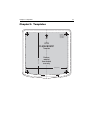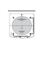
1
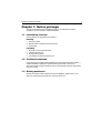
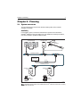
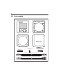
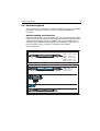
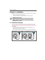
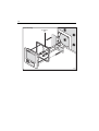
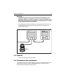
ST70 Instrument
Installation Guide
Document reference: 87079-1
Date: May 2007
ii
Contents
Contents
Chapter 1:Before you begin ............................................................................. 1
1.1Installation overview ............................................................................ 1
1.2Certified installation ............................................................................. 1
1.3Getting assistance .............................................................................. 1
Chapter 2:Planning ............................................................................................ 3
2.1System overviews ............................................................................... 3
2.2Positioning the ST70 instrument ......................................................... 5
2.3Parts supplied ..................................................................................... 6
2.4Parts not supplied ............................................................................... 7
Chapter 3:Installation ....................................................................................... 9
3.1Install the instrument ........................................................................... 9
3.2Install transducers ............................................................................. 14
3.3Final fix .............................................................................................. 15
3.4Commission the instrument ............................................................... 15
Chapter 4:Technical specifications ............................................................ 17
Chapter 5:Templates ....................................................................................... 19
iii
iv
Preface
v
Preface
Contents
Warnings and cautions
WARNING: Product installation and operation
This equipment must be installed, commissioned and operated in
accordance with the Raymarine instructions provided. Failure to
do so could result in personal injury, damage to your boat and/or
poor product performance. Before you install the ST70
instrument, check that individual components are the correct
voltage for your boat’s supply.
WARNING: Electrical safety
Make sure you have switched off the power supply before you start
installing this product.
WARNING: Navigational safety
Although we have designed this product to be accurate and
reliable, many factors can affect its performance. Therefore, it
should serve only as an aid to navigation and should never replace
commonsense and navigational judgement. Always maintain a
permanent watch so you can respond to situations as they
develop.
Electromagnetic Compatibility (EMC) conformance
Raymarine equipment and accessories conform to the appropriate Electromagnetic
Compatibility (EMC) regulations for use in the recreational marine environment.
Correct installation is required to ensure that EMC performance is not compromised.
Always check the installation before going to sea to make sure that it is not affected by
radio transmissions, engine starting or other forms of interference.
To do this:
1. Turn on all transmitting equipment (radar, VHF radio, etc).
2. Check that all electronic systems are unaffected by interference from the transmitting equipment.
EMC installation guidelines
Raymarine equipment and accessories conform to the appropriate Electromagnetic
Compatibility (EMC) regulations. This minimizes electromagnetic interference
between equipment, which could otherwise affect the performance of your system.
Correct installation is required to ensure that EMC performance is not compromised.
For optimum EMC performance, we make the following recommendations:
vi
•
•
•
•
•
Place Raymarine equipment and cables at least 3 ft (1 m) from any equipment that
transmits, or cables that carry, radio signals from VHF radios, cables and antennas. In the case of SSB radios, the distance should be increased to 7 ft. (2 m).
Place Raymarine equipment and cables more than 7 ft (2 m) from the path of a
radar beam. A radar beam can normally be assumed to spread 20 degrees above
and below the radiating element.
Use a power source separate from that used for engine-start. This is important to
prevent erratic behavior and data loss which can occur if the engine-start does not
have a separate battery.
Use Raymarine-specified cables.
Do not cut or extend cables unless doing so is detailed in the installation manual.
Remember
Where constraints on the installation prevent any of the above recommendations:
•
Always allow the maximum separation possible between different items of electrical equipment.
This will provide the best conditions for good EMC performance of the installation.
Suppression ferrites
Raymarine cables may be fitted with suppression ferrites. These are necessary for
correct EMC performance. Any ferrite removed during installation must be replaced
as soon as installation is complete.
Use only ferrites of the correct type, supplied by Raymarine authorized dealers.
Connections to other equipment
If Raymarine equipment is to be connected to other equipment using a cable not
supplied by Raymarine, a Raymarine suppression ferrite MUST always be attached
to the cable near the Raymarine unit.
EMC Servicing and maintenance
•
•
Undue noise and interference may be a symptom of an EMC-related problem.
Please report any EMC-related problem to your nearest Raymarine dealer. We
use such information to improve our quality standards.
To minimize any EMC related problems and ensure the best possible performance form your Raymarine equipment, follow the guidelines given in the installation instructions.
Product documents
The following user documents are available to help you install and operate an ST70
instrument controller:
• ST70 Instrument Installation Guide (this document).
• ST70 Instrument Operating Guide.This is a detailed manual supplied with your
ST70 instrument. It contains important commissioning instructions.
• SeaTalkng Reference Manual. This provides detailed information regarding
SeaTalkng connectivity.
Preface
vii
To the best of our knowledge, the information in the product documents was correct
when they went to press. However, Raymarine cannot accept liability for any
inaccuracies or omissions in product documents.
In addition, our policy of continuous product improvement may change specifications
without notice. Therefore, Raymarine cannot accept liability for any differences
between the product and the accompanying documents.
Product disposal
Waste Electrical and Electronic (WEEE) Directive
The WEEE Directive requires the recycling of waste electrical and electronic
equipment.
Whilst the WEEE Directive does not apply to some of Raymarine's products,
we support its policy and ask you to be aware of how to dispose of this product.
The crossed out wheelie bin symbol, illustrated above, and found on our products
signifies that this product should not be disposed of in general waste or landfill.
Please contact your local dealer, national distributor or Raymarine Technical Services
for information on product disposal.
viii
Chapter 1: Before you begin
Chapter 1: Before you begin
The ST70 instrument must be installed correctly. For a safe and successful
installation, we recommend a certified installation.
1.1 Installation overview
The key steps in the procedure are as follows:
Planning
1. Plan your system.
2. Decide where to locate the ST70 instrument.
3. Check parts.
Installing
1.
2.
3.
4.
Mount and connect the instrument.
Install the transducers.
Fix equipment in place.
Commission the instrument before use.
1.2 Certified installation
Raymarine recommends certified installation by a Raymarine approved installer. A
certified installation qualifies for enhanced warranty benefits. Contact your
Raymarine dealer for further details and refer to the separate warranty card packed
with your product.
1.3 Getting assistance
Should you require further assistance with your installation, please refer to your
dealer or visit the Raymarine web site: www.raymarine.com.
1
2
Chapter 2: Planning
3
Chapter 2: Planning
2.1 System overviews
The ST70 instrument is connected to the boat’s data system, which could be
SeaTalkng or SeaTalk.
SeaTalkng
In a SeaTalkng system, instruments and transducer pods are connected to the
SeaTalkng backbone using spur cables. For more detailed connectivity information,
refer to the SeaTalkng System Installation Guide.
ST70 instruments
Transducer pod
Wind
transducer
SeaTalkng backbone
Power Supply
12V dc
SeaTalkng backbone
Transducer
pod
Transducer
pod
Depth
transducer
Speed
transducer
D10397-1
Note: See page 7 for information about additional SeaTalkng cables and accessories, including
the SeaTalkng backbone kit.
4
SeaTalk
In a SeaTalk system, the ST70 instrument is connected to existing instruments using
a SeaTalkng to SeaTalk adapter cable; wind, speed and depth transducers are
connected directly to instruments.
Wind
transducer
ST70 instrument
ST60+ depth
instrument
SeaTalkng to SeaTalk
adaptor cable
ST60+ speed
instrument
SeaTalk cable
Depth
transducer
ST60+ wind
instrument
SeaTalk
cable
SeaTalk
cable
Speed
transducer
Power Supply
12V dc
D10398-1
Chapter 2: Planning
5
2.2 Positioning the ST70 instrument
ST70 dimensions
Flush
mount
110 mm (4.33 in)
24 mm
(0.95 in)
6.5 mm
(0.25 in)
104 mm (4.1 in)
Surface
mount
90 mm (3.54 in)
•
115 mm (4.53 in)
•
•
CAUTION: Instruments must be placed a safe distance from equipment
that could adversely effect their performance. Refer to the EMC
guidelines on page v.
There must be sufficient space to mount the instrument.
The connection point should be within 400mm of the install location (unless you
are using an extension cable). In a SeaTalkng network, the connection point will be
a T-piece or connector block on the backbone cable, or another ST70 instrument;
on SeaTalk, the connection point will be an existing instrument, or a connector
block on the system.
Any holes cut to mount the instrument must not compromise the vessel’s structure.
24 mm
(0.95 in)
D10400-1
6
2.3 Parts supplied
ST70 instrument parts supplied
ST70 instrument (Part Number E22105)
Mounting bracket (Part Number R28199)
Panel seal (Part Number R28200)
Sun cover (Part Number R28198)
Stud (x 4)
Finger nut (x 4)
SeaTalkng blanking plug
(Part Number A06032)
SeaTalkng 400 mm cable (Part Number A06038)
SeaTalkng to SeaTalk 400 mm cable (Part Number A06047)
D10399-1
Chapter 2: Planning
7
2.4 Parts not supplied
ST70 instruments are connected to a SeaTalk or SeaTalkng data system. To install the
instrument to your system correctly, you may require additional cables and
connectors.
Optional cabling and connectors
Depending on the location of your ST70 instrument, you may require a longer cable to
connect it to the SeaTalkng backbone cable.The backbone cable is supplied as part of
a standard kit. Detailed information on SeaTalkng connectivity is available in the
SeaTalkng System Installation Guide supplied with the SeaTalkng backbone kit. For
further information, talk to you dealer or visit the Raymarine website:
www.raymarine.com.
Spur cable
Part number
A06038 - 1 ft 3 in
A06034 - 3 ft 3 in
A06035 - 9 ft 10 in
A06036 - 16 ft 4 in
A06067 - 65 ft 7 in
Backbone kit
(400 mm)
(1 m)
(3 m)
(5 m)
(20 m)
A25062
Backbone cable 16 ft 4 in (5 m), (x 2)
65 ft 7 in (20 m)
T piece, (x 4)
Backbone terminator, (x 2)
Power cable
D10420-1
8
Chapter 3: Installation
9
Chapter 3: Installation
Read Planning on page 3 of this guide before you install the instrument. It helps you
to:
• Ensure you have all the correct equipment.
• Identify the install location and appropriate network connection point.
WARNING: Electrical safety
Before you make any electrical connections, ensure the power
supply is switched off and you have read the EMC installation
guidelines (see page v). For safety, your boat must be at dockside
before you begin installation.
3.1 Install the instrument
Once you are certain it is safe to proceed, follow the installation procedure below.
1. Fit cable to system connection point and route to ST70 instrument location
For SeaTalkng:
•
•
Label both ends of the SeaTalkng cable, and attach it to the backbone or an
existing ST70 instrument on your system.
Route the cable to the location in which you plan to mount the ST70 instrument.
ng
SeaTalkng backbone SeaTalk T piece
ST70 instrument
SeaTalkng spur
SeaTalkng T piece
SeaTalkng backbone
ST70 instrument
ST70 instrument
SeaTalkng spur
SeaTalkng spur
D10419-1
10
For SeaTalk:
•
•
Label both ends of the SeaTalkng-to-SeaTalk adaptor cable, and attach it to an
existing instrument or connect it to a connector block on the system.
Route the cable to the location in which you plan to mount the ST70 instrument.
SeaTalk cable
ST70 instrument
SeaTalk cable
ST70 instrument
ST60+ instrument
SeaTalkng to SeaTalk cable
ST60+ instrument
SeaTalkng to
SeaTalk cable
SeaTalk 3 way block
SeaTalk cable
D10421-1
Note: Check that the cable reaches the required location. If you wish to place the ST70 instru-
ment further than 400mm from the connection point you will need to purchase an appropriate
SeaTalkng or SeaTalkng-to-SeaTalk cable. See page 7.
2. Cut mounting holes
•
•
Use the appropriate flush- or surface-mount template to cut the mounting slot for
the instrument and to drill holes for the fixing screws. See the back of this book for
templates.
Clean and de-burr the mounting surface.
Chapter 3: Installation
11
3. Fit gaskets and brackets
Note: Stick the self-adhesive side of the gasket to the instrument, NOT to the mounting location.
Surface mounting
self adhesive
side
D10404-1
12
Flush mounting
self adhesive
side
D10403-1
Chapter 3: Installation
13
4. Attach connection cable to the instrument
2. Ensure cable end connector is
correctly oriented, then fully insert
1. Rotate collar to UNLOCKED position
3. Rotate collar clockwise
(2 clicks) until it snaps
into the LOCKED position
D10422-1
14
3.2 Install transducers
Transducers and pods are available for wind, depth and speed. For detailed
installation instructions refer to documentation supplied with pods.
SeaTalkng
•
•
Fit transducers to pods. Pod terminals are color-coded, so ensure that each wire
is connected to the correspondingly-colored connector.
Fit each pod to the SeaTalkng backbone using the 400mm SeaTalkng spur cable
supplied with each pod. Pods must be located no further than 400mm from their
corresponding connection points on the backbone.
SeaTalkng backbone
SeaTalkng T piece
Speed pod
Speed
transducer
15 metre cable
SeaTalkng spur 400mm cable
D10417-1
Chapter 3: Installation
15
SeaTalk
CAUTION: Using the wrong type of pod could cause damage to your
equipment. Before you connect a transducer to a pod, ensure that you are
using the correct type of pod (speed pod for a speed transducer or depth
pod for a depth transducer, for example).
•
Fit the appropriate transducer directly to its corresponding instrument as shown.
Pod connectors are color-coded. Ensure that each wire is connected to its
corresponding connector.
ST60+ speed instrument
ST70 instrument
Speed
transducer
D10418-1
3.3 Final fix
•
Ensure the controller is mounted securely.
3.4 Commission the instrument
The instrument must be commissioned before you use. For new systems this involves
calibrating the instrument, which is a safety-critical action. Refer to the ST70
Instrument Reference Manual for instructions.
16
Chapter 4: Technical specifications
17
Chapter 4: Technical specifications
Supply voltage
12 V dc (nominal)
16 V dc (maximum)
9 V dc (minimum)
Current
Nominal: dependent upon screen brightness
Maximum: not more than 220 mA
Physical dimensions
(excluding studs)
4.33(W) x 4.53 (H) x 1.28 (D)
110 mm x 115 mm x 32.5 mm
Weight
250 g (approx.)
Connections
Two SeaTalkng
Operating temperature
-20ºC to +70ºC
Illumination
Sliding scale
Compliances
RoHS; EMC EN60945 Revision 4
Buzzer
Monotone buzzer
Load Equivalency Number
(LEN)
5
Note: System components have a Load Equivalency Number (LEN), which contributes to the
overall system load. Your system has a maximum load capacity, which must not be exceeded.
For more detailed information on SeaTalkng system capacity refer to the SeaTalkng Reference
Manual.
18
Chapter 5: Templates
19
Chapter 5: Templates
Drill hole,
9/32 in (7 mm)
diameter in
4 positions
UP
ST70
FLUSH MOUNT
4.1 in (104 mm)
Template
Remove
material
from shaded
area only
3.9 in (99 mm)
Instrument edge
Sun cover edge
D10405-1
20
UP
SURFACE MOUNT
Template
Drill hole,
3/16 in
(5 mm)
diameter in
2 positions
1.53 in (38.89 mm)
Cut hole
3.54 in (90 mm)
diameter
Remove material
from shaded
area only
1.53 in (38.89 mm)
Instrument edge
1.53 in (38.89 mm)
ST70
1.53 in (38.89 mm)
Sun cover edge
D10406-1