1
Vixel Module Ref Guide
Revision Notice
This is the second release of this manual. A complete revision history is provided at the end of the manual.
Abstract
The Softek SANView Vixel Module Reference Guide (ML-144957-002) describes features and functionality of Vixel
devices, Softek SANView windows and dialog boxes used for Vixel devices, and Vixel-specific parameters.
For Further Information
If you wish to obtain further information about the Fujitsu Software Technology Corporation product discussed
in this publication, contact your Fujitsu Software Technology Corporation marketing representative, or write to
Fujitsu Software Technology Corporation, Marketing Communications, Mail Stop 323, P.O. Box 3470, Sunnyvale,
CA 94088-3470.
Ordering Additional Publications
If you wish to order additional copies of this publication or publications related to the products described in
this manual, call (800) 438-5715. Customers outside the United States, contact your local Fujitsu Software
Technology Corporation marketing representative.
Restriction On Use
The information contained in this manual is the licensed property of Fujitsu Software Technology Corporation.
Use of the information contained herein is restricted pursuant to the terms and conditions of a license agreement.
Fujitsu Softek and Softek SANView are trademarks of Fujitsu Software Technology Corporation.
Vixel and SAN InSite Professional are trademarks of Vixel Corporation.
Microsoft and Windows are registered trademarks and Windows NT is a trademark of Microsoft Corporation.
All other trademarks and product names are the property of their respective owners.
© 2001 Fujitsu Software Technology Corporation.
All rights reserved. Printed in U.S.A.
All specifications are subject to change without notice.
iv
LICENSED MATERIAL - PROPERTY OF FUJITSU SOFTWARE TECHNOLOGY CORPORATION
Contents
Preface
Chapters
1
Introduction. . . . . . . . . . . . . . . . . . . . . . . . . . . . . . . . . . . . . . . . . . . . . . . . . . . . . . . . . . . . . . . . . . . . . . . . 1
What is Softek SANView? . . . . . . . . . . . . . . . . . . . . . . . . . . . . . . . . . . . . . . . . . . . . . . . . . . . . . . . . . . . . 3
2
Historical Traffic Monitor Window . . . . . . . . . . . . . . . . . . . . . . . . . . . . . . . . . . . . . . . . . . . . . . . . . . . 5
The Historical Traffic Monitor Window . . . . . . . . . . . . . . . . . . . . . . . . . . . . . . . . . . . . . . . . . . . . . . . . 7
3
Firmware Image Configuration Dialog Box . . . . . . . . . . . . . . . . . . . . . . . . . . . . . . . . . . . . . . . . . . . 11
The Firmware Image Configuration Dialog Box . . . . . . . . . . . . . . . . . . . . . . . . . . . . . . . . . . . . . . . . 13
4
Schedule Tasks Option . . . . . . . . . . . . . . . . . . . . . . . . . . . . . . . . . . . . . . . . . . . . . . . . . . . . . . . . . . . . . 15
The Zone Scheduler Dialog Box . . . . . . . . . . . . . . . . . . . . . . . . . . . . . . . . . . . . . . . . . . . . . . . . . . . . . . 17
5
Trap Configuration Dialog Box . . . . . . . . . . . . . . . . . . . . . . . . . . . . . . . . . . . . . . . . . . . . . . . . . . . . . . 19
The Trap Configuration Dialog Box . . . . . . . . . . . . . . . . . . . . . . . . . . . . . . . . . . . . . . . . . . . . . . . . . . 21
6
Manage Licenses Dialog Box . . . . . . . . . . . . . . . . . . . . . . . . . . . . . . . . . . . . . . . . . . . . . . . . . . . . . . . . 25
The Manage Licenses Dialog Box . . . . . . . . . . . . . . . . . . . . . . . . . . . . . . . . . . . . . . . . . . . . . . . . . . . . 27
7
Switch Window. . . . . . . . . . . . . . . . . . . . . . . . . . . . . . . . . . . . . . . . . . . . . . . . . . . . . . . . . . . . . . . . . . . .
Overview . . . . . . . . . . . . . . . . . . . . . . . . . . . . . . . . . . . . . . . . . . . . . . . . . . . . . . . . . . . . . . . . . . . . . . . . .
Title Bar, LED Row, and Icons . . . . . . . . . . . . . . . . . . . . . . . . . . . . . . . . . . . . . . . . . . . . . . . . . . . . . . .
File Menu . . . . . . . . . . . . . . . . . . . . . . . . . . . . . . . . . . . . . . . . . . . . . . . . . . . . . . . . . . . . . . . . . . . . . . . . .
View Menu . . . . . . . . . . . . . . . . . . . . . . . . . . . . . . . . . . . . . . . . . . . . . . . . . . . . . . . . . . . . . . . . . . . . . . .
Device Events . . . . . . . . . . . . . . . . . . . . . . . . . . . . . . . . . . . . . . . . . . . . . . . . . . . . . . . . . . . . . . . .
Port Frame Statistics . . . . . . . . . . . . . . . . . . . . . . . . . . . . . . . . . . . . . . . . . . . . . . . . . . . . . . . . . .
Port Link Statistics . . . . . . . . . . . . . . . . . . . . . . . . . . . . . . . . . . . . . . . . . . . . . . . . . . . . . . . . . . . .
RIP Table . . . . . . . . . . . . . . . . . . . . . . . . . . . . . . . . . . . . . . . . . . . . . . . . . . . . . . . . . . . . . . . . . . . .
FSPF Table . . . . . . . . . . . . . . . . . . . . . . . . . . . . . . . . . . . . . . . . . . . . . . . . . . . . . . . . . . . . . . . . . . .
SNS Table . . . . . . . . . . . . . . . . . . . . . . . . . . . . . . . . . . . . . . . . . . . . . . . . . . . . . . . . . . . . . . . . . . .
Historical Traffic Monitor . . . . . . . . . . . . . . . . . . . . . . . . . . . . . . . . . . . . . . . . . . . . . . . . . . . . . .
Enclosure State . . . . . . . . . . . . . . . . . . . . . . . . . . . . . . . . . . . . . . . . . . . . . . . . . . . . . . . . . . . . . . .
Options Menu . . . . . . . . . . . . . . . . . . . . . . . . . . . . . . . . . . . . . . . . . . . . . . . . . . . . . . . . . . . . . . . . . . . . .
Tools Menu . . . . . . . . . . . . . . . . . . . . . . . . . . . . . . . . . . . . . . . . . . . . . . . . . . . . . . . . . . . . . . . . . . . . . . .
29
31
32
33
34
35
36
37
44
46
48
50
51
52
53
v
Help Menu . . . . . . . . . . . . . . . . . . . . . . . . . . . . . . . . . . . . . . . . . . . . . . . . . . . . . . . . . . . . . . . . . . . . . . . . 54
Interpreting the FC4 Type Value . . . . . . . . . . . . . . . . . . . . . . . . . . . . . . . . . . . . . . . . . . . . . . . . . . . . . . 55
8
Switch Port Window . . . . . . . . . . . . . . . . . . . . . . . . . . . . . . . . . . . . . . . . . . . . . . . . . . . . . . . . . . . . . . . 57
Port Window . . . . . . . . . . . . . . . . . . . . . . . . . . . . . . . . . . . . . . . . . . . . . . . . . . . . . . . . . . . . . . . . . . . . . . 59
9
Configure the Switch Dialog Box . . . . . . . . . . . . . . . . . . . . . . . . . . . . . . . . . . . . . . . . . . . . . . . . . . . . 63
Overview . . . . . . . . . . . . . . . . . . . . . . . . . . . . . . . . . . . . . . . . . . . . . . . . . . . . . . . . . . . . . . . . . . . . . . . . . 65
File Menu . . . . . . . . . . . . . . . . . . . . . . . . . . . . . . . . . . . . . . . . . . . . . . . . . . . . . . . . . . . . . . . . . . . . . . . . . 67
System Tab . . . . . . . . . . . . . . . . . . . . . . . . . . . . . . . . . . . . . . . . . . . . . . . . . . . . . . . . . . . . . . . . . . . . . . . . 68
Time Settings Tab . . . . . . . . . . . . . . . . . . . . . . . . . . . . . . . . . . . . . . . . . . . . . . . . . . . . . . . . . . . . . . . . . . 72
Ports Tab . . . . . . . . . . . . . . . . . . . . . . . . . . . . . . . . . . . . . . . . . . . . . . . . . . . . . . . . . . . . . . . . . . . . . . . . . . 73
Stealth-2/Stealth Tab . . . . . . . . . . . . . . . . . . . . . . . . . . . . . . . . . . . . . . . . . . . . . . . . . . . . . . . . . . . . . . . 77
Stealth-3 Tab . . . . . . . . . . . . . . . . . . . . . . . . . . . . . . . . . . . . . . . . . . . . . . . . . . . . . . . . . . . . . . . . . . . . . . . 81
Logging Tab . . . . . . . . . . . . . . . . . . . . . . . . . . . . . . . . . . . . . . . . . . . . . . . . . . . . . . . . . . . . . . . . . . . . . . . 85
Zoning Tab . . . . . . . . . . . . . . . . . . . . . . . . . . . . . . . . . . . . . . . . . . . . . . . . . . . . . . . . . . . . . . . . . . . . . . . . 86
Version Info Tab . . . . . . . . . . . . . . . . . . . . . . . . . . . . . . . . . . . . . . . . . . . . . . . . . . . . . . . . . . . . . . . . . . . 88
Device Info Tab . . . . . . . . . . . . . . . . . . . . . . . . . . . . . . . . . . . . . . . . . . . . . . . . . . . . . . . . . . . . . . . . . . . . 89
Sensor Info Tab . . . . . . . . . . . . . . . . . . . . . . . . . . . . . . . . . . . . . . . . . . . . . . . . . . . . . . . . . . . . . . . . . . . . 90
Options Tab . . . . . . . . . . . . . . . . . . . . . . . . . . . . . . . . . . . . . . . . . . . . . . . . . . . . . . . . . . . . . . . . . . . . . . . 91
10 Hub Window . . . . . . . . . . . . . . . . . . . . . . . . . . . . . . . . . . . . . . . . . . . . . . . . . . . . . . . . . . . . . . . . . . . . . . 93
Overview . . . . . . . . . . . . . . . . . . . . . . . . . . . . . . . . . . . . . . . . . . . . . . . . . . . . . . . . . . . . . . . . . . . . . . . . . 95
Title Bar, LED Row, and Icons . . . . . . . . . . . . . . . . . . . . . . . . . . . . . . . . . . . . . . . . . . . . . . . . . . . . . . . . 96
File Menu . . . . . . . . . . . . . . . . . . . . . . . . . . . . . . . . . . . . . . . . . . . . . . . . . . . . . . . . . . . . . . . . . . . . . . . . . 98
View Menu . . . . . . . . . . . . . . . . . . . . . . . . . . . . . . . . . . . . . . . . . . . . . . . . . . . . . . . . . . . . . . . . . . . . . . . . 99
Management Agent . . . . . . . . . . . . . . . . . . . . . . . . . . . . . . . . . . . . . . . . . . . . . . . . . . . . . . . . . . . 99
Device Events . . . . . . . . . . . . . . . . . . . . . . . . . . . . . . . . . . . . . . . . . . . . . . . . . . . . . . . . . . . . . . . 100
Historical Traffic Monitor . . . . . . . . . . . . . . . . . . . . . . . . . . . . . . . . . . . . . . . . . . . . . . . . . . . . . 101
Enclosure State . . . . . . . . . . . . . . . . . . . . . . . . . . . . . . . . . . . . . . . . . . . . . . . . . . . . . . . . . . . . . . 102
Options Menu . . . . . . . . . . . . . . . . . . . . . . . . . . . . . . . . . . . . . . . . . . . . . . . . . . . . . . . . . . . . . . . . . . . . 102
Tools Menu . . . . . . . . . . . . . . . . . . . . . . . . . . . . . . . . . . . . . . . . . . . . . . . . . . . . . . . . . . . . . . . . . . . . . . . 103
Help Menu . . . . . . . . . . . . . . . . . . . . . . . . . . . . . . . . . . . . . . . . . . . . . . . . . . . . . . . . . . . . . . . . . . . . . . . 104
11 Port Window . . . . . . . . . . . . . . . . . . . . . . . . . . . . . . . . . . . . . . . . . . . . . . . . . . . . . . . . . . . . . . . . . . . . . 105
Hub Port Window . . . . . . . . . . . . . . . . . . . . . . . . . . . . . . . . . . . . . . . . . . . . . . . . . . . . . . . . . . . . . . . . . 107
12 Configure the Hub Dialog Box . . . . . . . . . . . . . . . . . . . . . . . . . . . . . . . . . . . . . . . . . . . . . . . . . . . . . 111
Overview . . . . . . . . . . . . . . . . . . . . . . . . . . . . . . . . . . . . . . . . . . . . . . . . . . . . . . . . . . . . . . . . . . . . . . . . 113
File Menu . . . . . . . . . . . . . . . . . . . . . . . . . . . . . . . . . . . . . . . . . . . . . . . . . . . . . . . . . . . . . . . . . . . . . . . . 114
Help Menu . . . . . . . . . . . . . . . . . . . . . . . . . . . . . . . . . . . . . . . . . . . . . . . . . . . . . . . . . . . . . . . . . . . . . . . 115
Zoning Tab . . . . . . . . . . . . . . . . . . . . . . . . . . . . . . . . . . . . . . . . . . . . . . . . . . . . . . . . . . . . . . . . . . . . . . . 116
Policies Tab . . . . . . . . . . . . . . . . . . . . . . . . . . . . . . . . . . . . . . . . . . . . . . . . . . . . . . . . . . . . . . . . . . . . . . . 117
vi
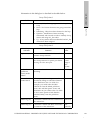
13 Hub Diagnostics Dialog Box . . . . . . . . . . . . . . . . . . . . . . . . . . . . . . . . . . . . . . . . . . . . . . . . . . . . . . .
Overview . . . . . . . . . . . . . . . . . . . . . . . . . . . . . . . . . . . . . . . . . . . . . . . . . . . . . . . . . . . . . . . . . . . . . . . .
Sweep Tab . . . . . . . . . . . . . . . . . . . . . . . . . . . . . . . . . . . . . . . . . . . . . . . . . . . . . . . . . . . . . . . . . . . . . . .
Loop Tab . . . . . . . . . . . . . . . . . . . . . . . . . . . . . . . . . . . . . . . . . . . . . . . . . . . . . . . . . . . . . . . . . . . . . . . .
Port Tab . . . . . . . . . . . . . . . . . . . . . . . . . . . . . . . . . . . . . . . . . . . . . . . . . . . . . . . . . . . . . . . . . . . . . . . . .
119
121
122
126
128
Glossary . . . . . . . . . . . . . . . . . . . . . . . . . . . . . . . . . . . . . . . . . . . . . . . . . . . . . . . . . . . . . . . . . . . . . . . . . . . . 131
Index . . . . . . . . . . . . . . . . . . . . . . . . . . . . . . . . . . . . . . . . . . . . . . . . . . . . . . . . . . . . . . . . . . . . . . . . . . . . . . . 135
Revision History . . . . . . . . . . . . . . . . . . . . . . . . . . . . . . . . . . . . . . . . . . . . . . . . . . . . . . . . . . . . . . . . . . . . . 137
Figures
Historical Traffic Monitor window for a Vixel 7200. . . . . . . . . . . . . . . . . . . . . . . . . . . . . . . . . . . . . . . . . . 7
Firmware Image Configuration Dialog Box . . . . . . . . . . . . . . . . . . . . . . . . . . . . . . . . . . . . . . . . . . . . . . . 13
Zone Scheduler View Dialog Box . . . . . . . . . . . . . . . . . . . . . . . . . . . . . . . . . . . . . . . . . . . . . . . . . . . . . . . . 17
Trap Configuration Dialog Box . . . . . . . . . . . . . . . . . . . . . . . . . . . . . . . . . . . . . . . . . . . . . . . . . . . . . . . . . 22
Manage Licenses Dialog Box . . . . . . . . . . . . . . . . . . . . . . . . . . . . . . . . . . . . . . . . . . . . . . . . . . . . . . . . . . . . 27
Switch Window for a Vixel 7200 Fibre Channel Switch . . . . . . . . . . . . . . . . . . . . . . . . . . . . . . . . . . . . . 31
Switch window for a Vixel 7100, with explanatory call-outs for title bar and LED row . . . . . . . . . 32
File Menu of the Switch Window . . . . . . . . . . . . . . . . . . . . . . . . . . . . . . . . . . . . . . . . . . . . . . . . . . . . . . . . 33
View menu (Switch Window), for a Vixel 7100 running V. 3.0 firmware
(FSPF Routing table used) . . . . . . . . . . . . . . . . . . . . . . . . . . . . . . . . . . . . . . . . . . . . . . . . . . . . . . . . . . . . . . 34
Device Events Window . . . . . . . . . . . . . . . . . . . . . . . . . . . . . . . . . . . . . . . . . . . . . . . . . . . . . . . . . . . . . . . . 35
Port Frame Statistics Window . . . . . . . . . . . . . . . . . . . . . . . . . . . . . . . . . . . . . . . . . . . . . . . . . . . . . . . . . . . 36
Port Link Statistics Window . . . . . . . . . . . . . . . . . . . . . . . . . . . . . . . . . . . . . . . . . . . . . . . . . . . . . . . . . . . . 38
RIP Table and Statistics Window . . . . . . . . . . . . . . . . . . . . . . . . . . . . . . . . . . . . . . . . . . . . . . . . . . . . . . . . 44
FSPF Routing Table Window . . . . . . . . . . . . . . . . . . . . . . . . . . . . . . . . . . . . . . . . . . . . . . . . . . . . . . . . . . . 46
SNS Table Window . . . . . . . . . . . . . . . . . . . . . . . . . . . . . . . . . . . . . . . . . . . . . . . . . . . . . . . . . . . . . . . . . . . . 48
Historical Traffic Monitor Window . . . . . . . . . . . . . . . . . . . . . . . . . . . . . . . . . . . . . . . . . . . . . . . . . . . . . . 50
Enclosure State Window . . . . . . . . . . . . . . . . . . . . . . . . . . . . . . . . . . . . . . . . . . . . . . . . . . . . . . . . . . . . . . . 51
Options menu for a Vixel 7100 Switch window . . . . . . . . . . . . . . . . . . . . . . . . . . . . . . . . . . . . . . . . . . . . 52
Tools menu for a Vixel 9100 Switch window . . . . . . . . . . . . . . . . . . . . . . . . . . . . . . . . . . . . . . . . . . . . . . 53
Configure Switch Dialog Box . . . . . . . . . . . . . . . . . . . . . . . . . . . . . . . . . . . . . . . . . . . . . . . . . . . . . . . . . . . 54
Port windows for an SFP (on a Vixel 9200 Fibre Channel Switch) and a GBIC
(on a Vixel 7200 Switch) . . . . . . . . . . . . . . . . . . . . . . . . . . . . . . . . . . . . . . . . . . . . . . . . . . . . . . . . . . . . . . . . 59
Port window for an FC SW Laser Serial ID GBIC, before and after clicking the Type button . . . . . 62
Configure Switch Dialog Box . . . . . . . . . . . . . . . . . . . . . . . . . . . . . . . . . . . . . . . . . . . . . . . . . . . . . . . . . . . 65
File Menu for the Configure Switch Dialog Box . . . . . . . . . . . . . . . . . . . . . . . . . . . . . . . . . . . . . . . . . . . 67
System Tab, Configure Switch Dialog Box (shown for a Vixel 7100) . . . . . . . . . . . . . . . . . . . . . . . . . . 68
Time Settings Tab, Configure Switch Dialog Box . . . . . . . . . . . . . . . . . . . . . . . . . . . . . . . . . . . . . . . . . . 72
Ports Tab, Configure Switch Dialog Box . . . . . . . . . . . . . . . . . . . . . . . . . . . . . . . . . . . . . . . . . . . . . . . . . . 73
Stealth-2 Tab, Configure Switch Dialog Box . . . . . . . . . . . . . . . . . . . . . . . . . . . . . . . . . . . . . . . . . . . . . . . 77
Stealth Configuration Table Window . . . . . . . . . . . . . . . . . . . . . . . . . . . . . . . . . . . . . . . . . . . . . . . . . . . . 80
Stealth-3 Tab, Configure Switch Dialog Box . . . . . . . . . . . . . . . . . . . . . . . . . . . . . . . . . . . . . . . . . . . . . . . 81
Logging Tab, Configure Switch Dialog Box . . . . . . . . . . . . . . . . . . . . . . . . . . . . . . . . . . . . . . . . . . . . . . . 85
vii
Zoning Tab, Configure Switch Dialog Box (for a switch that uses WWN-based zoning) . . . . . . . . . 86
Zoning Tab, Configure Switch Dialog Box (for a switch that uses port-based zoning) . . . . . . . . . . . 87
Zone Configuration Window . . . . . . . . . . . . . . . . . . . . . . . . . . . . . . . . . . . . . . . . . . . . . . . . . . . . . . . . . . . 87
Version Info Tab, Configure Switch Dialog Box . . . . . . . . . . . . . . . . . . . . . . . . . . . . . . . . . . . . . . . . . . . . 88
Device Info Tab, Configure Switch Dialog Box . . . . . . . . . . . . . . . . . . . . . . . . . . . . . . . . . . . . . . . . . . . . 89
Sensor Info Tab, Configure Switch Dialog Box (shown for Vixel 8100) . . . . . . . . . . . . . . . . . . . . . . . . 90
Options Tab, Configure Switch Dialog Box . . . . . . . . . . . . . . . . . . . . . . . . . . . . . . . . . . . . . . . . . . . . . . . 91
Hub Window . . . . . . . . . . . . . . . . . . . . . . . . . . . . . . . . . . . . . . . . . . . . . . . . . . . . . . . . . . . . . . . . . . . . . . . . . 95
Hub window for a Vixel 2100, with explanatory call-outs for title bar and LED row . . . . . . . . . . . . 96
File Menu of Hub Window . . . . . . . . . . . . . . . . . . . . . . . . . . . . . . . . . . . . . . . . . . . . . . . . . . . . . . . . . . . . . 98
Module Icons for SFPs and GBICs . . . . . . . . . . . . . . . . . . . . . . . . . . . . . . . . . . . . . . . . . . . . . . . . . . . . . . . 98
View Menu of Hub Window . . . . . . . . . . . . . . . . . . . . . . . . . . . . . . . . . . . . . . . . . . . . . . . . . . . . . . . . . . . . 99
Vixel Management Agent Dialog Box . . . . . . . . . . . . . . . . . . . . . . . . . . . . . . . . . . . . . . . . . . . . . . . . . . . . 99
Device Events window for a Vixel 2100 Managed Hub with Zoning . . . . . . . . . . . . . . . . . . . . . . . . . 100
Historical Traffic Monitor Window . . . . . . . . . . . . . . . . . . . . . . . . . . . . . . . . . . . . . . . . . . . . . . . . . . . . . 101
Enclosure State Window . . . . . . . . . . . . . . . . . . . . . . . . . . . . . . . . . . . . . . . . . . . . . . . . . . . . . . . . . . . . . . 102
Options Menu of Hub Window (with port gauges shown) . . . . . . . . . . . . . . . . . . . . . . . . . . . . . . . . . 102
Tools Menu of Hub Window . . . . . . . . . . . . . . . . . . . . . . . . . . . . . . . . . . . . . . . . . . . . . . . . . . . . . . . . . . . 103
Diagnostics Dialog Box . . . . . . . . . . . . . . . . . . . . . . . . . . . . . . . . . . . . . . . . . . . . . . . . . . . . . . . . . . . . . . . . 103
Configure Hub Dialog Box . . . . . . . . . . . . . . . . . . . . . . . . . . . . . . . . . . . . . . . . . . . . . . . . . . . . . . . . . . . . 104
Port window for an FC SW Laser GBIC on a Vixel 2100 . . . . . . . . . . . . . . . . . . . . . . . . . . . . . . . . . . . . 107
Port window for an IntraCopper Serial ID GBIC, before and after clicking the Type button . . . . 110
Configure Hub Dialog Box . . . . . . . . . . . . . . . . . . . . . . . . . . . . . . . . . . . . . . . . . . . . . . . . . . . . . . . . . . . . 114
File Menu for the Configure Hub Dialog Box . . . . . . . . . . . . . . . . . . . . . . . . . . . . . . . . . . . . . . . . . . . . 114
Zoning Tab . . . . . . . . . . . . . . . . . . . . . . . . . . . . . . . . . . . . . . . . . . . . . . . . . . . . . . . . . . . . . . . . . . . . . . . . . . 116
Policies Tab . . . . . . . . . . . . . . . . . . . . . . . . . . . . . . . . . . . . . . . . . . . . . . . . . . . . . . . . . . . . . . . . . . . . . . . . . 117
Sweep Tab . . . . . . . . . . . . . . . . . . . . . . . . . . . . . . . . . . . . . . . . . . . . . . . . . . . . . . . . . . . . . . . . . . . . . . . . . . 122
Loop Tab . . . . . . . . . . . . . . . . . . . . . . . . . . . . . . . . . . . . . . . . . . . . . . . . . . . . . . . . . . . . . . . . . . . . . . . . . . . . 126
Port Tab . . . . . . . . . . . . . . . . . . . . . . . . . . . . . . . . . . . . . . . . . . . . . . . . . . . . . . . . . . . . . . . . . . . . . . . . . . . . 128
Tables
Softek SANView Notations . . . . . . . . . . . . . . . . . . . . . . . . . . . . . . . . . . . . . . . . . . . . . . . . . . . . . . . . . . . . viii
Firmware Image Configuration Dialog Box Selections . . . . . . . . . . . . . . . . . . . . . . . . . . . . . . . . . . . . . . 14
Selections Under Edit Selected Item . . . . . . . . . . . . . . . . . . . . . . . . . . . . . . . . . . . . . . . . . . . . . . . . . . . . . . 18
Trap List . . . . . . . . . . . . . . . . . . . . . . . . . . . . . . . . . . . . . . . . . . . . . . . . . . . . . . . . . . . . . . . . . . . . . . . . . . . . . 22
Selections Under Edit Select Item . . . . . . . . . . . . . . . . . . . . . . . . . . . . . . . . . . . . . . . . . . . . . . . . . . . . . . . . 23
Device Feature List . . . . . . . . . . . . . . . . . . . . . . . . . . . . . . . . . . . . . . . . . . . . . . . . . . . . . . . . . . . . . . . . . . . . 27
LED Color Legend of the Switch Window . . . . . . . . . . . . . . . . . . . . . . . . . . . . . . . . . . . . . . . . . . . . . . . . 32
Port LED of the Switch Window . . . . . . . . . . . . . . . . . . . . . . . . . . . . . . . . . . . . . . . . . . . . . . . . . . . . . . . . . 32
Module Icons for SFPs and GBICs . . . . . . . . . . . . . . . . . . . . . . . . . . . . . . . . . . . . . . . . . . . . . . . . . . . . . . . 33
Port Frame Statistics Columns . . . . . . . . . . . . . . . . . . . . . . . . . . . . . . . . . . . . . . . . . . . . . . . . . . . . . . . . . . 36
Port Link Statistics Columns . . . . . . . . . . . . . . . . . . . . . . . . . . . . . . . . . . . . . . . . . . . . . . . . . . . . . . . . . . . . 39
RIP Table Columns . . . . . . . . . . . . . . . . . . . . . . . . . . . . . . . . . . . . . . . . . . . . . . . . . . . . . . . . . . . . . . . . . . . . 45
RIP Statistics . . . . . . . . . . . . . . . . . . . . . . . . . . . . . . . . . . . . . . . . . . . . . . . . . . . . . . . . . . . . . . . . . . . . . . . . . . 46
FSPF Table Columns . . . . . . . . . . . . . . . . . . . . . . . . . . . . . . . . . . . . . . . . . . . . . . . . . . . . . . . . . . . . . . . . . . . 47
SNS Table Columns . . . . . . . . . . . . . . . . . . . . . . . . . . . . . . . . . . . . . . . . . . . . . . . . . . . . . . . . . . . . . . . . . . . 49
FC4 Type Values . . . . . . . . . . . . . . . . . . . . . . . . . . . . . . . . . . . . . . . . . . . . . . . . . . . . . . . . . . . . . . . . . . . . . . 55
viii
Port Control Values . . . . . . . . . . . . . . . . . . . . . . . . . . . . . . . . . . . . . . . . . . . . . . . . . . . . . . . . . . . . . . . . . . . 60
GBIC Values . . . . . . . . . . . . . . . . . . . . . . . . . . . . . . . . . . . . . . . . . . . . . . . . . . . . . . . . . . . . . . . . . . . . . . . . . . 60
Configure Switch Dialog Box Buttons . . . . . . . . . . . . . . . . . . . . . . . . . . . . . . . . . . . . . . . . . . . . . . . . . . . . 66
System Tab Options . . . . . . . . . . . . . . . . . . . . . . . . . . . . . . . . . . . . . . . . . . . . . . . . . . . . . . . . . . . . . . . . . . . 69
Ports Tab Options . . . . . . . . . . . . . . . . . . . . . . . . . . . . . . . . . . . . . . . . . . . . . . . . . . . . . . . . . . . . . . . . . . . . . 74
Stealth-2 Tab Options . . . . . . . . . . . . . . . . . . . . . . . . . . . . . . . . . . . . . . . . . . . . . . . . . . . . . . . . . . . . . . . . . . 78
Stealth-3 Tab Options . . . . . . . . . . . . . . . . . . . . . . . . . . . . . . . . . . . . . . . . . . . . . . . . . . . . . . . . . . . . . . . . . . 82
Version Info Tab. . . . . . . . . . . . . . . . . . . . . . . . . . . . . . . . . . . . . . . . . . . . . . . . . . . . . . . . . . . . . . . . . . . . . . . 88
Options Tab . . . . . . . . . . . . . . . . . . . . . . . . . . . . . . . . . . . . . . . . . . . . . . . . . . . . . . . . . . . . . . . . . . . . . . . . . . 92
HUB LEDs . . . . . . . . . . . . . . . . . . . . . . . . . . . . . . . . . . . . . . . . . . . . . . . . . . . . . . . . . . . . . . . . . . . . . . . . . . . 97
Port LEDs . . . . . . . . . . . . . . . . . . . . . . . . . . . . . . . . . . . . . . . . . . . . . . . . . . . . . . . . . . . . . . . . . . . . . . . . . . . . 97
Buttons of the Vixel Management Agent . . . . . . . . . . . . . . . . . . . . . . . . . . . . . . . . . . . . . . . . . . . . . . . . 100
Port Control Descriptions . . . . . . . . . . . . . . . . . . . . . . . . . . . . . . . . . . . . . . . . . . . . . . . . . . . . . . . . . . . . . . 108
Port Control Values . . . . . . . . . . . . . . . . . . . . . . . . . . . . . . . . . . . . . . . . . . . . . . . . . . . . . . . . . . . . . . . . . . 109
Vixel 2100 Managed Hub Policies . . . . . . . . . . . . . . . . . . . . . . . . . . . . . . . . . . . . . . . . . . . . . . . . . . . . . . 118
Sweep Tab Options 1. . . . . . . . . . . . . . . . . . . . . . . . . . . . . . . . . . . . . . . . . . . . . . . . . . . . . . . . . . . . . . . . . . 123
Sweep Tab Options 2. . . . . . . . . . . . . . . . . . . . . . . . . . . . . . . . . . . . . . . . . . . . . . . . . . . . . . . . . . . . . . . . . . 123
Sweep Tab Options 3. . . . . . . . . . . . . . . . . . . . . . . . . . . . . . . . . . . . . . . . . . . . . . . . . . . . . . . . . . . . . . . . . . 124
Sweep Tab Options 4 . . . . . . . . . . . . . . . . . . . . . . . . . . . . . . . . . . . . . . . . . . . . . . . . . . . . . . . . . . . . . . . . . 124
Loop Tab Options . . . . . . . . . . . . . . . . . . . . . . . . . . . . . . . . . . . . . . . . . . . . . . . . . . . . . . . . . . . . . . . . . . . . 127
Port Tab Options 1 . . . . . . . . . . . . . . . . . . . . . . . . . . . . . . . . . . . . . . . . . . . . . . . . . . . . . . . . . . . . . . . . . . . 129
Port Tab Options 2 . . . . . . . . . . . . . . . . . . . . . . . . . . . . . . . . . . . . . . . . . . . . . . . . . . . . . . . . . . . . . . . . . . . 129
ix
Preface
Description of the Manual
This manual describes:
-
Features and functionality of Vixel devices
-
Softek SANView windows and dialog boxes used for Vixel devices
-
Vixel-specific parameters.
If you have any questions or need more information, please contact your Fujitsu
Softek representative.
Audience for this Manual
This manual is intended for Softek SANView customers and Softek SANView support
personnel.
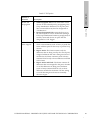
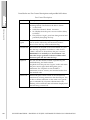
Contents of this Manual
Chapter
Introduction
Historical Traffic Monitor Window
Firmware Image Configuration
Dialog Box
Schedule Tasks Option
Trap Configuration Dialog Box
Manage Licenses Dialog Box
Switch Window
Switch Port Window
Configure the Switch Dialog Box
Describes
What is Softek SANView?
The Historical Traffic Monitor Window
The Firmware Image Configuration Dialog
Box
The Zone Scheduler Dialog Box
The Trap Configuration Dialog Box
The Manage Licenses Dialog Box
Title Bar, LED Row, and Icons, File Menu,
View Menu, Options Menu, Tools Menu,
Help Menu, Interpreting the FC4 Type
Value
Port Window
File Menu, System Tab, Time Settings Tab,
Ports Tab, Stealth-2/Stealth Tab, Stealth-3
Tab, Logging Tab, Zoning Tab, Version Info
Tab, Device Info Tab, Sensor Info Tab,
Options Tab
LICENSED MATERIAL - PROPERTY OF FUJITSU SOFTWARE TECHNOLOGY CORPORATION
xi
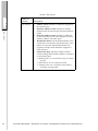
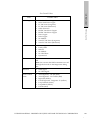
Hub Window
Port Window
Configure the Hub Dialog Box
Notation Conventions
Hub Diagnostics Dialog Box
xii
Title Bar, LED Row, and Icons, File Menu,
View Menu, Options Menu, Tools Menu,
Help Menu
Hub Port Window
File Menu, Help Menu, Zoning Tab, Policies
Tab
Sweep, Loop, and Port Tabs
Notation Conventions
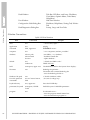
Softek SANView Notations
Item
Convention
Example
alias
text
"...device alias, tape1..."
application
text
aplpkg
command
bold, uppercase
CONNECT causes...
computer
text
"...two computers, machine_a and B1."
database
when a path
when named
else text
/aaa/bbbb/,/ccc, database...
...database named db1.
...alpha database...
default
text
underscore
"...default for TIME is NO."
TIME=YES|NO
field
monospace, upper case
The DISTRICT field on the System View display...
file name
text
Robotlog.dat performs...
The tstdata file is named Robotlog.dat.
...uses the Robotlog.dat file to...
Windows file path
text
c:\Softek SANView\tables
Unix file path and
commands
text in Courier format,
bold
/etc/init.d/volmgt stop
keyboard entry
text, uppercase
Press the ENTER key.
parameter/keyword
monospace, UPPER
CASE
PAUSE keyword...NODEID parameter...
program
text
Use Sentutil.exe to...
...uses the program named Sentutil.exe
...uses the Sentutil.exe program to...
LICENSED MATERIAL - PROPERTY OF FUJITSU SOFTWARE TECHNOLOGY CORPORATION
At different locations throughout this manual information may appear in notes as
follows:
NOTE:
This note clarifies or emphasizes text that precedes or follows it.
Notices
softek.fujitsu.com
Notices
Related Publications
The following publications contain related information.
Softek SANView User’s Guide
(ML-144912-002)
Softek SANView Software Installation & Release Notes (SIRN)
(ML-144915-002)
33
LICENSED MATERIAL - PROPERTY OF FUJITSU SOFTWARE TECHNOLOGY CORPORATION
xiii
1
Introduction
•
What is Softek SANView?
3
LICENSED MATERIAL - PROPERTY OF FUJITSU SOFTWARE TECHNOLOGY CORPORATION
1
2
LICENSED MATERIAL - PROPERTY OF FUJITSU SOFTWARE TECHNOLOGY CORPORATION
•
Automatically detects and discovers host bus adapters (HBAs) and Fibre Channel
Management Integration MIB (Fibre Alliance MIB)-compliant switches, hubs,
routers, bridges, disks, and arrays in the SAN for management; collects and
interprets management data; and allows you to launch alternate management
tools (such as Telnet or Web-based tools).
•
Monitors and displays the health of the interconnections between SAN devices.
•
Scales easily (through its advanced architecture) to accommodate updates of
Softek SANView Modules. A Softek SANView Module is a software subset that
allows Softek SANView to discover, monitor, and manage specific SAN devices.
Options include specialized discovery, data collection and interpretation,
graphical user interfaces, and launch of alternate management tools.
•
Integrates with and reports events to Enterprise Management Applications such
as CA Unicenter (when related Softek SANView Integration Module is installed).
•
Quickly troubleshoots and isolates problems through health monitoring, userfiltered event logs, and advanced diagnosis capabilities. These features help you
quickly identify, isolate, and fix issues to keep your SAN operating reliably.
•
Manages agents out-of-band to facilitate SAN management configuration, allow
remote management capability, and ensure continually available management
data (even if parts of the SAN transport are down).
•
Proactively monitors status and detects problems at every level, notifying
administrators via email when failure-marked events occur. All events are shown
in the SAN Events frame as well. The health of all SAN devices is continually
monitored and displayed.
•
Tracks bandwidth usage with configurable traffic threshold alerts for easy
capacity planning.
•
Secures both monitoring and management options through user-defined
passwords, passed between Client and Server through the MD5 encryption
algorithm. (MD5 is Message Digest 5, a public one-way hash function used for
password encryption. MD5 is defined in RFC 1321.)
•
Runs on UNIX and Windows®.
softek.fujitsu.com
Softek SANView manages heterogeneous multi-vendor SANs, streamlining SAN
management through the following features:
What is Softek SANView?
What is Softek SANView?
33
LICENSED MATERIAL - PROPERTY OF FUJITSU SOFTWARE TECHNOLOGY CORPORATION
3
2
Historical Traffic Monitor Window
•
The Historical Traffic Monitor Window
7
LICENSED MATERIAL - PROPERTY OF FUJITSU SOFTWARE TECHNOLOGY CORPORATION
5
6
LICENSED MATERIAL - PROPERTY OF FUJITSU SOFTWARE TECHNOLOGY CORPORATION
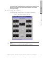
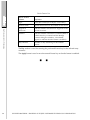
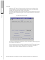
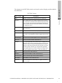
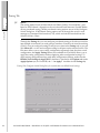
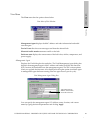
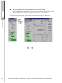
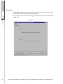
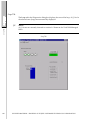
The Historical Traffic Monitor window for Vixel Switches is shown below.
Historical Traffic Monitor window for a Vixel 7200
softek.fujitsu.com
The Historical Traffic Monitor Window
The Historical Traffic Monitor Window
This section describes the information shown in Softek SANView’s Historical Traffic
Monitor dialog box, which can be opened from Vixel hub and switch windows
through the View menu.
NOTE:
Only frame data is measured; LIPs, ARBs, and IDLEs are ignored.
LICENSED MATERIAL - PROPERTY OF FUJITSU SOFTWARE TECHNOLOGY CORPORATION
7
The Historical Traffic Monitor Window
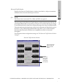
The port gauges on the Hub window, Switch window, and Historical Traffic Monitor
window measure port traffic differently depending on the device; switch gauges
display a rate while hub gauges display a percentage. The rate displayed by switch
gauges is a MB/second baud rate corresponding to both received and transmitted data
on the port. The percentage displayed by hub gauges is a portion of bandwidth
corresponding to the port’s received data only (the percentage is calculated by the
hub’s firmware as a port percentage of the loop’s total bandwidth).
This performance monitoring feature can be used to determine the bandwidth used on
the device’s loop. Monitoring the bandwidth usage allows you to make informed
decisions about the need to add devices or implement switches for increased
throughput.
NOTE:
The poll interval for traffic data is five seconds and is not affected by the Softek
SANView poll interval set through Softek SANView’s Tools menu.
You can set the port traffic threshold (rate or percentage) for triggering the Attention
and/or Overload states. Every time this threshold is exceeded, an event is recorded in
the SAN Events frame; and the appropriate icon (Attention or Overload) appears in
the Historical Traffic Monitor window above, ports that exceed the thresholds. For
Vixel Switches, thresholds correlate to the amount of port traffic—the selected point
between 0 and 200 MB/second. For Vixel Managed Hubs, thresholds correlate to the
percentage of available traffic used by the port—the selected point between 0 and 100
percent. (You can select a single percentage point by pressing an arrow key.)
The File menu allows you to close the window or exit the SANView Client.
The Options menu allows you to reset traffic threshold settings for either all Vixel
Managed Hubs or all Vixel Switches (depending on the window from which the
Historical Traffic Monitor window was opened).
The Tools menu allows you to change traffic threshold settings for either all Vixel
Managed Hubs or all Vixel Switches (depending on the window from which the
Historical Traffic Monitor window was opened).
The Help menu contains two options: Contents for online help display and About
Softek SANView... for system and version information.
The Historical Traffic Monitor window also offers the following information:
8
•
Traffic display for total of all ports.
•
Traffic display for all selected ports.
•
For Vixel Managed Hubs, traffic display for all selected zones (by port).
•
For Vixel Switches, a separate measure of port receiver and port transmitter traffic
(left and right numbers under port graphs, respectively).
•
Time Scale by the selected unit (seconds, minutes, or hours).
LICENSED MATERIAL - PROPERTY OF FUJITSU SOFTWARE TECHNOLOGY CORPORATION
•
Magnified and detached port graph; displayed when you double-click a port
graph.
To record an event every time a traffic threshold is exceeded:
•
Keep the Historical Traffic Monitor window open (minimized is okay). Events are
automatically recorded in the SAN Events frame (lower frame in Softek
SANView’s main window).
33
LICENSED MATERIAL - PROPERTY OF FUJITSU SOFTWARE TECHNOLOGY CORPORATION
softek.fujitsu.com
High water mark (the most traffic generated) on a port; displayed when you
position your cursor over a port graph.
The Historical Traffic Monitor Window
•
9
3
Firmware Image Configuration Dialog Box
•
The Firmware Image Configuration Dialog Box
13
LICENSED MATERIAL - PROPERTY OF FUJITSU SOFTWARE TECHNOLOGY CORPORATION
11
12
LICENSED MATERIAL - PROPERTY OF FUJITSU SOFTWARE TECHNOLOGY CORPORATION
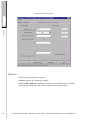
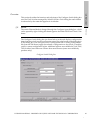
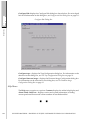
The Firmware Image Configuration Dialog Box
softek.fujitsu.com
This section describes the selections of Softek SANView’s Firmware Image
Configuration dialog box as it applies to Vixel devices. This dialog box can be opened
from Vixel hub and switch windows through the Configure firmware image... option
in the Tools menu.
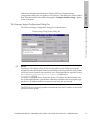
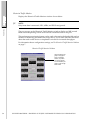
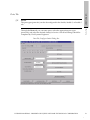
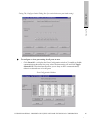
Firmware Image Configuration Dialog Box
The Firmware Image Configuration Dialog Box
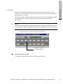
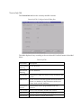
The Firmware Image Configuration dialog box is shown below.
NOTE:
The device’s IP Address (which is listed in the title bar of the dialog box) must be
included in either the Domain Name System (DNS) or the host name file on the Softek
SANView Server system for file transfer to occur. Host name files are typically located
in C:\WINNT\system32\drivers\etc\Hosts [Windows] or
/etc/hosts [UNIX].
To register a managed device, obtain the device’s IP Address and device name from
the system administrator, open the host name file in an editor (such as Notepad), type
the device’s IP Address and device name (on one line), and save the file.
The TFTP Host IP (read-only) textbox automatically lists the IP Address of the Softek
SANView Server system.
LICENSED MATERIAL - PROPERTY OF FUJITSU SOFTWARE TECHNOLOGY CORPORATION
13
The Firmware Image Configuration Dialog Box
NOTE:
For files to be transferred, the TFTP client must initialize correctly on port 69 when the
Softek SANView Server is started. Otherwise an error message is displayed when
Download is clicked. (TFTP client initialization errors are recorded in the
SIServer.err file, which is located in install_dir/bin, where install_dir is the
installation directory.)
•
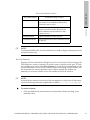
The selections in the Firmware Image Configuration dialog box are described
below.
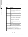
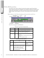
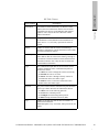
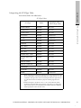
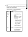
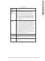
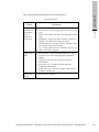
Firmware Image Configuration Dialog Box Selections
Selection
Function
File Name^
Allows you to enter the path and filename of the
desired firmware image file. The combined path and
filename are limited to 128 characters, starting from
and including the deviceconf/ directory.
Browse
Allows you to search for the firmware image file
within the appropriate vendor directory.
Set Boot
Image
Allows you to choose the desired image for
activation upon agent reset.
Download
Transfers file (through TFTP) to the device.
Abort
Download
Stops the file transfer.
Help
Displays Softek SANView online help.
^ All firmware image files are accessed from the appropriate vendor
directory in*:
(Windows) C:\SANView\SIFileSystemRoot\deviceconf\
• (UNIX) /opt/SANView/SIFileSystemRoot/deviceconf/
*Files are located on the Softek SANView Server system. The listed locations
assume that the default installation directory for Softek SANView was
accepted and that Softek SANView’s Root Directory parameter is
unchanged. (By default, Softek SANView’s Root Directory is named
“SANView” and is placed inside the accepted installation directory.)
33
14
LICENSED MATERIAL - PROPERTY OF FUJITSU SOFTWARE TECHNOLOGY CORPORATION
4
Schedule Tasks Option
•
The Zone Scheduler Dialog Box
17
LICENSED MATERIAL - PROPERTY OF FUJITSU SOFTWARE TECHNOLOGY CORPORATION
15
16
LICENSED MATERIAL - PROPERTY OF FUJITSU SOFTWARE TECHNOLOGY CORPORATION
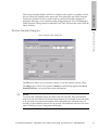
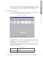
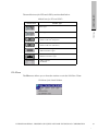
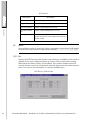
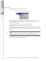
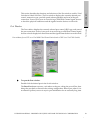
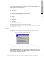
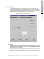
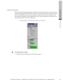
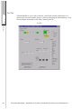
The Zone Scheduler Dialog Box
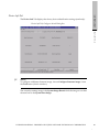
Zone Scheduler View Dialog Box
softek.fujitsu.com
The Zone Scheduler Dialog Box
This section describes Softek SANView’s Schedule tasks option as it applies to Vixel
devices. When the Schedule tasks option and Vixel sub-option are chosen from the
Tools menu (Softek SANView’s main window), the Zone Scheduler dialog box is
displayed, allowing you to schedule zoning configurations for Vixel 2100 Managed
Hubs (when the Zoning feature is enabled), Vixel 7100/7200 Switches, and Vixel 8100
Fabric Switches.
The File menu allows you to close the window or exit the Softek SANView Client.
The Help menu contains two options: Contents for online help display and About
Softek SANView... for system and version information.
NOTE:
To ensure that scheduled zoning and other tasks are executed, base the Scheduler
interval on the task with the lowest time measurement. For example, if one task needs
to be executed every 60 seconds and the other task needs to be executed every 30
seconds, set the Scheduler interval for 30 seconds. The Scheduler interval is set in the
Softek SANView Server Configuration dialog box.
LICENSED MATERIAL - PROPERTY OF FUJITSU SOFTWARE TECHNOLOGY CORPORATION
17
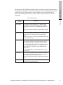
•
The selections under Edit Selected Item (bottom area of dialog box) are described
below.
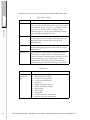
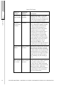
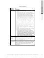
Selections Under Edit Selected Item
The Zone Scheduler Dialog Box
Selection or
Textbox
Description
Device IP
Drop-down list of monitored hubs and
switches on which zoning is supported.
Persistent
When checked, ensures that the zoning
configuration remains when power is cycled to
the hub or switch.
Enabled
When checked, allows scheduled zoning to
occur at specified time(s).
Zone File^
Drop-down list of available zone configuration
files.
Run Options
Determines how often the zoning
configuration is applied to the hub or switch.
Start At
Determines the time and day at which the
zoning configuration is applied to the hub or
switch.
Add New Item
Creates an entry in the “Items Available in the
Zone Scheduler” list with the specified
settings.
Remove Selected
Item
When an entry within the “Items Available in
the Zone Scheduler” list is selected, deletes
that entry.
Update Selected
Item
When an entry within the “Items Available in
the Zone Scheduler” list is selected, applies all
settings configured within the Edit Selected
Item area (bottom half of dialog box).
^ All device configuration files are saved to the appropriate vendor directory
in*:
•
(Windows) C:\SANView\SIFileSystemRoot\deviceconf\
•
(UNIX) /opt/SANView/SIFileSystemRoot/deviceconf/
*Files are located on the Softek SANView Server system. The listed locations
assume that the default installation directory for Softek SANView was accepted
and that Softek SANView’s Root Directory parameter is unchanged. (By default,
Softek SANView’s Root Directory is named “SANView” and is placed inside the
accepted installation directory.)
33
18
LICENSED MATERIAL - PROPERTY OF FUJITSU SOFTWARE TECHNOLOGY CORPORATION
5
Trap Configuration Dialog Box
•
The Trap Configuration Dialog Box
21
LICENSED MATERIAL - PROPERTY OF FUJITSU SOFTWARE TECHNOLOGY CORPORATION
19
20
LICENSED MATERIAL - PROPERTY OF FUJITSU SOFTWARE TECHNOLOGY CORPORATION
NOTE:
The trap-listening process requires registration of devices in either the Domain Name
System (DNS) or the host name file on the Softek SANView Server system. Host name
files are typically located in C:\WINNT\system32\drivers\etc\Hosts
[Windows] or /etc/hosts [UNIX].
To register a managed device, obtain the device’s IP Address and device name from
the system administrator, open the host name file in an editor (such as Notepad), type
the device’s IP Address and device name (on one line), and save the file.
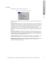
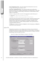
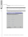
The Trap Configuration Dialog Box
The Trap Configuration Dialog Box is shown on the next page.
LICENSED MATERIAL - PROPERTY OF FUJITSU SOFTWARE TECHNOLOGY CORPORATION
softek.fujitsu.com
The Trap Configuration Dialog Box
This section describes the selections of Softek SANView’s Trap Configuration dialog
box, which can be opened from the Vixel hub and switch windows through the
Configure traps... option in the Tools menu.
21
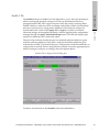
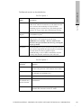
The Trap Configuration Dialog Box
Trap Configuration Dialog Box
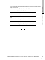
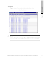
The “Trap List” (upper portion of the dialog box) lists an entry for each configured trap
destination. The “Trap List” columns are defined below.
Trap List
22
Trap List column
Definition
IP Address
IP Address of the destination system.
Port
Port of the destination system that is configured to
listen for traps.
Community String
Password, if applicable.
Severity Level
The type of event messages that you want to trigger
traps. For example, selection of the “alert” severity
level configures traps to be sent only when event
messages of the “alert” severity or higher occur.
(Severity level configuration is not available for
Vixel 8100.)
LICENSED MATERIAL - PROPERTY OF FUJITSU SOFTWARE TECHNOLOGY CORPORATION
The selections under Edit Select Item are described below.
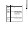
Selections Under Edit Select Item
Selection
Description
Add New Item
Adds the entered information to the Trap List as
an entry.
Remove Selected
Item
Deletes the selected entry.
Update Selected
Item
Changes the selected entry with the entered
information.
Apply
Saves the trap configurations onto the agent.
Discard
Cancels any trap configurations made since the
Trap Configuration dialog box opened.
Help
Displays Softek SANView online help.
softek.fujitsu.com
•
The Trap Configuration Dialog Box
The textboxes under Edit Selected Item (bottom area of dialog box) match the columns
of the above Trap List.
33
LICENSED MATERIAL - PROPERTY OF FUJITSU SOFTWARE TECHNOLOGY CORPORATION
23
6
Manage Licenses Dialog Box
•
The Manage Licenses Dialog Box
27
LICENSED MATERIAL - PROPERTY OF FUJITSU SOFTWARE TECHNOLOGY CORPORATION
25
26
LICENSED MATERIAL - PROPERTY OF FUJITSU SOFTWARE TECHNOLOGY CORPORATION
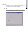
When the Vixel module is chosen, the Manage Licenses dialog box is displayed, which
allows you to enable purchased features such as hard zoning.
Manage Licenses Dialog Box
softek.fujitsu.com
The Manage Licenses Dialog Box
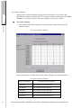
The Manage Licenses Dialog Box
This section describes Softek SANView’s Manage Licenses dialog box as it applies to
Vixel devices. This dialog box is opened through the Manage Licenses option (under
the Vixel sub-option) in the Tools menu of Softek SANView’s main window.
The File menu allows you to close the window or exit the Softek SANView Client.
The Help menu contains two options: Contents for online help display and About
Softek SANView... for system and version information.
The Device Feature list (upper portion of the dialog box) lists an entry for each
detected Vixel device that has separate feature options. The columns in the Device
Feature list are defined below.
Device Feature List
Device Feature
column
Definition
Device IP
IP Address of the detected Vixel device.
LICENSED MATERIAL - PROPERTY OF FUJITSU SOFTWARE TECHNOLOGY CORPORATION
27
The Manage Licenses Dialog Box
Device Feature List
Device Feature
column
Definition
Type
Vixel device name (for example, “Vixel 7200").
Feature Name
Specific feature that can be enabled on this device.
Support in
Firmware
Indicates whether said feature is supported in the
current firmware.
Enabled
Indicates whether said feature is enabled. (When a
valid license key is entered and the Manage
Licenses dialog box refreshes, a checkmark
appears to indicate that the feature is enabled.)
Days Remain
Number of days remaining on this enabled
feature.
The Key textbox is used for entering the purchased license key for the selected entry
or entries.
The Apply button is used to save the entered license key so that the feature is enabled.
33
28
LICENSED MATERIAL - PROPERTY OF FUJITSU SOFTWARE TECHNOLOGY CORPORATION
7
Switch Window
•
Overview
31
•
Title Bar, LED Row, and Icons
32
•
File Menu
33
•
View Menu
34
•
Options Menu
52
•
Tools Menu
53
•
Help Menu
54
•
Interpreting the FC4 Type Value
55
LICENSED MATERIAL - PROPERTY OF FUJITSU SOFTWARE TECHNOLOGY CORPORATION
29
30
LICENSED MATERIAL - PROPERTY OF FUJITSU SOFTWARE TECHNOLOGY CORPORATION
The Switch window identifies each port of the switch, the types of modules installed
(when applicable), and the health of the switch ports and internal hardware
(enclosures).
NOTE:
The switch Ethernet Mode is changed through the Configure Agent dialog box, which
can be opened by right-clicking the related agent in the SANView Client’s Tree frame.
softek.fujitsu.com
This section describes the functions and selections of Softek SANView’s switch
window for Vixel Switches. Each dialog box and window is referred to by the name
that appears in its title bar.
Overview
Overview
Switch Window for a Vixel 7200 Fibre Channel Switch
Double-click a port graphic
to view its Port window.
To open the Switch window
•
Double-click the desired switch icon in the main window.
LICENSED MATERIAL - PROPERTY OF FUJITSU SOFTWARE TECHNOLOGY CORPORATION
31
Title Bar, LED Row, and Icons
Title Bar, LED Row, and Icons
The title bar of the Switch window lists (from left to right): Agent Type (Switch),
System Name in quotes (user-configured), Serial Number in brackets, IP Address, and
World-wide Name (WWN). The LED row under the menus lists (from left to right):
Model Number, Serial Number, Power LED, Environmental LED, and Reset Fault
LED.
Switch window for a Vixel 7100, with explanatory call-outs for title bar and LED row
The LED color legend is described below.
LED Color Legend of the Switch Window
Switch LED
Green
Yellow
Power
OK
N/A—switch will not display if powered off.
Environmental
OK
• Fan fault—fan(s) have stopped operating.
• Over temperature warning or fault.
Reset Fault
N/A
• Internal switch failure—an internal failure was
detected.
• Self-test failure—POST failed and the system needs
attention.
• Incorrect configuration loaded.
Port LED of the Switch Window
Port LED
32
On
Off
Green
(top)
The inserted module is healthy (normal
operation).
Either there is no module
inserted, or the module is
unhealthy.
Yellow
(bottom)
The port is bypassed due to a problem
detected by either the module’s transmit
logic or the module receiver. Receiver
problems include unconnected fiber,
remote node not transmitting, LIP(F8), or
a faulty module receiver.
The port is not bypassed.
(normal operation)
LICENSED MATERIAL - PROPERTY OF FUJITSU SOFTWARE TECHNOLOGY CORPORATION
Module Icon
Module Type
Intra Copper
Inter Copper
• FC LW Laser (Longwave)
• Serial FC LW Laser (Longwave)
softek.fujitsu.com
Module Icons for SFPs and GBICs
File Menu
The module icons (for SFPs and GBICs) are described below.
• FC SW Laser (Shortwave)
• Serial FC SW Laser (Shortwave)
• DB-9 Serial Intra Copper
• DB-9 Serial Inter Copper
• HSSDC Serial Intra Copper
• HSSDC Serial Inter Copper
• GBIC Unknown
• No Module
File Menu
The File menu allows you to close the window or exit the SANView Client.
File Menu of the Switch Window
LICENSED MATERIAL - PROPERTY OF FUJITSU SOFTWARE TECHNOLOGY CORPORATION
33
View Menu
The View menu has the options shown below.
View Menu
View menu (Switch Window), for a Vixel 7100 running V. 3.0 firmware (FSPF Routing table used)
Device Events lists the event messages read from the selected switch.
Port Frame statistics... counts frames (such as “C2Discards”) for each port.
Port Link statistics... counts occurrences of certain events or signals for each port.
FSPF Routing table or RIP table characterizes paths to other switches and lists the
domain numbers of the destination switches.
NOTE:
The available option (FSPF or RIP) is determined by the switch routing protocol, which
depends on switch model and firmware version. Some switches use FSPF while others
use RIP. Vixel 9000 Series Switches use FSPF only.
SNS table displays information for devices that are registered with the switch
Historical traffic monitor measures the traffic on the switch.
Enclosure state displays the current status of the switch fans, airflow, temperature,
power supply, and battery.
34
LICENSED MATERIAL - PROPERTY OF FUJITSU SOFTWARE TECHNOLOGY CORPORATION
Displays the Device Events window for the switch, as shown below.
View Menu
Device Events Window
softek.fujitsu.com
Device Events
NOTE:
Network drives can be accessed only if they are mapped to a drive letter. In file names,
avoid the following characters (separated by commas): \, /, :, *, ?, “, <, >, {, }, [, ], (, ), |.
LICENSED MATERIAL - PROPERTY OF FUJITSU SOFTWARE TECHNOLOGY CORPORATION
35
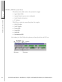
Port Frame Statistics
Displays the Port Frame Statistics dialog box (shown below). You can save this
information to a file (see the File menu). To clear the counters on the switch, click Clear
Counters. To see more columns, move the scrollbar or resize the window.
To reorder columns:
View Menu
•
Click and hold the left mouse button on the desired column and drag to the
desired location.
Port Frame Statistics Window
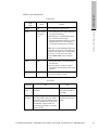
Port Frame Statistics columns are listed in order of display and described below.
Port Frame Statistics Columns
Port Frame Statistic
36
Occurrences Being Counted
C2InFrames
Class 2 frames received by this port.
C2OutFrames
Class 2 frames leaving by this port.
C3InFrames
Class 3 frames received by this port.
C3OutFrames
Class 2 frames leaving by this port.
C2Discards
Class 2 frames thrown out by this port.
LICENSED MATERIAL - PROPERTY OF FUJITSU SOFTWARE TECHNOLOGY CORPORATION
Occurrences Being Counted
C2FbsyFrames
Class 2 frames thrown out by this port because this
port already has an established communication
with another port (it’s busy).
C2FrjtFrames
Class 2 frames rejected by this port. Frames are
usually rejected because they did not pass the
frame validation inspections inherent in Fibre
Channel protocol.
GenlStatRxABTS
ABTS commands received by this port.
GenlStatRxFCPcmds
Fibre Channel Protocol (FCP) commands received
by this port.
softek.fujitsu.com
Port Frame Statistic
View Menu
Port Frame Statistics Columns
NOTE:
To minimize SNMP traffic, the Port Link Statistics window displays data for ports with
inserted modules only.
Port Link Statistics
Displays the Port Link Statistics dialog box (see Port Link Statistics Window on page 38).
This dialog box counts occurrences of certain events or signals for each port. To clear
the counters on the switch, click Clear Counters. You can save this information to a file
(see the File menu). The saved file contains caption, timestamp, column headers, and
all counter data in comma-separated values with an Append file attribute (on
demand). To see more columns, move the scrollbar or resize the window.
NOTE:
Network drives can be accessed only if they are mapped to a drive letter. In file names,
avoid the following characters (separated by commas): \, /, :, *, ?, “, <, >, {, }, [, ], (, ), |.
To reorder columns:
•
Click and hold the left mouse button on the specified column and drag to the
desired location.
LICENSED MATERIAL - PROPERTY OF FUJITSU SOFTWARE TECHNOLOGY CORPORATION
37
View Menu
Port Link Statistics Window
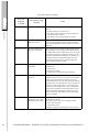
The Port Link Statistics columns are listed in alphabetical order and described in the
following table.
38
LICENSED MATERIAL - PROPERTY OF FUJITSU SOFTWARE TECHNOLOGY CORPORATION
Occurrences being
Counted
Notes
ActDev
Devices that this port has
discovered during loop
initialization.
---
Failure
Link failure events.
N_Port State machine signaling remote has disconnected
or has not responded in time, indicating a problem with the
remote device. This counter is a long-term event counter,
incrementing only once even if the condition persists. A
link failure event occurs when one of the following events
occurs:
• A loss of synchronization.
• Link reset protocol.
• A Not Operational (NOS) primitive sequence is
received.
• A loss of signal occurs in an illegal state.
InvTxWord
Instances of link corruption.
Causes of link corruption follow:
• code violation (invalid transmit word).
• framing error.
• improper beginning running disparity.
LinkTo
Expiration of the protocol
timer E_D_TOV during
protocol state change on
the line.
A switch port’s timer may expire if it is much faster than
the remote device. To resolve this speed discrepancy,
either increase the remote device’s speed or increase the
switch time-out period (change the EDTOV setting
through the Ports tab of the Configure Switch dialog box).
LoopConnTO
Loop Connection Time
Out.
This counter increments when remote devices do not
acknowledge protocol within the configured time limit.
Time-outs indicate a need to increase the remote device’s
speed. Frequent time-out will definitely affect performance.
PrimSeqErr
Detected primitive
sequence errors received.
Primitive sequence errors indicate that the remote device is
violating protocol. In most cases the switch port discards
the primitive. If the attached device has done its homework, this counter increments very rarely.
PRLIResp
Devices on this port that
responded to the PRLI
probe for FC4 Types.
---
RxClkLoss
Loss of receive clock.
The switch does not lose receive clock. (This hardware
signal was designed to have an external sync indicator in a
future release.)
LICENSED MATERIAL - PROPERTY OF FUJITSU SOFTWARE TECHNOLOGY CORPORATION
softek.fujitsu.com
Port Link
Statistics
Columns
View Menu
Port Link Statistics Columns
39
Port Link Statistics Columns
View Menu
Port Link
Statistics
Columns
40
Occurrences being
Counted
Notes
RxCrcErr
Receipt of CRC errors.
Receipt of CRC errors can be caused by the following conditions:
• Internal problems on a remote device.
• Link data corruption caused by a generous number of
InvTxWords on the same line.
• Bad cabling or other electromagnetic interference.
RxFIFOOverRun
Receipt of more data than
FIFO has room for.
Contact an authorized service representative if FIFO errors
occur. Any FIFO problem must be attended to immediately. Internal adjustment will be necessary to correct this
indication.
RxFrameTooLong
Receipt of a frame longer
than the set maximum.
This occurrence can be caused by a discrepancy in maximum settings; the switch setting for maximum frames may
be smaller than the device setting. In this case, the counter
increments in large bursts as full device frames are sent.
Note that not all frames are full frames. For example, command type frames are usually much smaller than full
frames. Device discovery may complete and appear to
work until large frames are passed.
RxFrameTooShort
Receipt of a truncated
short frame.
Truncated short frames should occur infrequently. Possible
causes follow:
• Protocol reset.
• Remote device failure.
• Extreme noise or external disruption (unlikely).
RxLinkResets
Receipt of N_Port LR
primitives.
A device has sent N_Port LR primitives to the switch, indicating that protocol errors are occurring. This is a Switch
to device peer level indicating some type of recovery
needed. If frequent resets occur, then a possible credit mismatch may be a cause. Link failure is also recorded in message logs, as well as Trap if set up. For cascade switch
ports in one of the Stealth Modes, a N_Port LR primitive
indicates that a target device has passed a LIP (Loop Initialization Primitive) propagation to initiator device(s);
that is, the LIP If Storage Added option (in Softek SANView) was enabled.
RxMissingDelims
Received FIFO data has a
frame that is not properly
delimited by SOF or EOF.
Missing delimiters in received FIFO data can be caused by
the following conditions:
• Recover event to a very slow or delinquent remote
device (most common).
• A Rcv FIFO overrun.
• Internal corruption or faulty firmware (least common).
LICENSED MATERIAL - PROPERTY OF FUJITSU SOFTWARE TECHNOLOGY CORPORATION
Occurrences being
Counted
Notes
RxOls
Receipt of N_Port OLS.
A received N_Port OLS indicates that a connected device
went into an Off-Line state—that is, although the device is
still powered on, it is not operational because the upper
level needs recovery time before data can be transmitted or
received. Frequent OLS states indicate that the devices
were able to establish connection. Then, loose connection
long enough for protocol reset to also fail. This should be
an infrequent event unless connections are being disrupted
at the protocol level. Note: Received N_Port OLS primitives invoke the Registered State Change Notification,
which prompts hosts to update their device information
through the switch SNS table (see “SNS Table” on
page 48).
RxOpenCLS
Receipt of a CLS by the
port OPN.
The remote device on the loop is generating a CLS to the
port OPN. This indicates that a device is not allowing the
port to send data to it. If the counter increases, attempts to
send data out the port are affected and performance begins
to lower.
SelfReg
Public devices on this port
that automatically registered with the Directory
Server and indicated their
FC4 type.
---
SignalLoss
Loss of signal.
The loss of signal indicates it is unable to find and follow
the Rx Clock. The switch port will constantly attempt to
find the Rx clock with the assist of the Firmware code. If
the counter is changing frequently, this may indicate that
the device attached clock or our reference clock is not stable. When initially connected, a few Signal loss may be
indicated as a wiggling cable insertion will be in and out of
alignment for a few seconds.
SyncLoss
Transitions of the physical level from a synchronization-acquired state to a
loss of synchronization
state.
The switch port is unable to find ordered sets. Until Signal
is found, this counter will not change. Sync loss can occur
if the data still follows Disparity but does not send Ordered
sets. This is very rare and will most likely follow the Signal Loss of Link Failure.
TxCLSOpen
Transmission of a CLS
(close) after receiving an
OPN (open).
This counter increments when the port does not allow the
remote device to send data to it, indicating that the Rx
FIFO is full or busy. Frames in the queue are being held
due to a destination device not servicing frames. Frames
then back up in the destination port Tx queue until it does
not allow the router to send more; then the frames begin to
back up in the RX queue FIFO changing the CLS to an
OPN. This is a good indicator that a slow servicing device
may need tuning of data IO request size or Framing Size.
LICENSED MATERIAL - PROPERTY OF FUJITSU SOFTWARE TECHNOLOGY CORPORATION
softek.fujitsu.com
Port Link
Statistics
Columns
View Menu
Port Link Statistics Columns
41
Port Link Statistics Columns
Port Link
Statistics
Columns
Occurrences being
Counted
TxCrcErr
Transmission of CRC
errors.
Switch-wide, the amount of transmitted CRC errors usually equals the amount of received CRC errors. If the
switch (that is, the sum of all ports) has transmitted more
CRC errors than it has received, the module or switch may
have an internal problem. To find out whether the module
is causing the problem, isolate the problem to a port, then
to the module. To find out whether the switch has an internal problem, check for the following conditions:
• Voltage problems or noise on A/C power.
• Non-optimum temperature (see the fans).
If the switch has an internal problem, contact an authorized
service representative.
TxFIFOUnderRun
Transmission of less data
than FIFO expected.
Contact an authorized service representative if FIFO errors
occur. Any FIFO problem must be attended to immediately. Internal adjustment will be necessary to correct this
indication.
TxLinkResets
Transmission of N_Port
LR primitives.
A switch has sent N_Port LR primitives to the connected
device(s), indicating that protocol errors are occurring.
This is a Switch to device peer level indicating some type
of recovery needed. If frequent resets occur, then a possible credit mismatch may be the cause. Link failure is also
recorded in message logs, as well as Traps, if set up.
TxMissingDelims
Transmitted FIFO data has
a frame that is not properly delimited by SOF or
EOF.
Missing delimiters in transmitted FIFO data can be caused
by the following conditions:
• Recover event to a very slow or delinquent remote
device (most common).
• Frames being aborted and truncated because they get
stuck during a route recover. (Some route recovers use a
frame Disconnect time-out event that can generate a
missing Tx delimiter.) If this happens frequently, the port
and system performance is affected.
• Internal corruption or faulty firmware (least common).
View Menu
42
Notes
LICENSED MATERIAL - PROPERTY OF FUJITSU SOFTWARE TECHNOLOGY CORPORATION
Occurrences being
Counted
Notes
TxOls
Transmission of N_Port
OLS.
A transmitted N_Port OLS indicates that the switch went
into an Off-Line state—that is, although the switch is still
powered on, it is not operational because the upper level
needs recovery time before data can be transmitted or
received. Frequent OLS states indicate that the devices
were able to establish connection. Then, loose connection
long enough for protocol reset also fail. This should be an
infrequent event unless connections are being disrupted at
the protocol level.
TxParityErr
Parity error on the switch
port.
Any Parity must be reported and corrected immediately.
This parity error has the following indications:
• The switch port is receiving Data over the internal bus
with invalid Parity.
• The internal hardware may have failed.
TxTagErr
Bad tag.
This is an indication that the switch port is receiving Data
over the internal bus with bad Tags. The Bad Tag can be
caused by incoming corrupted Frames, which is indicated
by an Invalid Tag marker. Much link Parity, a tag is associated to each word in the frame. An internal hardware error
of the Tag bits is highly unlikely but still possible. Look
for other ports with link problems that might cause Frames
to be forward with bad tag to another port.
softek.fujitsu.com
Port Link
Statistics
Columns
View Menu
Port Link Statistics Columns
NOTE:
Network drives can be accessed only if they are mapped to a drive letter. In file names,
avoid the following characters (separated by commas): \, /, :, *, ?, “, <, >, {, }, [, ], (, ), |.
LICENSED MATERIAL - PROPERTY OF FUJITSU SOFTWARE TECHNOLOGY CORPORATION
43
RIP Table
Displays the RIP Table and Statistics window (shown below). Availability of this
window depends on the switch model and firmware version. The switch must be
running Fabric Mode and Fabric (Public/Private) Mode.
View Menu
This window identifies the other switches that the switch can communicate with, and
characterizes the communication paths. You can save this information to a file (see the
File menu).
RIP Table and Statistics Window
The columns in the RIP Table and Statistics window are listed in order of display and
are described in the table below.
Note that the selected switch is identified in the title bar of the RIP Table and Statistics
window; each destination switch is identified in the Destination column (by its
domain or fabric address, represented by the first two characters).
44
LICENSED MATERIAL - PROPERTY OF FUJITSU SOFTWARE TECHNOLOGY CORPORATION
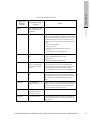
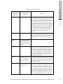
Description
Destination
A destination switch (identified by its domain or fabric
address) that can communicate with the selected switch
(identified in the title bar of the RIP Table and Statistics
window). Note: Only the first two characters contain
address information.
Port Index
The port in the selected switch that can communicate with
the destination switch (identified in the Destination column). Note: A “0” (zero) entry represents the selected
switch.
Metric
Number of switches that the selected switch must go
through to communicate with the destination switch (identified in the Destination column).
Next Hop
The next switch (identified in this column by its domain or
fabric address) that the selected switch must go through to
communicate with the destination switch (identified in the
Destination column). Note: Only the first two characters
contain address information.
Type
The communication path that the selected switch uses to
reach the destination switch. Communication paths are
identified as follows.
• 1 = Other: the route is through the selected switch only
• 2 = Invalid: the route is not valid
• 3 = Direct: the route is through a directly connected
switch domain in the same fabric region
• 4 = Indirect: route to a non-local connected switch
domain in the same fabric region
Protocol
The protocol that found the communication path identified
in the Type column. Protocols are identified as follows.
• 1 = Other: none of the following protocols
• 2 = Local: Fibre Channel protocol
• 3 = NetMgmt: network management protocol
• 4 = RIP: Routing Information Protocol (RIP)
Age
Number of seconds since this line has been added to or
updated in the RIP table.
Note: RIP updates every 30 seconds; other protocols do not
update.
LICENSED MATERIAL - PROPERTY OF FUJITSU SOFTWARE TECHNOLOGY CORPORATION
softek.fujitsu.com
RIP Columns
View Menu
RIP Table Columns
45
RIP Statistics
View Menu
RIP Statistic
Description
Input Packets
Number of RIP packets received.
Output Packets
Number of RIP packets sent out.
Input Good Packets
Number of good RIP packets received.
Input Discard Packets
Number of discarded RIP packets received.
Polling interval
Determines the length of time between polls. The polling interval can be set to any length of time between 5
and 305 seconds.
NOTE:
Network drives can be accessed only if they are mapped to a drive letter. In file names,
avoid the following characters (separated by commas): \, /, :, *, ?, “, <, >, {, }, [, ], (, ), |.
FSPF Table
Displays the FSPF Routing Table window (shown below). Availability of this window
depends on the switch model and firmware version. The switch must be running
Fabric Mode and Fabric (Public/Private) Mode. This window identifies the other
switches that the switch can communicate with and characterizes the communication
paths. You can save this information to a file (see the File menu).
FSPF Routing Table Window
46
LICENSED MATERIAL - PROPERTY OF FUJITSU SOFTWARE TECHNOLOGY CORPORATION
FSPF
Columns
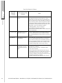
Description
Destination
A destination switch (identified by its domain or fabric
address) that can communicate with the selected switch
(identified in the title bar of the FSPF Routing Table window).
Note: Only the first two characters contain address information.
Port Number
The port in the selected switch that can communicate with
the destination switch (identified in the Destination column).
Note: An entry of “0” (zero) entry represents the table entry
for the selected switch.
Cost
Burden of this path to the destination switch. Cost is typically related to the number of switches that the selected
switch must go through to communicate with the destination switch. Frames are routed via the path with the lowest
cost, or “lightest burden.” (Cost = S * (1.0625e12 / link
speed in bits per second) where S is an administratively
defined factor.
For more information, see the OSRP specification at the
T11 website.)
Next Hop
The next switch (identified in this column by its domain or
fabric address) that the selected switch must go through to
communicate with the destination switch.
Note: Only the first two characters contain address information.
Age
Number of seconds since this line has been added to or
updated in the FSPF Routing Table.
LICENSED MATERIAL - PROPERTY OF FUJITSU SOFTWARE TECHNOLOGY CORPORATION
softek.fujitsu.com
FSPF Table Columns
View Menu
The columns in the FSPF Routing Table window are listed in order of display and are
described in the table below. Note that the selected switch is identified in the title bar
of the FSPF Routing Table window; each destination switch is identified in the
Destination column (by its domain or fabric address, represented by the first two
characters).
47
SNS Table
Displays the SNS Table (available for Fabric Mode and Fabric (Public/Private)
Mode)(shown below). This window displays information for devices that are
registered with the switch. Devices that automatically send registration to SNS (Simple
Name Server) include hosts and drives. You can save this information to a file (see the
File menu).
View Menu
SNS Table Window
NOTE:
Devices on communication-disabled ports (“Denied” ports in the Zoning
Configuration Table window) may appear in the SNS table even though the portbased zoning is supported.
Each device is identified in the NodeName column; the device port is identified in the
PortName column. The switch port to which the device is connected is identified in
two columns: the Index column (as the port number) and the Identifier column (as its
Fibre Channel address). To find out whether a device in this window supports SCSIFCP, see the SCSI-FCP column, which is the last column on the right—move the
bottom scroll bar.
48
LICENSED MATERIAL - PROPERTY OF FUJITSU SOFTWARE TECHNOLOGY CORPORATION
SNS Columns
Description
Index
Number of switch port to which this device is connected.
Identifier
Fibre Channel (three-byte) address identifying the location of
the switch-device connection. Each character represents a half
byte, or four bits. The first and second characters identify the
switch (Domain) while the third and fourth characters identify
the switch port (Area).
PortName
Name of this connected device’s port; uniquely identifies the
port on the device.
NodeName
Name of this connected device; uniquely identifies the device.
ClassOfSvc
The classes of service supported by this connected device (1, 2,
3, F). Note: Vixel 8100 Fabric Switches support classes 2 and 3
only.
NodeIPAddress
The node’s IPv6 formatted address for this connected device.
ProcAssoc
Process Associator for this connected device.
FC4Type
FC-4 types supported by this connected device (displayed as 32
characters in hex format). SCSI-FCP support is specified in the
SCSI-FCP column. To find out whether another FC-4 type is
supported, follow the instructions below this table to perform
an AND operation with the type’s mask and the appropriate
word (eight-character set) in the 32-character FC4Type value.
The type is supported if the result is a value other than zero.
Type
Port type for this connected device.
IPAddress
IPv6 formatted address of this connected device.
FabricPortName
Name of the fabric port for this connected device.
HardAddress
Hard address for this connected device.
SCSI-FCP
Specifies whether this connected device supports SCSI-FCP
(“Yes” or “No”).
LICENSED MATERIAL - PROPERTY OF FUJITSU SOFTWARE TECHNOLOGY CORPORATION
softek.fujitsu.com
SNS Table Columns
View Menu
The columns in the SNS Table window are listed in order of display and described in
the table below.
49
Historical Traffic Monitor
Displays the Historical Traffic Monitor window shown below.
View Menu
NOTE:
Only frame data is measured; LIPs, ARBs, and IDLEs are ignored.
The port gauges on the Historical Traffic Monitor window display a a MB/second
baud rate corresponding to both received and transmitted data on the port.
This performance monitoring feature can be used to determine the bandwidth used on
the device. Monitoring the bandwidth usage allows you to make informed decisions
about the need to add devices or implement switches for increased throughput.
For information about configuration settings, see The Historical Traffic Monitor Window
on page 7.
Historical Traffic Monitor Window
Click the desired port
graph to magnify its
size in a separate
window, or position
your mouse pointer
over the desired port
graph to view its high
water marks.
50
LICENSED MATERIAL - PROPERTY OF FUJITSU SOFTWARE TECHNOLOGY CORPORATION
Displays the current status of the switch fans, airflow, temperature, power supply, and
battery in the Enclosure State window shown below.
View Menu
Enclosure State Window
softek.fujitsu.com
Enclosure State
For Vixel 9000 Series Switches (switches with redundant power supplies), the possible
values for the “Power Supply 1” and “Power Supply 2” fields are as follows:
•
On (green)
•
Off (yellow)
•
Absent (gray).
A value of Off means that the power supply is either not plugged in or not operational.
LICENSED MATERIAL - PROPERTY OF FUJITSU SOFTWARE TECHNOLOGY CORPORATION
51
Options Menu
The Options menu has the options shown below.
Options Menu
Options menu for a Vixel 7100 Switch window
Show Port gauges allows you to show or hide the port gauges under each port to
display traffic rates. For more information on traffic rates, see The Historical Traffic
Monitor Window on page 7.
Activate backup fan (Vixel 8100 only) turns on the backup fan.
Reset Switch allows you to execute a soft reset of the switch.
Reset Switch with Factory Defaults (not available for Vixel 8100) allows you to apply
the factory default (as-shipped) switch configuration settings and execute a soft reset
of the switch.
NOTE:
Selecting this option will not impact the existing switch IP Address settings.
Clear Events deletes all event messages that are stored on the switch (note that the
switch continues to generate event messages).
52
LICENSED MATERIAL - PROPERTY OF FUJITSU SOFTWARE TECHNOLOGY CORPORATION
The Tools menu has the options shown below.
Tools Menu
Tools menu for a Vixel 9100 Switch window
softek.fujitsu.com
Tools Menu
Poll now immediately polls the switch for information instead of waiting for the next
poll interval.
Configure Switch... displays the Configure Switch dialog box, which reads and shows
configuration items from the switch (see the configuration status line at the bottom of
the Configure Switch Dialog Box on page 54). In this dialog box, you can open and save
a configuration file or the factory default configuration, apply (download) a
configuration to the switch, or read the switch current configuration again. For an indepth look at all information in this dialog box, see Configure the Switch Dialog Box on
page 63.
Launch Web Manager (available for switches that use WWN zoning; grayed out if
WWN zoning switch is in one of the Stealth Modes) opens the switch Web Manager
for WWN zoning and other configuration. For information on the Web Manager, see
the documentation that shipped with the switch.
Configure traps displays the Trap Configuration dialog box. For information on the
selections in this dialog box, see The Trap Configuration Dialog Box on page 21.
Configure firmware image... displays the Firmware Image Configuration dialog box.
For information on the selections in this dialog box, see The Firmware Image
Configuration Dialog Box on page 13.
LICENSED MATERIAL - PROPERTY OF FUJITSU SOFTWARE TECHNOLOGY CORPORATION
53
Help Menu
Configure Switch Dialog Box
Help Menu
The Help menu contains two options:
Contents displays the online help display;
About Softek SANView... displays version and system information, including
current port-based license and version numbers of installed modules.
54
LICENSED MATERIAL - PROPERTY OF FUJITSU SOFTWARE TECHNOLOGY CORPORATION
FC4 Type Values
FC4 Type
Mask*
Appropriate Word* in
the FC4Type Value
CP IPI-3 Master
00200000
first word
CP IPI-3 Peer
00800000
first word
CP IPI-3 Slave
00400000
first word
FC Services
00000001
second word
FC-AL
00000008
second word
FC-FG
00000002
second word
HIPPI-FP
00000001
third word
IPI-3 Master
00020000
first word
IPI-3 Peer
00080000
first word
IPI-3 Slave
00040000
first word
ISO/IEC 8802 - 2 LLC
00000010
first word
ISO/IEC 8802 -2 LLC/
SNAP
00000020
first word
SBCCS- Channel
02000000
first word
SBCCS- Control Unit
04000000
first word
SCSI-GPP
00000200
first word
SNMP
00000010
second word
softek.fujitsu.com
Instructions follow the table below.
Interpreting the FC4 Type Value
Interpreting the FC4 Type Value
SCSI-FCP**
* Masks and appropriate words are specified in the FC-GS-2 standard. Each word
(first, second, third) is represented sequentially by an eight-character set of the
32-character FC4Type value, the first word being the left-most eight-character
set. The fourth word is not needed for purposes of finding supported FC-4
types.
**SCSI-FCP support is specified as “Yes” or “No” in the SCSI-FCP column
(right-most) of the SNS Table (see SNS Table on page 48), so no AND operation is needed. (The FC-GS-2 standard lists the SCSI-FCP mask as 00000100
and the appropriate word as the first word.)
LICENSED MATERIAL - PROPERTY OF FUJITSU SOFTWARE TECHNOLOGY CORPORATION
55
Interpreting the FC4 Type Value
To perform an AND operation with the desired mask and appropriate word:
NOTE:
These instructions refer to the calculator used on Windows NT.
1. From the Windows Start menu, choose Programs, Accessories, and Calculator.
2. In Calculator, choose Scientific from the View
menu.
3. Select Hex (upper-left area).
4. Type the desired mask number, omitting any leading zeros. For example, for the
SNMP mask number “00000010,” type “10.”
5. Click the And button (upper-right area, under the C button).
6. Type the value from the appropriate word (eight-character set) of the 32-character
value in the FC4Type column, again omitting any leading zeros.
For example, to find out whether SNMP is supported, type the second word. (For
a 32-character value of “00000300000000300000000100000002,” type the second
word as “30”—without its leading zeros.)
7. Click the = button (near the lower-right corner).
A returned non-zero value indicates that the type is supported (for example, a
returned value of “10” indicates that SNMP is supported). The returned value “0”
indicates that the type is not supported.
33
56
LICENSED MATERIAL - PROPERTY OF FUJITSU SOFTWARE TECHNOLOGY CORPORATION
8
Switch Port Window
•
Port Window
59
LICENSED MATERIAL - PROPERTY OF FUJITSU SOFTWARE TECHNOLOGY CORPORATION
57
58
LICENSED MATERIAL - PROPERTY OF FUJITSU SOFTWARE TECHNOLOGY CORPORATION
softek.fujitsu.com
This section describes the functions and selections of the Port window used for Vixel
Switches in Softek SANView. The Port window displays the currently selected port
control, transceiver type, port link speed (when applicable), and state of the port
connection. If one of your ports is not receiving a valid Fibre Channel signal, be sure
to check the physical connections and the signals from the devices on this node.
The Port window displays the currently selected port control, GBIC type, and state of
the port connection. If one of your ports is not receiving a valid Fibre Channel signal,
be sure to check the physical connections and the signals from the devices on this node.
Port windows for an SFP (on a Vixel 9200 Fibre Channel Switch) and a GBIC (on a Vixel 7200 Switch)
Port Window
Port Window
To open the Port window:
Double-click the desired port in the Switch window.
The Reset Port button executes a soft reboot to the port, taking the port off line, then
brings the port back on line with the existing configuration. Reset a port when it’s in
an attention (yellow) state or it stays in port initialization for an unusually long time.
LICENSED MATERIAL - PROPERTY OF FUJITSU SOFTWARE TECHNOLOGY CORPORATION
59
Listed below are Port Control descriptions and possible Field values.
Port Window
Port Control Values
Port Control
Description
Auto
The default, on-line port mode. Ports can be in Auto
mode only if the switch has derived a valid clock, valid
Fibre Channel “K28.5” characters, no LIP(F8)s from the
port’s receiver, and the ability to LIP(F7). (These
conditions prevent “rogue” ports from being inserted
and potentially disrupting the loop.)
Disable Port
Forces a port into the “Off Line” Port Connect State.
Disable a port when you want to selectively and nonintrusively remove devices from the loop while
troubleshooting.
Reset Port
Executes a soft reboot to the port, taking the port off
line, then brings the port back on line with the existing
configuration.
Beacon Port
Forces both port’s LEDs to flash on and off (beacon)
continuously to bring attention to the selected port.
Useful as a locator to remotely alert a technician to take
action on a specific port as identified by a Systems
Administrator. The blinking will override the state
information display until the beaconing is turned off.
GBIC Values
60
Field
Possible values
GBIC Type /
Transceiver
Type
•
•
•
•
•
•
•
•
•
•
•
•
DB-9 Serial Inter Copper
DB-9 Serial Intra Copper
FC LW Laser (Longwave)
FC SW Laser (Shortwave)
Unknown
HSSDC Serial Inter Copper
HSSDC Serial Intra Copper
Inter Copper
Intra Copper
No Module
Serial FC LW Laser (Longwave)
Serial FC SW Laser (Shortwave)
LICENSED MATERIAL - PROPERTY OF FUJITSU SOFTWARE TECHNOLOGY CORPORATION
Possible values
GBIC State /
Transceiver
State
•
•
•
•
•
•
Port Type
Configuration:
Name,
Configured, and
Detected
Lists the port configuration specified in the
Configure Switch dialog box. To view the Configure
Switch dialog box, open the Switch window for the
desired switch and choose Configure Switch... from
the Tools menu.
Port Link Speed:
Configured and
Detected
Lists the port link speed specified in the Ports tab of the Configure Switch dialog box, along with the detected port link
speed.
Port Connect
State
Active; functional (Green)
Disabled; diagnostics failed
Isolated; isolated E_Port
Link Down (waiting for activity)
LIP (F8) Present
Loop Back (port in ext loopback)
No Media (no GBIC installed)
Off Line (port has been disabled by user) (Yellow)
TxFault; transmitter fault correction in progress
Unknown
Port Connect
Link
Inoperative (port waiting for connection)
LoopActive (loop carrying traffic)
LoopInit (loop initializing, LIP transmitted)
LoopOpenInit1 (loop open init state, LISM
processing)
LoopOpenInit2 (loop open init state, LIP received)
LoopUp (loop ready for traffic)
LoopNonparticipate (loop in a non-participate
state—multiple switches)
nPortActive (Port active)
nPortInit (Port initializing)
nPortReset (Port LR)
Unknown
Beaconing
Faulty GBIC
Manual
No Module
No Valid Data
Operational
LICENSED MATERIAL - PROPERTY OF FUJITSU SOFTWARE TECHNOLOGY CORPORATION
softek.fujitsu.com
Field
Port Window
GBIC Values
61
To view capability and vendor information for a Serial ID GBIC:
•
Click the Type button (under GBIC). Port windows for Serial ID GBICs allow you
to see information about the GBIC’s capability and vendor, as shown below.
Port Window
Port window for an FC SW Laser Serial ID GBIC, before and after clicking the Type button
33
62
LICENSED MATERIAL - PROPERTY OF FUJITSU SOFTWARE TECHNOLOGY CORPORATION
9
Configure the Switch Dialog Box
•
Overview
65
•
File Menu
67
•
System Tab
68
•
Time Settings Tab
72
•
Ports Tab
73
•
Stealth-2/Stealth Tab
77
•
Stealth-3 Tab
81
•
Logging Tab
85
•
Zoning Tab
86
•
Version Info Tab
88
•
Device Info Tab
89
•
Sensor Info Tab
90
•
Options Tab
91
LICENSED MATERIAL - PROPERTY OF FUJITSU SOFTWARE TECHNOLOGY CORPORATION
63
64
LICENSED MATERIAL - PROPERTY OF FUJITSU SOFTWARE TECHNOLOGY CORPORATION
NOTE:
The switch Ethernet Mode is changed through the Configure Agent dialog box, which
can be opened by right-clicking the related agent in the Softek SANView Client’s Tree
frame.
softek.fujitsu.com
This section describes the functions and selections of the Configure Switch dialog box
used for Vixel Switches managed by Softek SANView. Each dialog box and window
is referred to by the name that appears in its title bar.
Overview
Overview
The Configure Switch dialog box (as shown below) reads and displays configuration
items from the switch (see the configuration status line at the bottom of the dialog box).
In this dialog box, you can open or save a configuration file or zoning configuration
file (from the File menu), apply (download) a configuration to the switch, or read the
switch’s current configuration again. Additional options are available for Vixel 7100/
7200 Switches; later firmware versions have more features (some are available by
purchase only).
Configure Switch Dialog Box
LICENSED MATERIAL - PROPERTY OF FUJITSU SOFTWARE TECHNOLOGY CORPORATION
65
The buttons at the bottom of the Configure Switch dialog box are available from any
selected tab and are described below.
Overview
Configure Switch Dialog Box Buttons
Button
Function
Restart Stealth3
(not available
for Vixel 8100)
Causes ports that are set to InstantLoop or
InstantLoop with Priority to arbitrate for addresses.
(Note that these ports arbitrate for addresses every
time their links are reestablished.)
Load Sample
Config
(not available
for Vixel 8100)
Loads the switch’s sample configuration file without saving
the information to flash.
Factory
Defaults
(Vixel 8100
only)
Loads the local factory default file without saving the
information to flash.
Switch Read
Obtains the switch’s current configuration and
refreshes the Configure Switch dialog box with the
new data. (If the current configuration cannot be
obtained, the factory default configuration is loaded.)
Apply ALL
(“Apply” for
Vixel 8100)
Makes all configuration settings permanent on the
switch by saving them to flash*; the configuration
settings are retained after switch reboot. (If any
“Include...in Apply ALL?” or, for Vixel 8100,
“Include...in Apply?” checkboxes are unchecked, those
settings are excluded from the Apply action.) The
Apply ALL action includes the Stealth-3 address
negotiation process (which can be initiated separately
through the Restart Stealth-3 button).
* Note: If the Apply option “Save to Flash” is
unchecked (in the Options tab), the configuration
settings are saved to RAM only (not flash); at switch
reboot, the configuration stored in flash supersedes
the configuration saved to RAM.
66
LICENSED MATERIAL - PROPERTY OF FUJITSU SOFTWARE TECHNOLOGY CORPORATION
System
•
Time Settings
•
Ports
•
Stealth-2 or Stealth (depending on the switch model)
•
Stealth-3 (for Vixel 7100/7200)
•
Logging
•
Zoning
•
Version Info
•
Device Info
•
Sensor Info (for Vixel 8100)
•
Options (for Vixel 7100/7200 or Vixel 9100/9200/9300).
softek.fujitsu.com
•
File Menu
The Configure Switch dialog box has configuration options under the File menu and,
within the dialog box, the following tabs:
Tabs are grayed out if their options do not apply in the selected Switch Address Mode
(Stealth-3, Stealth-2, Stealth).
File Menu
The File menu for the Configure Switch dialog box has the options shown below.
File Menu for the Configure Switch Dialog Box
Between the standard Close window and Exit Softek SANView Client options are
several options for opening, closing, and saving configurations. You can save
configuration files to record a particular set of configurations or to download at a later
time.
Load Configuration from file... opens a previously saved configuration file or zone
configuration file. Make sure you click Apply or Apply ALL if you want to download
this configuration information to the switch.
LICENSED MATERIAL - PROPERTY OF FUJITSU SOFTWARE TECHNOLOGY CORPORATION
67
Save Configuration to file... saves the configuration information shown in the
Configure Switch dialog box (all tabs) to a file.
Save Zone Configuration to file... saves the port-based zoning configuration
information shown in the Configure Hub dialog box (Zoning tab only) to a file. (This
option is not available for WWN-zoning switches that are in Fabric Mode or Fabric
(Public/Private) Mode.)
System Tab
All device configuration files are saved to the appropriate vendor directory in*:
•
(Windows) C:\SANView\SIFileSystemRoot\deviceconf\
•
(UNIX) /opt/SANView/SIFileSystemRoot/deviceconf/
*Files are located on the Softek SANView Server system. The listed locations assume
that the default installation directory for Softek SANView was accepted and that
Softek SANView’s Root Directory parameter is unchanged. (By default, Softek
SANView’s Root Directory is named “SIFileSystemRoot” and is placed inside the
accepted installation directory.)
The Help menu contains two options: Contents for online help display and About for
system and version information.
System Tab
Through the System tab, you can configure the switch name, choose the Switch
Address Mode, define the switch’s domain address or switch number, and change its
IP Address. Note that the available options and modes differ according to the switch
model number and active firmware version.
System Tab, Configure Switch Dialog Box (shown for a Vixel 7100)
68
LICENSED MATERIAL - PROPERTY OF FUJITSU SOFTWARE TECHNOLOGY CORPORATION
Textboxes and selections in the System tab are described below.
System Tab Options
Textbox or
Selection
Applicable
Mode(s)
Apply System
Name (or, for
Vixel 8100,
System Name)
All
User-defined name for switch. The
Apply System Name button
(available for Vixel 7100/7200)
downloads only the system name to
the switch.
Switch
Address Mode
---
The method used by the switch to
assign addresses to connected
devices (availability depends on
switch model and version of
running firmware):
• Fabric for fabric-capable devices.
• Fabric (Public/Private) for a mix
of public hosts and private (or
public) storage devices.
• Stealth-3 for private devices;
allows address negotiation.
• Stealth-2 for private devices;
makes Vixel 7100/7200
interoperable with Vixel 8100 in
Stealth Mode.
• Stealth for private devices on
Vixel 8100.
Request
Domain
Address
Fabric,
Fabric (Public/
Private)
When this checkbox is checked, the
new configuration applied, and the
request accepted (as indicated in
“Assigned Domain Address”),
uniquely identifies the switch.
Address range is 01 - EF
(hexadecimal); default is 01.
softek.fujitsu.com
NOTE:
When the Switch Address Mode is changed for a Vixel 7100/7200 Switch, the switch
keeps any existing Zoning configuration. Other configuration settings are replaced by
the default settings of the new Switch Address Mode, except when changing from
Fabric Mode to Fabric (Public/Private) Mode.
System Tab
Description
LICENSED MATERIAL - PROPERTY OF FUJITSU SOFTWARE TECHNOLOGY CORPORATION
69
System Tab
System Tab Options
70
Textbox or
Selection
Applicable
Mode(s)
Local Switch/
Fabric Number
Stealth,
Stealth-2
Identifies the switch in a cascaded
topology and assigns a group of
addresses. Use “0” for central (root)
switch and consecutive numbers for
the cascaded (remote) switches.
Designate
Current Switch
as Master
Stealth-3
When this checkbox is checked, the
new configuration applied, and the
request accepted (as indicated by
“Current Switch Designation”),
identifies the switch as the master
(central) switch in a cascaded
topology. If left unchecked when a
second switch is connected, the
switches arbitrate for mastership
and mastership is assigned to the
switch with the lowest World-Wide
Name (WWN). This switch retains
its master designation until it
disconnected. Note: In a star
configuration, the designated master
switch must be the central switch.
System Private
Address
Fabric (Public/
Private)
Specifies the number of AL_PAs (per
port) that are reserved for private
devices when the switch is running
in Fabric (Public/Private) Mode. The
default number is 64, which allows
private devices the range 0x73-0xEF;
public devices are given access to
the remaining AL_PAs, starting at
0x01.
Support Loop
Fabric Address
for FC-FLA
Fabric,
Fabric (Public/
Private)
When this checkbox is checked, the
switch reserves the address 0x01 for
Loop Fabric Address (and for
N_Port devices). When unchecked,
the address 0x00 is reserved instead.
Note: Loop Fabric Addressing
commands are defined in the Fibre
Channel Fabric Loop Attachment
(FC-FLA) specification.
Description
LICENSED MATERIAL - PROPERTY OF FUJITSU SOFTWARE TECHNOLOGY CORPORATION
Textbox or
Selection
Applicable
Mode(s)
Automatic
Time Sync
(Vixel 8100
only; for Vixel
7100/7200, see
the Time
Settings tab)
All
Synchronizes the switch with the PC
clock.
IP Address
All
Lists the IP Address of the switch.
Subnet Mask
All
A filter (bit mask) used to determine
what subnet an IP Address belongs
to. (The default setting of
255.255.255.0 is usually appropriate
for IP Addresses in Class C
networks.)
Default
Gateway IP
All
Lists the gateway IP Address used
by the switch.
Include IP
Settings in
Apply ALL?
(or, for Vixel
8100, “...in
Apply?”)
All
Must be checked to save changes to
IP parameters when Apply ALL is
clicked (Apply for Vixel 8100).
System Tab
Description
softek.fujitsu.com
System Tab Options
LICENSED MATERIAL - PROPERTY OF FUJITSU SOFTWARE TECHNOLOGY CORPORATION
71
Time Settings Tab
The Time Settings tab (not available for Vixel 8100) allows you to enable the automatic
time synchronization so that the switch synchronizes with the computer’s clock.
Time Settings Tab
Time Settings Tab, Configure Switch Dialog Box
72
LICENSED MATERIAL - PROPERTY OF FUJITSU SOFTWARE TECHNOLOGY CORPORATION
NOTE:
The port types (protocols) can also be configured in the Stealth, Stealth-2, or Stealth-3
tab.
Through the Ports tab, you can name ports, select the appropriate port types
(protocols), and select the desired class(es) of service. Advanced Settings should be
completed by Vixel Systems Engineers.
softek.fujitsu.com
Ports Tab
Ports Tab
Ports Tab, Configure Switch Dialog Box
LICENSED MATERIAL - PROPERTY OF FUJITSU SOFTWARE TECHNOLOGY CORPORATION
73
Textboxes and selections in the Ports tab are described below.
Ports Tab Options
Ports Tab
Textbox or
Selection
Description
Apply Port
Name
Saves the entered port name for the selected port.
Port Type
(Protocol)
•
•
•
•
•
•
74
AutoDetect (default for Vixel 7100/7200):
Automatically detects the protocol used by the port.
Valid for all Switch Address Modes on Vixel 7100/
7200.
E_Port: Cascaded switch port. Valid for Fabric and
Fabric (Public/Private) Mode.
F_Port: Used for attaching another switch (switch to
switch connection) or for a direct point-to-point
connection for individual hosts or raids. Full duplex,
no arbitration, faster transfer, used for initiators.
Valid for all Switch Address Modes; device type
must be “Switch_8” or “Switch_16” for Stealth-2
(“Fabric” for Stealth).
FL_Port: Switch loop port. Valid for Fabric and
Fabric (Public/Private) Mode.
G_Port: Generic port; can act as either F_Port or
E_Port. Valid for Fabric and Fabric (Public/Private)
Mode on Vixel 7100/7200.
Stealth Loop (default for Vixel 8100): Used for
private devices. Valid for all Stealth Modes.
Port Link
Speed
(Vixel 9000
Series
Switches only)
Sets the speed for the selected port at Auto Detect, 1 Gbps, or 2
Gbps.
Class of
Service
Uses the selected class of service, or set of delivery
characteristics, on the selected port. Class 2 confirms
frame delivery while Class 3 does not. The default
setting of Classes 2 and 3 is sufficient for most
applications.
LICENSED MATERIAL - PROPERTY OF FUJITSU SOFTWARE TECHNOLOGY CORPORATION
Description
Fabric
Address
Notification
When checked (enabled) and an initialization event
occurs, the Fabric port sends a Fabric Address
Notification (FAN) Extended Link Service to all FLOGIlogged-in, attached ports. These ports can then
authenticate active Exchanges and operating parameters,
such as BB credits. FAN is available for public ports on a
Vixel 7100/7200 Switch running in Fabric or Fabric
(Public/Private) Mode (FAN is enabled by default in
these conditions).
PLOGI/
PRLI
When checked (enabled) and when one or more devices
on the selected switch port fail to register their FC-4
types within the expected time, the switch probes these
devices with a port login (PLOGI) and a process login
(PRLI) to obtain their FC-4 types, then registers the FC-4
types in the Simple Name Server (SNS) database.
PLOGI/PRLI is available for public ports on a Vixel
7100/7200 Switch running in Fabric or Fabric (Public/
Private) Mode (PLOGI/PRLI is enabled by default in
these conditions). Note: To find out how many devices on
this port responded to the PRLI probe for FC4 types, choose
Port Link Statistics from the View menu (of the Switch
window) and see the PRLIResp column.
EDTOV
Error detection time-out value in milliseconds (period).
RATOV
Resource allocation time-out value in milliseconds
(period).
ALTOV
Loop initialization time-out value in milliseconds
(period); valid for FL_Port port type or one of the Stealth
Modes only.
LICENSED MATERIAL - PROPERTY OF FUJITSU SOFTWARE TECHNOLOGY CORPORATION
softek.fujitsu.com
Textbox or
Selection
Ports Tab
Ports Tab Options
75
Ports Tab Options
Ports Tab
Textbox or
Selection
76
Description
Max Receive
Buffer
Payload Size
(bytes)
Number of bytes allowed in each receive buffer; valid
range is 128-2112 (the number of available receive
buffers is set in the BB Credits field).
Max
Transmit
Buffers
Number of transmit buffers available for transmitting
Class 2 or 3 frames to the attached NxPort, for buffer-tobuffer flow control in the direction from the attached
NxPort (if applicable) to FxPort.
BB Credits
Buffer-to-buffer credits—the number of receive buffers
available for holding Class 2 or 3 frames from the
attached NxPort, for buffer-to-buffer flow control in the
direction from the attached NxPort (if applicable) to
FxPort.
LICENSED MATERIAL - PROPERTY OF FUJITSU SOFTWARE TECHNOLOGY CORPORATION
The Stealth-2 tab (Stealth tab for Vixel 8100) allows you to configure a port when
operating under Stealth-2 or Stealth Mode. Stealth-2 Mode is used to interoperate with
Vixel 8100s in Stealth Mode. The only difference between these modes is the added
Switch_16 device type in Stealth-2 Mode (used for 16-port switches).
softek.fujitsu.com
Stealth-2/Stealth Tab
Stealth-2/Stealth Tab
Stealth-2 Tab, Configure Switch Dialog Box
NOTE:
If you don’t want to use the default configuration values for port type and device type,
disable all ports before configuring the switch by clicking Disable All Ports. Disabling
all ports prevents ALPA contention.
Textboxes and selections in the Stealth-2 tab (Stealth tab for Vixel 8100) are described
below.
LICENSED MATERIAL - PROPERTY OF FUJITSU SOFTWARE TECHNOLOGY CORPORATION
77
Stealth-2/Stealth Tab
Stealth-2 Tab Options
Textbox or
Selection
Description
Select port
Allows you to select a port to configure.
Port Type
(Protocol)
•
•
•
•
•
•
78
AutoDetect (default for Vixel 7100/7200):
Automatically detects the protocol used by the port.
Valid for all Switch Address Modes on Vixel 7100/
7200.
E_Port: Cascaded switch port. Valid for Fabric and
Fabric (Public/Private) Mode.
F_Port: Used for attaching another switch (switch to
switch connection) or for a direct point-to-point
connection for individual hosts or raids. Full duplex,
no arbitration, faster transfer, used for initiators.
Valid for all Switch Address Modes; device type
must be “Switch_8” or “Switch_16” for Stealth-2
(“Fabric” for Stealth).
FL_Port: Switch loop port. Valid for Fabric and
Fabric (Public/Private) Mode.
G_Port: Generic port; can act as either F_Port or
E_Port. Valid for Fabric and Fabric (Public/Private)
Mode on Vixel 7100/7200.
Stealth Loop (default for Vixel 8100): Used for
private devices. Valid for all Stealth Modes.
LICENSED MATERIAL - PROPERTY OF FUJITSU SOFTWARE TECHNOLOGY CORPORATION
Device Type
Description
•
•
•
•
•
•
•
•
Fabric (Stealth Mode only)
Host
Hub (Stealth Mode only)—Used when the hub’s
connected devices need to communicate with each
other and when address consumption is not a
concern. (If the connected devices do not need to
communicate with each other, you can attach the
hub to a JBOD-defined port, which uses much fewer
address sets.) A device defined as a “Hub” has a
restriction of 10 total AL_PAs. Note the switch
maximum of two Hub ports; one Hub port
consumes 63 AL_PAs while two Hub ports consume
101 AL_PAs.
JBOD—Used for JBODs and for hubs when the
connected devices do not need to communicate with
each other. Type in the quantity of JBOD8 and/or
JBOD10 devices for this port type.
None—Used for backup ports. No ALPAs assigned.
RAID
Switch_8 and Switch_16 (Stealth-2 only)—Used for
8-port and 16-port switches, respectively.
Switch Number/Fabric Number—Central (root)
switches are always “0”. Cascaded switches must
each have a unique identifying number within the
maximum allowed for its particular model number,
as long as that maximum is within the central
switch’s maximum (see the switch’s documentation).
LIP If
Storage
Added
When checked, notifies devices on the selected port of
new storage by propagating LIPs (Loop Initialization
Primitives). This option is available for initiators
(switches, hosts, hubs) only.
Backup Port
Sets up the selected port as a failover path for connected
devices. The switch automatically routes data to the
primary port when the primary port’s path is
reestablished.
LICENSED MATERIAL - PROPERTY OF FUJITSU SOFTWARE TECHNOLOGY CORPORATION
softek.fujitsu.com
Textbox or
Selection
Stealth-2/Stealth Tab
Stealth-2 Tab Options
79
Stealth-2 Tab Options
Stealth-2/Stealth Tab
Textbox or
Selection
Description
Disable All
Ports or
Disable
Selected Port
Within the Configure Switch dialog box, resets all the
quantity fields, sets the Device type to None, sets the
Port type to Stealth Loop, deselects LIP if Storage
Added, sets the JBOD quantity to zero, clears the Fabric
number or Switch number field. Use this to prevent
AL_PA contention during configuration or to clear the
factory defaults.
Show All...
Displays settings for all ports at a glance.
Validate Port
(Vixel 8100)
Checks the configuration settings for the selected port
and displays error messages if invalid settings are
found.
To view all ports at one time, click Show All... to display the Stealth Configuration
Table window (below). To view more columns, move the scroll bar or resize the
window.
(Note on Vixel 8100 Fabric Switches: If configuration settings in this window are not
the same as those in the Stealth tab, the settings probably weren’t validated. Make sure
you click Validate Port in the Stealth tab after configuring a port.)
Stealth Configuration Table Window
80
LICENSED MATERIAL - PROPERTY OF FUJITSU SOFTWARE TECHNOLOGY CORPORATION
The port colors indicate whether the port has obtained sufficient addresses: green
indicates sufficient addresses while yellow indicates insufficient addresses (gray
indicates that no GBIC is inserted in the port). If all ports have sufficient addresses, no
configuration is needed. If more configuration is needed, choose the appropriate port
address setting for each port according to their descriptions below.
softek.fujitsu.com
The Stealth-3 tab (not available for Vixel 8100) allows you to select the desired port
address setting and advanced settings for LIP (Loop Initialization Primitive)
propagation and LIRP/LILP support for ports when the switch is running under
Stealth-3 Mode (or when the switch is running under Fabric (Public/Private) Mode
and one or more ports are using private addresses). The advanced settings are
downloaded to the switch when Apply ALL or Apply is clicked; note that the
advanced settings can be applied separately (without applying other configuration
settings) through the Apply Advanced Settings button. This tab also displays port
statistics for addresses and world-wide names.
Stealth-3 Tab
Stealth-3 Tab
Stealth-3 Tab, Configure Switch Dialog Box
Textboxes and selections in the Stealth-3 tab are described below.
LICENSED MATERIAL - PROPERTY OF FUJITSU SOFTWARE TECHNOLOGY CORPORATION
81
Stealth-3 Tab Options
Textbox or
Selection
•
Stealth-3 Tab
Port Address
Setting
Description
•
•
Address Table
(visible only
when IntraLoop
Communicatio
n Range or
ExpertMode is
selected)
82
InstantLoop (factory default setting for all ports)
allows the port to negotiate for addresses. Any
existing address conflicts are resolved to ensure
that each device has a unique address. Devices
connected to this port can communicate with other
switch ports but not with each other. Use
InstantLoop for switch-to-switch connections
(with either the F_Port or the AutoDetect port type
selected), devices that have soft-addressing
capability, and devices with hard addresses.
Intra-Loop Communication Range allows you to
select one pre-arranged group of addresses to
assign to the port. Under this port address setting,
the loop of devices connected to the port can
communicate with one another and with all other
switch ports. Use Intra-Loop Communication
Range when the loop of devices on the port need
to communicate with each other.
ExpertMode allows you to select individual address(es)
to assign to the port. Use ExpertMode for devices with
hard addresses or with multiple contiguous addresses
when the devices did not successfully negotiate for
addresses under the InstantLoop port address setting.
Note: A port set to ExpertMode can use only the
AL_PAs assigned through ExpertMode. These assigned
AL_PAs are not available for use by any other ports;
therefore, exercise caution when the topology involves
other hard-addressed devices. In multiple-switch
configurations, ensure that ExpertMode-assigned
addresses are unique on each switch. (A conflict would
prevent the switches from interoperating.)
Lists all addresses available for the switch, by Loop ID
(0-125) and AL_PA. Allows you to assign addresses to
the selected port by clicking the desired address range
or individual address; the Intra-Loop Communication
Range port address setting allows one pre-arranged
group of addresses per port (for example, the group of
AL_PAs that begin with “0x2”) while the ExpertMode
port address setting allows unlimited individual
addresses within the boundaries of the Address Table.
LICENSED MATERIAL - PROPERTY OF FUJITSU SOFTWARE TECHNOLOGY CORPORATION
Enable LIP
Propagation
Description
•
•
Add “LIRP/
LILP Support”
•
•
•
Send Propagated LIPs sends notification of new
devices on the selected port by propagating LIPs
(Loop Initialization Primitives) to all ports (and
their connected devices) that are designated as
“LIP Receiver.”
Receive Propagated LIPs causes the devices on
the selected port to receive notification (through
LIP (Loop Initialization Primitive) propagation) of
recently connected devices on ports that are
designated as “LIP Trigger.”
softek.fujitsu.com
Textbox or
Selection
Stealth-3 Tab
Stealth-3 Tab Options
Disabled: No LILP or LIRP frames are sent out,
which cause initiators (such as hosts) to probe the
entire address space for discovery of private loop
devices.
Report Active: The frame contains only the
addresses that are being used by the switch ports;
assigned addresses that aren’t being used are not
included in the frame. Initiators (such as hosts)
transmit PLOGIs only to those addresses included
in the frame.
Report Active and Fixed: The frame contains all
addresses that were assigned to the ports, whether
or not the addresses are being used. Initiators
(such as hosts) transmit PLOGIs only to those
addresses included in the frame. Use this setting
to avoid rebooting hosts that must manually
discover targets.
LICENSED MATERIAL - PROPERTY OF FUJITSU SOFTWARE TECHNOLOGY CORPORATION
83
Stealth-3 Tab Options
Textbox or
Selection
Description
Port Statistics
•
Stealth-3 Tab
•
•
•
•
84
Address Count: Number of addresses assigned to
the selected port.
Deficient Address Count: Number of needed
addresses that the selected port has been unable to
obtain.
Resolved Address Count: Number of addresses
on the selected port that were changed to resolve
address conflicts with other ports.
World-Wide Name: The World-Wide Name of the
switch that is connected to the selected port, if one
indeed is connected. (World-Wide Names are
registered, unique 64-bit identifiers assigned to
many devices.)
Switch Link Type: Indicates whether another
switch running under Stealth-3 Mode is connected
to the selected port:
•“Backup Link” for a connected switch on a backup port.
•“Non-Switch” for no connected switch.
•“Primary Link” for a connected switch that is
currently carrying traffic.
LICENSED MATERIAL - PROPERTY OF FUJITSU SOFTWARE TECHNOLOGY CORPORATION
NOTE:
To view logged messages, choose Device Events from the View menu (Switch
window). The most recent entries appear at the top of the log. Each entry includes a
severity level, time stamp, and error message.
Through the Logging tab, you can set the lowest severity level at which messages get
logged and at which messages trip the Fault LED (found on the Switch window).
Logging Tab, Configure Switch Dialog Box
softek.fujitsu.com
Logging Tab
Logging Tab
In the figure above, messages that are at the Notify severity level or higher get logged.
The Fault LED is tripped by messages at the Critical severity level or higher (Critical,
Alert, or Emergency).
Severity levels are defined as follows:
•
•
•
•
•
•
•
•
•
Emergency—immediate action required; system failing
Alert—unrecoverable condition reported; major event in progress
Critical—event failed with possible loss of integrity
Error—condition failed; action required
Warning—failed event occurred; no action required
Notify—configuration error or abnormal event occurred; no action required
Info—event occurred; no action required
Debug—internal message for development
Mark—message marker
LICENSED MATERIAL - PROPERTY OF FUJITSU SOFTWARE TECHNOLOGY CORPORATION
85
Zoning Tab
Zoning Tab
NOTE:
The zoning method used in Fabric Mode and Fabric (Public/Private) Mode—portbased or WWN-based—depends on the switch model and firmware. (Stealth Modes
all use port-based zoning.) While port-based zoning options are set in the Configure
Switch dialog box, WWN-based zoning options are set through the switch’s web
manager or Command Line Interface (CLI), which can both be launched from the
Softek SANView Client.
Through the Zoning tab, you can configure port-based zoning to divide root switches
into multiple virtual zones (or work groups), similar to Virtual Local Area Networking
(VLAN). You can configure zoning for one port at a time in the Zoning tab, or you can
click Show All... to view and configure zoning for all ports on the selected switch. The
File menu allows you to save zoning configuration separately from the other switch
configuration; the Apply Zoning button (not available for Vixel 8100) allows you to
apply the zoning configuration without applying other configuration settings. To
apply zoning configuration along with other configuration settings, make sure the
Include Zone Settings in Apply ALL? checkbox is checked in the Options tab under
Apply Options (or, for Vixel 8100, the “... in Apply?” checkbox in the Zoning tab).
Zoning Tab, Configure Switch Dialog Box (for a switch that uses WWN-based zoning)
86
LICENSED MATERIAL - PROPERTY OF FUJITSU SOFTWARE TECHNOLOGY CORPORATION
softek.fujitsu.com
Zoning Tab
Zoning Tab, Configure Switch Dialog Box (for a switch that uses port-based zoning)
To configure or view port zoning for all ports at once:
•
Click Show All.... to display the Zone Configuration window. To enable or disable
communications between two ports, select the intersecting cell and click Toggle
Selected Cell. The other buttons allow you to deny or allow communications,
either in a selected row or for all ports.
Zone Configuration Window
LICENSED MATERIAL - PROPERTY OF FUJITSU SOFTWARE TECHNOLOGY CORPORATION
87
Version Info Tab
The Version Info tab lists the currently installed versions.
Version Info Tab, Configure Switch Dialog Box
The fields displayed vary according to the switch model. Each field name is described
below.
Version Info Tab
Field Name
Description
System Image
Running
Active firmware.
HW Version
Running
Active hardware.
FPP Version
The version of Fibre Port Protocol chip contained in the
switch.
MIB Version
Active version of the Management Information Base,
which is a database of object identifiers (OIDs) and
values used in Softek SANView.
Serial Prom
Version
Serial number for the programmable read-only
memory.
CCA Version
Circuit Card Assembly number and revision.
RIP Version
Version number of routing internet protocol.
SNS Version
Version number of simple name server.
The Device Info Tab displays the factory device identification settings (read-only).
Device Info Tab
Device Info Tab, Configure Switch Dialog Box
softek.fujitsu.com
Device Info Tab
NOTE:
To configure a different firmware image, choose Configure firmware image... from
the Tools menu (Switch window).
The currently running image is the System Image Booted while the image to run after
the next boot is the System Boot Image.
LICENSED MATERIAL - PROPERTY OF FUJITSU SOFTWARE TECHNOLOGY CORPORATION
89
Sensor Info Tab
The Sensor Info tab (available for Vixel 8100) lists relevant information for each
available sensor.
Sensor Info Tab
90
NOTE:
The status of these sensors is indicated in the Enclosure State window. To display this
window, open the desired Switch window and choose Enclosure state from the View
menu.
Sensor Info Tab, Configure Switch Dialog Box (shown for Vixel 8100)
LICENSED MATERIAL - PROPERTY OF FUJITSU SOFTWARE TECHNOLOGY CORPORATION
NOTE:
Options tab settings are applied to all switches managed by Softek SANView.
Options Tab, Configure Switch Dialog Box
LICENSED MATERIAL - PROPERTY OF FUJITSU SOFTWARE TECHNOLOGY CORPORATION
softek.fujitsu.com
The Options tab (not available for Vixel 8100) allows you to configure the Apply ALL
function to include or exclude the save-to-flash action and/or the zone settings; you
can also disable the usage information display in the Stealth-3 tab.
Options Tab
Options Tab
91
The options in the Options tab are described below.
Options Tab
Option
Checkbox
Description (When Checked)
When the Apply ALL button is clicked and the
resulting RAM download is successfully completed
(no configuration errors logged), causes the
configuration settings to be copied to the switch flash,
making the applied configuration permanent after the
next switch reboot. (Default: Checked.)
Include Zone
Settings in
Apply ALL?
Causes the Apply ALL button to download zone
configuration settings (from the Zone tab) to the
switch along with all other configuration settings.
(Default: Checked.)
Display Port
Address
Setting Usage
Information in
Stealth-3 Tab
Shows the Port Address Setting Usage Information
message box when the Stealth-3 tab is clicked.
(Default: Checked.)
Options Tab
Save to Flash
33
92
LICENSED MATERIAL - PROPERTY OF FUJITSU SOFTWARE TECHNOLOGY CORPORATION
10
Hub Window
•
Overview
95
•
Title Bar, LED Row, and Icons
96
•
File Menu
98
•
View Menu
99
•
Options Menu
102
•
Tools Menu
103
•
Help Menu
104
LICENSED MATERIAL - PROPERTY OF FUJITSU SOFTWARE TECHNOLOGY CORPORATION
93
94
LICENSED MATERIAL - PROPERTY OF FUJITSU SOFTWARE TECHNOLOGY CORPORATION
NOTE:
The data sent by a loop-attached node travels from the first port to the last port in
sequential order.
softek.fujitsu.com
This section describes the functions and selections of the Hub window used for Vixel
Hubs managed by Softek SANView. Each dialog box and window is referred to by the
name that appears in its title bar.
Overview
Overview
The Hub window displays the hub identifier, management agent information (if
present), ports, and GBIC types. Ports are color-coded to show their health status. The
health status of the loop, hub, and GBICs is indicated by the LEDs shown below.
Hub Window
Double-click a port graphic
to view its Port window.
To open the Hub window, double-click the desired hub icon in the main window, or,
if the hub is within a stack, double-click the desired stack icon in the main window and
then double-click the desired hub graphic.
LICENSED MATERIAL - PROPERTY OF FUJITSU SOFTWARE TECHNOLOGY CORPORATION
95
Title Bar, LED Row, and Icons
Title Bar, LED Row, and Icons
The title bar of the Hub window lists (from left to right):
•
Agent Type (Hub)
•
System Name in quotes (user-configured)
•
Serial Number in brackets
•
IP Address.
The LED row under the menus lists (from left to right):
•
Model Number
•
Serial Number
•
Power LED
•
Loop LED
•
Hub LED
•
Environment LED.
Hub window for a Vixel 2100, with explanatory call-outs for title bar and LED row
96
LICENSED MATERIAL - PROPERTY OF FUJITSU SOFTWARE TECHNOLOGY CORPORATION
HUB LEDs
Hub
LED
Green
Yellow
Power
OK
N/A—not shown if powered off.
Loop
OK (LoopUp
or LoopActive)
• Non Operational (no comma characters
are going around loop)
• Initializing (a Loop Initialization Primitive (LIP) has been detected)
• OpenInit (initialization frames are being
transmitted and received to identify a
loop master and assign AL_PA values)
Note: For Vixel 2100 Managed Hubs with
more than one zone, the Loop LED represents the most urgent state existing among
the loops—to view each zone’s state,
choose Show Zones from the Options
menu.
Hub
OK
• Internal hub failure—an internal failure
was detected
• Self-test failure—the Power-On Self
Test (POST) failed and the system needs
attention
Environment
OK
• Fan fault
• Overtemp warning or fault
Title Bar, LED Row, and Icons
softek.fujitsu.com
LEDs are described below.
Port LEDs
Port LED
On
Off
Green
(top)
The inserted GBIC is healthy. (normal
operation)
Either no GBIC is
inserted or the GBIC is
unhealthy.
Yellow
(bottom)
The port is bypassed due to a problem detected by either the GBIC’s
transmit logic or the GBIC receiver.
Receiver problems include unconnected fiber, remote node not
transmitting, LIP(F8), or a faulty
GBIC receiver.
The port is not
bypassed (normal operation).
LICENSED MATERIAL - PROPERTY OF FUJITSU SOFTWARE TECHNOLOGY CORPORATION
97
The module icons (for SFPs and GBICs) are described below.
Module Icons for SFPs and GBICs
Module Icon
Module Type
File Menu
Intra Copper
Inter Copper
• FC LW Laser (Longwave)
• Serial FC LW Laser (Longwave)
• FC SW Laser (Shortwave)
• Serial FC SW Laser (Shortwave)
• DB-9 Serial Intra Copper
• DB-9 Serial Inter Copper
• HSSDC Serial Intra Copper
• HSSDC Serial Inter Copper
• GBIC Unknown
• No Module
File Menu
The File menu allows you to close the window or exit the Softek SANView Client.
File Menu of Hub Window
98
LICENSED MATERIAL - PROPERTY OF FUJITSU SOFTWARE TECHNOLOGY CORPORATION
softek.fujitsu.com
View Menu
The View menu has the options shown below.
View Menu
View Menu of Hub Window
Management Agent displays the MAC address and other information hardcoded
onto the agent.
Device Events lists the event messages read from the selected hub.
Historical traffic monitor measures traffic on the hub.
Enclosure state displays the current status of the hub’s fans, airflow, temperature, and
power supply.
Management Agent
Displays the Vixel dialog box shown below. The Vixel Management Agent dialog box
displays the management agent’s MAC address and hardware (HW) and firmware
(FW) versions (all hardcoded onto the management agent). The FW version updates
when you upgrade the firmware. Also displayed is the agent uptime (total time agent
in management agent has been running since last agent reset or power cycle).
Vixel Management Agent Dialog Box
Type desired agent IP
Address, name, location,
and contact name here.
You can specify the management agent’s IP Address, name, location, and contact
name by typing the desired parameters and clicking Apply.
LICENSED MATERIAL - PROPERTY OF FUJITSU SOFTWARE TECHNOLOGY CORPORATION
99
Buttons in the Vixel Management Agent dialog box are described below.
Buttons of the Vixel Management Agent
View Menu
Button
Description
Apply
Saves the information that has been entered.
Discard
Clears the fields.
Device Events
Displays the Device Events window for the hub, as shown below.
Device Events window for a Vixel 2100 Managed Hub with Zoning
100
LICENSED MATERIAL - PROPERTY OF FUJITSU SOFTWARE TECHNOLOGY CORPORATION
NOTE:
Only frame data is measured; LIPs, ARBs, and IDLEs are ignored.
The port gauges on the Historical Traffic Monitor window measure port traffic by the
percentage of bandwidth corresponding to the port received data only (the percentage
is calculated by the hub’s firmware as a port percentage of the loop’s total bandwidth).
softek.fujitsu.com
Displays the Historical Traffic Monitor window shown below, with port transmitter
utilization shown for each selected port and zone.
View Menu
Historical Traffic Monitor
This performance monitoring feature can be used to determine the bandwidth used on
the device’s loop. Monitoring the bandwidth usage allows you to make informed
decisions about the need to add devices or implement switches for increased
throughput.
For information about configuration settings, see The Historical Traffic Monitor Window
on page 7.
Historical Traffic Monitor Window
Click the desired port
graph to magnify its
size in a separate
window.
Click the
desired ports
and/or zones
to include or
exclude them
from this view.
LICENSED MATERIAL - PROPERTY OF FUJITSU SOFTWARE TECHNOLOGY CORPORATION
101
Enclosure State
Displays the current status of the hub’s fans, airflow, temperature, and power supply
in the Enclosure State window shown below.
Options Menu
Enclosure State Window
Options Menu
The Options menu contains the options shown below.
Options Menu of Hub Window (with port gauges shown)
Show Zones displays the health state of each zone.
Show Port gauges indicates which ports are transmitting data.
Reset Hub reinitializes the hub and attempts to reinsert all valid ports.
102
LICENSED MATERIAL - PROPERTY OF FUJITSU SOFTWARE TECHNOLOGY CORPORATION
The Tools menu has the options shown below.
Tools Menu
Tools Menu of Hub Window
softek.fujitsu.com
Tools Menu
Poll now immediately polls the hub for information instead of waiting for the next
Softek SANView poll interval.
Diagnostics displays the Diagnostics dialog box shown below. For an in-depth look at
all information in this dialog box, see Hub Diagnostics Dialog Box on page 119.
Diagnostics Dialog Box
LICENSED MATERIAL - PROPERTY OF FUJITSU SOFTWARE TECHNOLOGY CORPORATION
103
Configure Hub displays the Configure Hub dialog box shown below. For an in-depth
look at all information in this dialog box, see Configure the Hub Dialog Box on page 111.
Help Menu
Configure Hub Dialog Box
Configure traps... displays the Trap Configuration dialog box. For information on the
selections in this dialog box, see The Trap Configuration Dialog Box on page 21.
Configure firmware image... displays the Firmware Image Configuration dialog box.
For information on the selections in this dialog box, see The Firmware Image
Configuration Dialog Box on page 13.
Help Menu
The Help menu contains two options: Contents displays the online help display and
About Softek SANView... displays version and system information, including
current port-based license and version numbers of installed modules.
33
104
LICENSED MATERIAL - PROPERTY OF FUJITSU SOFTWARE TECHNOLOGY CORPORATION
11
Port Window
•
Hub Port Window
107
LICENSED MATERIAL - PROPERTY OF FUJITSU SOFTWARE TECHNOLOGY CORPORATION
105
106
LICENSED MATERIAL - PROPERTY OF FUJITSU SOFTWARE TECHNOLOGY CORPORATION
Port window for an FC SW Laser GBIC on a Vixel 2100
softek.fujitsu.com
This section describes the functions and selections of the Port window used for Vixel
Hubs managed by Softek SANView. The Port window displays the currently selected
port control, GBIC type, and state of the port connection. If one of your ports is not
receiving a valid Fibre Channel signal, be sure to check the physical connections and
the signals from the devices on this node.
Hub Port Window
Hub Port Window
To open the Port window:
•
Double-click the desired port in the Hub window.
LICENSED MATERIAL - PROPERTY OF FUJITSU SOFTWARE TECHNOLOGY CORPORATION
107
Listed below are Port Control descriptions and possible field values.
Hub Port Window
Port Control Descriptions
108
Port Control
Description
Auto
The default port mode (and the default mode for an
unmanaged hub). The hub must be able to derive:
1. A valid clock
2. Valid Fibre Channel “K28.5” characters
3. No LIP(F8)s from the port’s receiver and the ability
to LIP(F7)
4. This prevents “rogue” ports from being inserted and
potentially disrupting the loop.
Forced
Bypass
This control is used to force a port into bypass mode and
can be used to selectively non-intrusively remove
devices from the loop while troubleshooting.
Forced Insert
This control can be used to force an insertion of a port
into the loop, regardless of whether a valid clock or
“K28.5” character is derived from the port’s receiver.
WARNING: Use carefully as a “Forced Insert” can
cause the loop to go down if a device without valid
characters puts bad data onto the loop.
Loopback
You can use this control to isolate a specific loop for
troubleshooting and fault isolation.
Loopback forces the port into “bypass” mode and routes
the ports receive signal back through the port’s
transmitter. Use Loopback to test the GBIC’s
transmitter/receiver circuitry and attached media from
the attached node.
Beacon Port
Forces both port’s LEDs to flash on and off (beacon)
continuously to bring attention to the selected port. Use
to alert a remote technician to take action on a specific
port as identified by a Systems Administrator. The
blinking will override the state information display until
the beaconing is turned off.
LICENSED MATERIAL - PROPERTY OF FUJITSU SOFTWARE TECHNOLOGY CORPORATION
Possible values
GBIC Type
•
•
•
•
•
•
•
•
•
•
•
•
DB-9 Serial Inter Copper
DB-9 Serial Intra Copper
FC LW Laser (Longwave)
FC SW Laser (Shortwave)
GBIC Unknown
HSSDC Serial Inter Copper
HSSDC Serial Intra Copper
Inter Copper
Intra Copper
No Module
Serial FC LW Laser (Longwave)
Serial FC SW Laser (Shortwave)
GBIC State
•
•
•
•
•
•
Beaconing
Faulty GBIC
Manual
No Module
No Valid Data
Operational
Transmitter
On
Off
Note: You can turn the GBIC transmitter on or off
through the Port tab in the Diagnostics dialog
box.
Receiver
•
•
Valid Signal
No Valid Signal
Port Connect
State
•
•
•
•
•
•
•
Auto Bypassed - LIP (F8) (Red)
Auto Bypassed - No Comma (Red)
Bypassed (Yellow)
Forced Bypassed - Diagnostic Tx (Yellow)
Loop Inserted (Green)
LoopedBack (Yellow)
TxFault (Red)
LICENSED MATERIAL - PROPERTY OF FUJITSU SOFTWARE TECHNOLOGY CORPORATION
softek.fujitsu.com
Field
Hub Port Window
Port Control Values
109
To view capability and vendor information for a Serial ID GBIC:
Click the Type button (under GBIC). Port windows for Serial ID GBICs allow you to
see information about the GBIC’s capability and vendor, as shown below.
Hub Port Window
Port window for an IntraCopper Serial ID GBIC, before and after clicking the Type button
33
110
LICENSED MATERIAL - PROPERTY OF FUJITSU SOFTWARE TECHNOLOGY CORPORATION
12
Configure the Hub Dialog Box
•
Overview
113
•
File Menu
113
•
Help Menu
115
•
Zoning Tab
116
•
Policies Tab
117
LICENSED MATERIAL - PROPERTY OF FUJITSU SOFTWARE TECHNOLOGY CORPORATION
111
112
LICENSED MATERIAL - PROPERTY OF FUJITSU SOFTWARE TECHNOLOGY CORPORATION
Each dialog box and window is referred to by the name that appears in its title bar.
The Configure Hub dialog box allows you to configure zones and set policies through
the following tabs:
•
Zoning – Allows you to add or remove ports from desired zones.
•
Policies – Allows you to define port insertion policies.
softek.fujitsu.com
This section describes the functions and selections of the Configure Hub dialog box,
which is used to configure Vixel Hubs within Softek SANView.
Overview
Overview
This section provides an in-depth look at all information in the Configure Hub dialog
box.
NOTE:
The Zoning tab is visible only when the zoning feature has been enabled on the hub.
If the zoning feature is not yet enabled, the Zoning tab is grayed out.
To open the Configure Hub dialog box:
•
Choose Configure Hub... from the Tools menu of the desired Hub window.
LICENSED MATERIAL - PROPERTY OF FUJITSU SOFTWARE TECHNOLOGY CORPORATION
113
File Menu
Configure Hub Dialog Box
File Menu
Between the standard Close window and Exit Softek SANView Client options in the
File menu are several options for opening, loading, closing, and saving configurations.
You can save configuration files to record a particular set of configurations or to
download at a later time
File Menu for the Configure Hub Dialog Box
114
LICENSED MATERIAL - PROPERTY OF FUJITSU SOFTWARE TECHNOLOGY CORPORATION
Save Zone Configuration to file... saves the zoning configuration information shown
in the Configure Hub dialog box (Zoning tab and zoning-specific policies only) to a
file.
All device configuration files are saved to the appropriate vendor directory in*:
•
(Windows) C:\SANView\SIFileSystemRoot\deviceconf\
•
(UNIX) /opt/SANView/SIFileSystemRoot/deviceconf/
softek.fujitsu.com
Save Configuration to file... saves the configuration information shown in the
Configure Hub dialog box (all tabs) to a file.
Help Menu
Load Configuration from file... opens a previously saved configuration file or zone
configuration file. Make sure you click Apply ALL if you want to download this
configuration information to the hub.
*Files are located on the Softek SANView Server system. The listed locations assume
that the default installation directory for Softek SANView was accepted and that
Softek SANView’s Root Directory parameter is unchanged. (By default, Softek
SANView’s Root Directory is named “SIFileSystemRoot” and is placed inside the
accepted installation directory.)
Help Menu
The Help menu contains two options: Contents for online help display and About for
system and version information.
LICENSED MATERIAL - PROPERTY OF FUJITSU SOFTWARE TECHNOLOGY CORPORATION
115
Zoning Tab
The Zoning tab contains an area to select a port and an area to select a zone. The
current zone settings are shown beneath each port.
Zoning Tab
Set zones one port at a time by selecting a port, selecting a zone, and then clicking
Apply ALL.
116
Zoning Tab
LICENSED MATERIAL - PROPERTY OF FUJITSU SOFTWARE TECHNOLOGY CORPORATION
The Policies tab allows you to set hub, port, and zone policies.
Policies Tab
Policies Tab
softek.fujitsu.com
Policies Tab
The Discard button cancels any changes and displays the current policy settings.
The Defaults button displays the factory default values for policy settings.
LICENSED MATERIAL - PROPERTY OF FUJITSU SOFTWARE TECHNOLOGY CORPORATION
117
Vixel 2100 Managed Hub policies are described below.
Policies Tab
Vixel 2100 Managed Hub Policies
Hub Policy
Description
Enable smart
insertion
Before allowing a port to insert, the hub ensures that
signal on the port’s input has the following
characteristics:
• Locked onto by the Phase Lock Loop.
• Valid Fibre Channel LIP behavior.
Bad loop
recovery
policy*
The hub reinitializes the loop, then allows only those
ports with valid Fibre Channel LIP behavior to insert,
when one of the following situations occur:
• Frequent bad comma characters exist in the passed
ordered sets.
• Initialization takes a long time.
• Other bad loop indications exist.
LIP(F8)
recovery
policy*
When the hub detects LIP(F8)s (indicating non-functional
loop), it reinitializes the loop, then allows only those
ports not sending LIP(F8)s to insert.
LIP on
deinsertion*
The hub requires a bypassed port to announce its status
by issuing LIP(F7)s to other loop members.
automatic
port bypass
on Ordered
Set errors
When a port exceeds the threshold of Ordered Set errors
within ten seconds, the hub bypasses the port. Note: The
threshold can be changed. (The maximum expected error
rate is one error within 15 minutes.)
LIP on
Insertion
When a port inserts onto a loop, it issues LIP(F7)s to
other loop members.
Loop Test
Before
Insertion
Before allowing a port to insert onto the loop, the port is
looped back and monitored for proper Loop Port State
Machine (LPSM) protocols. (At least one of the devices on
the port must be a Loop Initialization Master (LIM) to
follow these protocols.)
* To set this policy, first set Enable smart insertion (make sure it is
checked).
33
118
LICENSED MATERIAL - PROPERTY OF FUJITSU SOFTWARE TECHNOLOGY CORPORATION
13
Hub Diagnostics Dialog Box
•
Overview
121
•
Sweep Tab
122
•
Loop Tab
126
•
Port Tab
128
LICENSED MATERIAL - PROPERTY OF FUJITSU SOFTWARE TECHNOLOGY CORPORATION
119
120
LICENSED MATERIAL - PROPERTY OF FUJITSU SOFTWARE TECHNOLOGY CORPORATION
Each dialog box and window is referred to by the name that appears in its title bar.
NOTE:
This section provides an in-depth look at all information in the Diagnostics dialog box.
softek.fujitsu.com
This section describes the functions and selections of the Diagnostics dialog box used
for Vixel Hubs managed by Softek SANView.
Overview
Overview
The Diagnostics dialog box allows you to control and troubleshoot Fibre Channel
arbitrated loops through the following tabs:
•
Sweep – Detects and displays presence of ordered sets on ports to isolate
problems.
•
Loop – Detects AL_PAs.
•
Port – Allows you to select, monitor and control a specific port in a hub.
To open the Diagnostics dialog box:
•
First open the desired Hub window, then choose Diagnostics... from the Tools
menu. The Diagnostics dialog box appears with the Sweep tab displayed.
LICENSED MATERIAL - PROPERTY OF FUJITSU SOFTWARE TECHNOLOGY CORPORATION
121
Sweep Tab
The Sweep tab in the Diagnostics dialog box analyzes, assesses, and troubleshoots
loop operation. Through the Sweep tab’s capabilities, you can detect and display the
presence of the ordered sets to immediately pinpoint a problem port.
Sweep Tab
Sweep Tab
The Sweep process continually monitors installed ports in sequential order, displaying
real-time status through color. (Green, yellow, or red indicates status while gray
indicates that the port has no installed GBICs.) The detected ordered sets are indicated
through the checkboxes under Port Detection.
NOTE:
Invalid Sweep data may be acquired from a port if a GBIC is inserted or removed from
the hub during that Sweep cycle. Correct data is displayed during the next Sweep
cycle.
You can define the amount of time spent on each port and between ports.
122
LICENSED MATERIAL - PROPERTY OF FUJITSU SOFTWARE TECHNOLOGY CORPORATION
Field
Loop State
Possible values
•
•
•
•
•
Active (SOFs) - Data is going around the loop. Loop
is up.
Down - No Comma characters are going around the
loop.
Initializing - LIP(s) have been detected on the loop.
OpenInit - Initialization frames are being
transmitted and received in order to identify a loop
master and assign AL_PA values.
Up - A loop master has been identified and AL_PA
values have been assigned.
softek.fujitsu.com
Sweep Tab Options 1
Sweep Tab
Information in this dialog box is described in the tables below.
Sweep Tab Options 2
User Entry or
Selection
Function
Default
Value
Update interval
Determines the number of milliseconds
between sweep intervals.
4000
Port Detect for
Determines the number of milliseconds
that Sweep monitors a specific port before
moving on to the next port.
300
(valid
range is
300 15,000)
(ordered set
pull-down
menu) under
Match
Lists ordered sets that can be selected for
matching.
ARB F(0)
K28.5 “D” fields
under Match
Allows you to define the pattern to be
matched by filling in valid Fibre Channel
data characters in the “D” fields. For
example, you could select the OPN
ordered set from the Match pull-down
menu, then add the specific source and
destination AL_PA values to the “D” fields
to find a more specific match than the
standard OPN( ) from the pull-down
menu.
--
Match Sig (1x)
Constitutes a match with one occurrence of
the ordered set.
(selected)
Match Seq (3x)
Constitutes a match with three consecutive
occurrences of the ordered set.
(not
selected)
LICENSED MATERIAL - PROPERTY OF FUJITSU SOFTWARE TECHNOLOGY CORPORATION
123
Sweep Tab Options 3
Button
Description
Clears checked boxes from each port in the display.
Start Sweep/
Stop Sweep
Toggles Sweep process on or off. When toggled on,
Sweep stays in effect until toggled off or a different tab
is selected.
Sweep Tab
Clear Bits
Sweep Tab Options 4
Port Detection Field*
Indication
Freq. Lock
Phase Locked Loop (PLL) Lock has been
achieved.
Link Usable
The link is useable.
LIP (3x)
A Loop Initialization Primitive (LIP)
sequence has been detected and action has
been taken.
LIP(F7) (3x)
A loop port is in the non-participating mode
and is attempting to win arbitration and
begin initialization, possibly because the port
was reset or is powering up. Sometimes the
port is sending this sequence to another, hotcascaded hub.
LIP (F8) (3x)
A loop port has detected a loop failure on its
receive input, is notifying other ports, and is
determining whether the loop is still
operational. Some events that could cause
the port to detect loop failure follow:
• A device on the loop has failed.
• A device on the loop has been powered
off.
• The physical connection between the
transmitter and receiver is broken.
Activating the port bypass circuit does not
typically result in a loop failure.
OPN
The port is attempting to open
communications with another port on the
loop.
Note: As is the case with some ordered sets,
an OPN may not go all the way around the
loop, instead stopping at its destination.
* “(3x)” means three consecutive occurrences have been detected.
124
LICENSED MATERIAL - PROPERTY OF FUJITSU SOFTWARE TECHNOLOGY CORPORATION
Indication
ARB
A port is arbitrating for loop access.
ARB(FF)
ARB(FF)s are being transmitted to maintain link
activity; no other data is being transmitted.
R_RDY
The receiving node on this port has sent an
R_RDY signal, indicating that it is ready for a
frame to be transmitted over the link.
IDLE (3x)
Sequences of IDLES are being transmitted to
maintain link activity; no other data is being
transmitted.
SOF
A Start-of-Frame (SOF) delimiter has been
detected; frames are present on the loop.
EOF
An End of frame (EOF) delimiter has been
detected; frames are present on the loop. (An
EOF immediately follows the CRC of a frame
and signals the frame’s end.)
CLS
The port is attempting to begin the process of
closing the current loop circuit.
Invalid Tx Word
An invalid transmit word has been detected.
Frame CRC Err.
A Frame CRC error has been detected.
Pt. to Pt. Seq.
A point-to-point sequence has been detected.
Match
The ordered set or pattern selected under the
Match area has been detected.
Other OS
An ordered set other than those displayed
above has been detected.
softek.fujitsu.com
Port Detection Field*
Sweep Tab
Sweep Tab Options 4
* “(3x)” means three consecutive occurrences have been detected.
LICENSED MATERIAL - PROPERTY OF FUJITSU SOFTWARE TECHNOLOGY CORPORATION
125
Loop Tab
The Loop tab in the Diagnostics dialog box displays the state of the loop. AL_PAs for
the selected zone (loop) are automatically displayed.
Loop Tab
NOTE:
AL_PAs are not currently detected on version 1.0 firmware for Vixel 2100 Managed
Hubs.
Loop Tab
126
LICENSED MATERIAL - PROPERTY OF FUJITSU SOFTWARE TECHNOLOGY CORPORATION
Loop Tab
Control
Description
Loop State
(double-click
the desired
zone to
display its
loop state)
Health status of the loop. Possible values follow.
• Active (SOFs) - Data is going around the loop. Loop
is up.
• Down - No Comma characters are going around the
loop.
• Initializing - LIP(s) have been detected on the loop.
• OpenInit - Initialization frames are being
transmitted and received in order to identify a loop
master and assign AL_PA values.
• Up - A loop master has been identified and AL_PA
values have been assigned.
Hub Loop
Stats
•
•
•
•
Hub Loop
ALPAs
softek.fujitsu.com
Loop Tab Options
Loop Tab
The Loop tab fields and selections are described below.
Loop Number - (Vixel 2100 Managed Hubs only)
Loop (zone) to which the displayed information
applies.
Loop Up Time - Time accrued since last loop
initialization
Loop Up Count - Number of times loop has
completed initialization
Failed Init Count - Number of times loop did not
complete initialization
Lists the ALPAs collected.
LICENSED MATERIAL - PROPERTY OF FUJITSU SOFTWARE TECHNOLOGY CORPORATION
127
Port Tab
The Port tab allows you to select, monitor, control and transmit ordered sets to a
specific port. Use the Port tab to ensure—without disrupting the arbitrated loop—that
a newly added device follows the Fibre Channel protocol.
Port Tab
Port Tab
128
LICENSED MATERIAL - PROPERTY OF FUJITSU SOFTWARE TECHNOLOGY CORPORATION
Port Control
Mode
Description
Auto
The default port mode. The hub must be able to derive a
valid clock, valid "K" characters, no LIP (F8)s from the
port’s receiver and the ability to LIP (F7) before
permitting a port to join the loop. This mode prevents
insertion of "rogue" ports that could disrupt the loop.
Forced
Bypass
This mode removes a port from the loop. Use this mode
to troubleshoot ports.
Forced Insert
This mode allows ports whose receivers cannot derive a
valid clock or “K” character to join the loop.
WARNING: Use carefully—devices without valid
characters may put bad data into the loop, causing the
loop to go down.
Loopback
This mode removes a port from the loop and routes the
port’s receive signal back through the port’s transmitter.
Use this mode to isolate a specific loop for
troubleshooting or test a GBIC’s transmitter/receiver
circuitry and attached media from the node end.
softek.fujitsu.com
Port Tab Options 1
Port Tab
The Port tab controls are described below.
Port Tab Options 2
User Entry or
Selection
Function
Select Port
Allows the user to select a port to control or
monitor. The ports are color-coded to show status.
GBIC transmitter
The user can turn on/off the GBIC’s transmitter in
the selected port. (Default: On.)
GBIC status
Displays the status of the GBIC’s receiver.
(pull-down list
of ordered sets)
under Transmit
Allows the user to select an ordered set for
transmission.
K28.5
Defines a specific ordered set by placing valid Fibre
Channel data characters in the "D" fields.
LICENSED MATERIAL - PROPERTY OF FUJITSU SOFTWARE TECHNOLOGY CORPORATION
129
Port Tab Options 2
Port Tab
User Entry or
Selection
Function
Start
transmitting/
Stop transmitting
(toggle button)
Initiates or stops the transmission of the selected
ordered set.
Note: Transmitting will automatically put the
selected port into bypass mode. It must manually be
put back into auto to rejoin the loop.
(pull-down list
of ordered sets)
under Match/
Count
Allows the user to select an ordered set to match on.
Match Sig (1x)
Constitutes a match with one occurrence of the
ordered set.
Match Seq (3x)
Constitutes a match with three consecutive
occurrences of the ordered set.
K28.5 “D” fields
Allows the user to define the pattern to be matched
by filling in valid Fibre Channel data characters in
the “D” fields. An example would be to select the
OPN ordered set from the Match pull-down menu,
then add the specific source and destination AL_PA
values to the “D” fields. This would be a more
specific match than the standard OPN( ) from the
pull-down menu.
Counted
Number of “D” character ordered sets that were
detected during the detection time. (All three of the
K28.5 “D” fields must be filled in.)
Note: The maximum number of ordered sets that
can be counted by Softek SANView is 1,048,575.
Typical counts do not reach this maximum.
Captured
Displays an ordered set that was matched or
transmitted.
Start detecting/
Stop detecting
(toggle button)
Initiates or stops the trigger for detecting the
selected match.
Detected
Displays common ordered sets that have been
detected.
33
130
LICENSED MATERIAL - PROPERTY OF FUJITSU SOFTWARE TECHNOLOGY CORPORATION
Glossary
LICENSED MATERIAL - PROPERTY OF FUJITSU SOFTWARE TECHNOLOGY CORPORATION
131
132
LICENSED MATERIAL - PROPERTY OF FUJITSU SOFTWARE TECHNOLOGY CORPORATION
AL_PA or Arbitrated Loop Physical Address - A one-byte value used to identify a
port in an Arbitrated Loop topology. The value of the AL_PA corresponds to bits 7:0
of the 24-bit Native Address Identifier.
softek.fujitsu.com
Agent - An interface used by a device to exchange event messages, configuration
settings, and other information with management applications. All device
management commands issued through Softek SANView are communicated through
the device’s agent.
Arbitrated Loop - A Fibre Channel topology structured as a loop and requiring a port
to successfully arbitrate prior to establishing a circuit to send and/or receive frames.
ExpertMode port setting - A port setting under Stealth-3 Mode that allows assignment
of individual addresses, offering SAN designers optional control of SAN addressing
down to the individual node level.
Full-Duplex Transmission - Transmission in both directions, simultaneously
(transmitting on one, receiving on the other).
Fibre Channel - Fibre Channel is a 1 gigabit per second data transfer interface
technology that maps several common transport protocols including IP and SCSI,
allowing it to merge high-speed I/O and networking functionality in a single
connectivity technology. Fibre channel is an open standard as defined by ANSI and
OSI standards and operates over copper and fiber optic cabling at distances of up to 10
Kilometers. It is unique in its support of multiple inter-operable topologies including
point-to-point, arbitrated-loop and switching and it offers several qualities of service
for network optimization. With its large packet sizes, Fibre Channel is ideal for
storage, video, graphic and mass data transfer applications.
GBIC - Giga-Bit Interface Converter Module. Open Standard developed by Vixel
Corp., Sun, Compaq, and Amp. Industry’s first hot pluggable, gigabit transceiver.
InstantLoop port setting - A port setting under Stealth-3 Mode that automatically
assigns addresses in minimum time with maximum interoperability. Addresses are
assigned to ports in this mode last, after ports in other modes.
Intra-Loop Communication Range port setting - A port setting under Stealth-3 Mode
that assigns the selected address range to the port.
LED - Light-Emitting Diode. A status indicator on a hub or switch.
Mb/s - Megabits per second, 1,024,000 bits per second.
MB/s - Megabytes per second, 8,192,000 bits per second.
One byte = 8 bits
Node - An entity with one or more N_Ports or NL_Ports.
SFP - Small Form-Factor Pluggable. These transceivers are fully compliant with the
Gigabit Ethernet standard and occupy less than half the board space of the existing
GBIC products.
Stealth-2 Mode - A switch mode that assigns addresses to ports based on the selected
port type and device type.
LICENSED MATERIAL - PROPERTY OF FUJITSU SOFTWARE TECHNOLOGY CORPORATION
133
Stealth-3 Mode - A switch mode that assigns addresses to ports based on the chosen
port setting.
Topology - The logical and/or physical arrangement of stations on a network. Fibre
Channel topologies include point-to-point, Arbitrated Loop, and switched fabric.
Transceiver - A device that converts one form of signaling to another for both
transmission and reception. SFPs and GBICs are transceivers.
WWN Zoning - A feature of some switches by which devices are segregated by their
World-wide Names (or some variant, such as World Wide N_Port_Names). WWN
zoning configuration for Vixel Switches is currently available through the switch’s
Web Manager or CLI, both of which can be launched through Softek SANView.
33
134
LICENSED MATERIAL - PROPERTY OF FUJITSU SOFTWARE TECHNOLOGY CORPORATION
P
9000 Series Switch Port Speed Settings, 74
Port Link Speed, 74
Port Tab (Diagnostics Dialog Box), 128
Port Window, 59
Ports, Beaconing, 60, 108
Ports, Bypassing, 108
B
Beaconing Ports, 60, 108
Bypassing Ports, 108
softek.fujitsu.com
Numerics
Index
Index
S
C
Community String (Password), 22
Configure Hub Dialog Box, 113
D
Diagnostics Dialog Box, 121
Direction, Loop, 95
Schedule Tasks Option, 15
Scheduling Zoning, 15
Serial ID GBICs, 62, 110
Severity Levels as Used for Traps, 22
Speed for Port Link, 74
Sweep Tab (Diagnostics Dialog Box), 122
Switch Ethernet Mode, 31, 65
T
E
Enabling Features, 25
Ethernet Mode, Switches, 31, 65
Terms
See Glossary, 131
TFTP Server for Firmware Upgrades, 11
Trap Configuration Dialog Box, 19
F
Features, Enabling, 25
Firmware Image Configuration Dialog Box, 11
Z
Zoning
Scheduling, 15
G
GBICs, Serial ID, 62, 110
Glossary, 131
L
Licenses, 25
Loop Direction, 95
Loop Tab (Diagnostics Dialog Box), 126
M
Manage Licenses Dialog Box, 25
LICENSED MATERIAL - PROPERTY OF FUJITSU SOFTWARE TECHNOLOGY CORPORATION
135
Revision History
This revision history lists all revisions of this publication and their effective dates.
Revision Level
Change Summary
ML-144957-001
August 2001
Original release of this manual.
ML-144957-002
November 2001
This edition provides technical and editorial updates and
replaces the previous edition of this manual.
33
LICENSED MATERIAL - PROPERTY OF FUJITSU SOFTWARE TECHNOLOGY CORPORATION
137