1
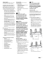
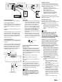
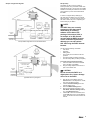
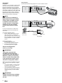
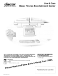
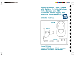
Installation Instructions
Dacor Kitchen Entertainment Center
save and read these instructions
CONVENTIONS USED IN THESE INSTRUCTIONS
WARNINGS:
Must be followed carefully to avoid personal injury or damage.
NOTES:
Contain helpful hints and tips to facilitate the installation.
IMPORTANT
1.
2.
3. 4. 5.
Before beginning installation, please thoroughly read and become familiar with these instructions.
Installation and service must be completed by a qualified installer or service agency.
Installer: Please leave these Installation Instructions with the owner.
Owner: Please keep these instructions for local electrical inspector’s use and for future reference.
Read the accompanying Use & Care Manual prior to operating this appliance.
TABLE OF CONTENTS
Installing the DKEC
Getting started
Verifying package contents
Tool checklist
Route the cables
Prepare the site
Connectivity template
Position the bracket
Mount the DKEC
Install the batteries
Power up
Internet connection information
Video mode
Registering a new DKEC
Part No. 65514 Rev. B
Page
Page
Page
Page
Page
Page
Page
Page
Page
Page
Page
Page
Page
2
2
2
2
2
3
3
3
4
4
4-6
7
7
INSIDE FRONT COVER
THIS PAGE IS BLANK INTENTIONALLY
Getting Started
The first question new DKEC owners need to
ask is,“Where should I install my DKEC?”
The installer and home owner should discuss
the question to come up with a mutually
satisfactory solution. The choice of where to
locate the DKEC is a very important one. The
DKEC is designed for the kitchen environment.
To get the maximum benefit from the product on
a daily basis, consider the following details:
•
Most kitchens have a “work triangle” as
defined by the sink, the refrigerator and the
stove. This is where people typically spend
most of their time while in the kitchen.
Consider how the unit will most easily be
viewed, taking into account that the display
can pivot 60 degrees to either side of
center.
•
How much light from sources such as
windows will fall directly on the screen?
Uncontrollable light flooding the screen
can make it difficult to view content on the
DKEC screen.
•
Don’t install the DKEC above a stove, a
coffee maker, sink, dishwasher vent or any
other location that will subject it to high
heat and/or humidity.
•
The installer will need to get the necessary
wiring to the unit. Careful consideration
needs to be given to how the installer plans
to run and conceal the wires. Consideration
should be given to suitable locations for the
junction boxes where wires will terminate
behind the unit.
Before beginning the installation of the DKEC
the installer should:
•
Read through all installation instructions.
•
Make sure all peripheral connections are
available at the installation location (TV
cable, electrical power, connections to
security locks, video monitor, phone line, or
Broadband).
•
Seek additional information from other
sections of this document including Internet
Connection Information and Video Mode
sections.
Verifying the Package Contents
•
•
•
•
•
•
•
•
•
•
•
•
•
•
•
DKEC unit
Use and Care Manual
Washable, wireless keyboard
Two (2) AA batteries for keyboard
Washable, wireless remote
Two (2) AAA batteries for remote
Two (2) Styli
AC Power Cord
Right Angle F connector.
PCMCIA Ethernet Card
Mounting Bracket
Mounting Template
Connectivity Template
Quick Start Guide
Remote and Keyboard Guide
Tool Checklist
The following tools may be necessary for
installing the DKEC:
•
Drill and drill bits
•
Standard and Phillips head screwdrivers
•
Small standard screwdriver
•
Wallboard saw or knife
•
Center punch or awl
•
RJ45/RJ11 crimping tool
•
RG6 - f connector - stripping/crimping tool
•
Masking tape
•
Tape measure
•
Pliers
•
Zip ties
Note:
Mounting screws are NOT
included with the DKEC. While
we recommend the use of six
5/16” T-nuts and screws, it is
impossible to predict the length
of screws needed for a particular
customer’s installation.
WARNING:
Installation of this device should
be performed by a professional.
Proper installation requires
ensuring that the supporting unit
can bear the weight of the device,
that all mountings are secure
and that electrical and telephone
wiring meets local building codes,
and that all mounting instructions
are followed. IMPROPER
INSTALLATION COULD LEAD TO
PROPERTY DAMAGE, SEVERE
PERSONAL INJURY OR DEATH.
Dacor disclaims any and all
liability for damages and/or
injury resulting from improper
installation.
Note:
If you are installing the DKEC
in a site that has structured
wiring, see Internet Connection
Information for more information.
Also see Connectivity Template
on page 3 for suggested
termination layout.
Prepare the Site
The two most common installation
configurations for the DKEC are shown below.
The minimum space required is also shown.
It is advisable that the DKEC installer consult
with the kitchen cabinet installer to ensure
that the site is properly prepared prior to the
installing of the DKEC.
Selecting a suitable site for installation:
•
Avoid areas where the DKEC would be
exposed to extreme heat or moisture.
•
Allow a full 11” of horizontal space (front to
back), accounting for backsplash and trim if
necessary.
•
The mounting surface must be flat and
level.
•
The cabinet material must be at least ½”
thick and able to support 30 lbs.
•
When installing the unit, allow sufficient
vertical space above the countertop to
accommodate screen in lowered position.
The minimum distance required is 13”.
3 3/4”
(97mm)
13”
(330mm)
23 5/8”
(600mm)
10 13/16”
(275mm)
Route the Cables
The following is the full list of cables that
may need to be run to the installation site.
Each installation site will require different
configurations depending on how the DKEC will
be used.
•
RG6 cabling with a coaxial cable connector
(F-style) for the cable TV service.
•
S-Video cable
•
Analog signal cable, left and right channel
with RCA connectors for audio input
or output (these are separate from the
connectors for the internal speakers).
•
RCA Composite video cable
•
AC power cables with a ground should
be routed to within 3 ¾” of the top of the
installation site to hide cables from view.
•
Telephone wire with the RJ11 connectors
for Dial-Up Internet access.
-or•
CAT 5 wire with an RJ45 connector for
Ethernet connection.
Shown in a Custom Built Nook
23 5/8”
(600mm)
13”
(330mm)
10 13/16”
(275mm)
Shown Under a Standard Flat Cabinet Surface
Connectivity Template
The Connectivity Template included with the
DKEC suggests how the unit could be wired
under ideal conditions. It enables the installer
to determine ahead of time where to place the
junction boxes and outlets.
Keep in mind, however, that the existing wall
contains structural studs. The location of these
studs will dictate what kind of junction boxes can
be used and where they can be placed. There
is no guarantee that the layout suggested by the
Connectivity Template will work “as is” for each
particular situation.
Place the template on the wall area behind the
location for the unit. It should be located such
that the center line of the template (see marking
on template) is aligned with the desired center
line of the DKEC unit. Note that the images on
the Connectivity Template include the outline of
the DKEC unit itself.
Position the Bracket
Position the Mounting Template in the desired
location.
•
If the bottom surface of the kitchen cabinet
(where the bracket is to be mounted) is
recessed from the bottom of the kitchen
cabinet frame, you will need to bring the
bracket and the cabinet into alignment.
This should be done using furring strips at
the locations of the mounting screws.
•
For reasons of aesthetics, also note
where the bottom of the DKEC unit itself
will be when the unit gets installed into
the bracket. In cases where the unit is
installed into a custom nook, the bottom
of the DKEC should align with the bottom
surfaces of the adjacent kitchen cabinets.
•
Using the template, make sure that the
bracket will be mounted such that the
vertical face of the DKEC unit will be flush
with or just slightly recessed back from the
vertical face of the cabinets.
•
Leave adequate clearance in the rear for
electrical/electronic connections.
Tape the Mounting Template in position, then
mark the locations of the 6 mounting holes. Use
an awl or nail to create a center mark in each
mounting hole. Remove the template.
Positioning the Connectivity Template
Recommended Products:
•
Two Siemon Home Recessed Wall plates,
From the Angled MaxTM Tool less line,
Part number MX-TFP-S-06-25
•
Five recessed RCA connectors for the
audio and video connections, Siemon
Home part number MX-RC-25
•
One F connector, for radio and television
reception, Siemon Home part number MXFA-25
•
One RJ45 connector for the Ethernet
connection, Siemon Home part number
MX5-F25
•
One RJ11 connectors for a Dial Up
connection, Siemon Home part number
MX3-F25
•
Grounded Clock hanger receptacle, Pass &
Seymour part number S3713 or S3833
Option B
The installer may need to take an approach that
is a variation on the approach shown on the
Connectivity Template. In some circumstances
it may be more desirable to use the following
product:
•
Leviton 80704W wall plate, fits to a single
gang receptacle and has a 1 -3/8 inch
diameter hole in the middle. (All terminal
cables can be run directly out of the hole in
the wall plate.)
“A”
“C”
Attaching the Unit to the Mounting Bracket
Before securing the unit, plug the cables into the
appropriate connectors as indicated on page 4.
Loosen the two screws on the bracket in order
to receive the two slotted tabs along the rear
edge of the unit. Slide the DKEC unit into the
bracket. The tabs should fully engage the pins
(“B”, as shown above).
Using a screwdriver, tighten the screws on the
mounting bracket, alternating between the two
screws until the tabs are secure (“C”, as shown
above).
When installation is complete, the face of the
unit should be flush with, or slightly recessed
from the face of the cabinets.
The template can be held in place with masking
tape. Make sure that the template is right side
up on the wall (look for the Top arrow).
Option A
Based on the Connectivity Template the
following items are recommended for the actual
wiring of an DKEC unit:
“B”
Positioning the Mounting Template
Remove the mounting bracket from the top of
the DKEC by loosening the two screws at the
back of the unit using a screwdriver.
We recommend installing the mounting bracket
with six 5/16” T-nuts and screws. Seat the
screws firmly against the bracket, but do not
overtighten.
Completed Installation
Installing the Mounting Bracket
Mount the DKEC
Install the DKEC onto the mounting bracket
taking care to align the guide rails on the
bracket with the rails on top of the DKEC (“A”,
as shown in “Attaching the Unit to the Mounting
Bracket”). Slide the unit about half way back on
the rails.
Detailed Instructions
The DKEC supports three types of Internet
connectivity using a PCMCIA network interface
card (NIC). Depending upon which type of card
is used, you can connect using:
•
Wired (Ethernet) Broadband. Your
broadband service may be provided over
DSL or cable modem.
•
Wireless (802.11b) Broadband.
•
Dial-Up Internet Access. The dial-up
Internet services must not require the
installation of additional software.
Rear Panel Connections
FM Antenna
Broadband
Power
Cable
Rear Panel Connections
Install the Batteries
Prior to turning on the unit, do the following:
Install Keyboard Batteries:
Using a Phillips screwdriver, remove the 2 large
screws in the battery cover on the backside
of the keyboard. Then remove the cover and
gasket.
Install two (2) AA batteries (supplied) into the
keyboard.
Reinstall the gasket, battery cover, and screws.
Install the screws so that the battery cover is
firmly seated, but do not over tighten. Make
sure that the small rubber washer associated
with each screw is properly installed when
reattaching the cover.
Power Up
The DKEC is initially powered on in two steps:
1. Locate the red rocker switch on the back
of the unit near the AC power connection.
Push this switch to the “on” position to
power on the device. (This switch can
also act as a “reset” by flipping it “off” then
back to “on”, but it is intended to always
remain in the “on” position unless a reset
is necessary.) The unit will boot up in
approximately one minute. A steady red
light indicates that the device is on and in a
“sleep” state.
2. To bring the unit out of “sleep” state, use
either the On/Off button on the keyboard
or remote or on the front panel of the unit.
The unit can be returned to “sleep” state by
pushing one of these buttons.
Install Remote Batteries:
Using a Phillips screwdriver, remove the small
screw in the battery cover on the backside of
the remote.
Install two (2) AAA batteries (supplied) into the
remote. Install the screws so that the battery
cover is firmly seated, but do not over tighten.
Make sure that the small rubber washer
associated with the cover screw is properly
installed when reattaching the cover.
Secured Screw
Battery Cover
Rubber Gasket
Battery Cover
Secured Screw
On/Off Button
On/Off Button
Internet Connection Information
Making it Simple
The DKEC is engineered to take advantage of
a Broadband connection and comes with an
Ethernet Networking card which can be inserted
into the PCMCIA slot on the rear of the device.
If your home has a Broadband service installed
(cable, satellite or DSL),
and
The Broadband service supports DHCP,
and
The modem is installed and configured,
and
The router (which is optional) is installed and
configured,
then
Simply insert the included PCMCIA card, and
plug the card into the modem (or router, if
used) using an RJ45 network cable. Power up
the DKEC and push the Internet button on the
remote or keyboard. The DKEC will connect to
your Broadband service using DHCP.
Note:
Installing the Batteries
No additional software needs to
be loaded onto the DKEC for it to
work with a Broadband Internet
connection.
The following instructions cover three basic
methods of access - Wired Broadband, Wireless
Broadband or Dial-Up.
Wired Broadband Setup
If Internet access is provided through a
Broadband service using the included Ethernet
card, the instructions cover the following
scenarios:
•
Case #1 - An existing network is in place
and an Internet connection is being shared
among devices on the network, or;
•
Case #2 - The local network is not yet in
place.
Note:
The Ethernet card can only be
used for Internet browsing or
access. File transfer, file sharing,
print sharing, and other LAN/WAN
functions are not supported.
Broadband Case # 1: Existing Network
The first configuration option is connecting your
DKEC to an existing network with a shared
Broadband connection. These instructions
assume you have a router/switch (with an
available port) in place on your network that
supports multiple internal network IP addresses.
A. Route and Connect Cables
Make sure that the router is connected to
the Ethernet card inserted in the DKEC. If
this is not already done, route a standard
Ethernet (category 5) cable with RJ45
plugs between your router and DKEC.
Take care to connect the DKEC to a free
Ethernet jack in the back of the router
and not to the WAN port. The WAN port
is reserved for the Ethernet cable coming
from the modem.
B. Configure Broadband Settings
To configure your Broadband Connection
Settings:
1. Press the Internet button on the
keyboard or remote, then press the
Options button.
2. Choose Connection Settings from the
Internet Options menu.
3. Select the Broadband Settings button.
The DKEC will display the Broadband
Settings screen.
4. If your router/switch (or the modem/
router/switch combination) supports
DHCP, select the Use DHCP server
checkbox by pushing the Go or Enter
buttons on the remote or keyboard,
or tapping the checkbox on the touch
screen.
If DHCP is not supported, you will
5.
6.
need detailed information from your
ISP so that you can complete the
required fields. This include the IP
address, Subnet Mask Gateway
Router and the DNS Primary and
Secondary numbers that must be
entered in the appropriate fields.
Choose OK to save the information,
choose OK again.
Choose the Refresh Connection
button, then choose OK to exit the
Options menu. The DKEC should now
have be connected to the Internet.
Broadband Case #2: No Existing Network
Assumptions
These instructions assume the following existing
conditions:
•
The site of the installation has a Broadband
(cable, DSL or satellite) Internet connection
installed. If this is not the case, please
call your Broadband provider to have this
service installed.
•
The Broadband services provided to
the home support DHCP (Dynamic Host
Configuration Protocol). If you are not sure,
contact the Broadband service provider. If
they do not support DHCP, ask your ISP
to provide you with a static IP address and
two DNS numbers.
•
It is assumed that the Broadband provider
has supplied the owner with a cable or DSL
modem. If the modem was not connected
to the Broadband termination box, contact
the provider to get the instructions for doing
this.
•
The modem the Broadband service
provider has supplied supports DHCP.
If you are not sure contact the service
provider to verify that this modem will
support DHCP. If it does not, you will need
to manually configure the modem (see C.
Modem Configuration ).
•
The router/switch being used (or the
modem/router combination) will support
DHCP. If a router needs to be purchased,
DKEC, LLC recommends the following:
Linksys Router, Instant Broadband
Series, Ethernet Cable/DSL Router model
#BEFSR81.
You may need to use a router for one of two
reasons. Either you want to connect to your
Broadband connection with more then one
device (e.g. a computer and a DKEC), or you
are using a service provider that requires
authentication information to connect to their
service. If one of the above does apply, you will
need to place a router or switch between the
modem and the DKEC.
B. Modem Connection
Once you have verified that there is
a Broadband connection coming into
your location, you may need to connect
the provided equipment (most likely a
cable modem or DSL router provided by
the Broadband ISP) to the Broadband
connection. Many times the Broadband line
is installed to the location’s demarcation or
termination box. You will need to find this
box to determine how the location is wired.
This will give you the ability to connect the
modem/router to the Broadband line as
well as to the premise’s wiring.
C. Modem Configuration
Note:
This is typically done by the
service provider.
Once you have the modem connected to
a Broadband connection, you may have to
configure it. Does your Broadband modem
need configuring?
Yes:You will most likely not be able to
configure a Broadband modem with
a DKEC. Many modems have to be
configured by connecting the modem
to a PC and entering the information
such as IP address or user name/
work group/passwords. You will need
to configure it with a PC or contact the
provider for assistance.
No: Go to step D.
D. Router Configuration
If you are not using a router, simply make
sure that the Ethernet cable from the
modem is plugged into the Ethernet card in
the back of the DKEC.
If you are using a router, plug the cable
from your modem into your router’s WAN
port.
Next, run an Ethernet cable from the
Ethernet card in the DKEC to a port in
the router. Once you have done this, you
can refer to the setup guide your router
manufacturer provided regarding the details
of router configuration.
Keep in mind that if your service
provider supports DHCP, follow the
router manufacturer’s directions that are
applicable for this situation.
Similarly, if your service provider does
not support DHCP, follow the router
manufacturer’s directions that are
applicable in this situation.
E.
Broadband Settings
Follow the same directions described in
“B. Configure Broadband Settings” on
page 4.
A. Is There a Broadband connection?
Yes:Go to step B.
No: Call Broadband provider to install.
Wireless Broadband Setup
There are two ways to connect the DKEC to
your wireless network:
•
Using a wireless bridge connected to the
Ethernet card, which is essentially an
Ethernet connection; or,
•
Using an approved wireless PCMCIA card.
Using a wireless bridge
I1. nsert the included networking card into the
PCMCIA slot on the back of the DKEC.
2. Connect the wireless bridge to your home
PC and configure it following the directions
provided by the manufacturer of the bridge.
3. When the wireless bridge is properly
configured for your wireless network,
disconnect it from your home PC.
4. Insert one end of an Ethernet cable into the
bridge, and one end into the Ethernet jack
on the PCMCIA card.
In most cases, no further connection settings
are required. If no connection is established
when you first go to Internet Mode, see
“B. Configure Broadband Settings” on page 4 for
more information.
Using a wireless PCMCIA card
Because the DKEC uses the Windows CE .NET
platform, we cannot ensure the compatibility
of all wireless network cards. Please contact
customer support for a current list of supported
wireless PCMCIA networking cards.
The first time you go to Internet Mode, you will
need to enter any configuration settings required
by your wireless network. This may include
a WEP (Wired Equivalent Privacy) key and
other security settings. This may also include
additional IP information if you use a Static IP
address.
To connect using a wireless PCMCIA card
1. Insert a wireless networking card into the
PCMCIA slot on the back of the DKEC.
2. After turning on the DKEC, press the
Internet button on the keyboard or remote,
then press the Options button.
3. Choose Connection Settings from the
Internet Options menu.
4. Select the Wireless Settings button.
5. Select your home network.
6. If your network requires a WEP key, select
the Security button, then:
a. Select the appropriate security
options.
b. Enter the WEP key.
c. Choose OK.
7. If you use a static IP address, select the IP
button, then:
a. Clear the Use DHCP (Auto)
checkbox.
b. Enter static IP address, subnet mask,
gateway router and DNS servers.
c. Choose OK.
8. Choose the Connect button.
Some networks are set up to allow only specific
devices to connect based on the device’s MAC
(Media Access Control) address. You can
quickly find the MAC (Media Access Control)
address (also known as the physical address) of
your wireless card.
To find a card’s MAC address
1. From the Internet Options menu, select
Connection Settings.
2. Select the Wireless Settings button.
3. Select the IP button.
The MAC Address of the wireless card is
displayed. Write it down so you can enter it
when configuring your router for the DKEC.
Sample Configuration Diagrams
Dial-Up Setup
The DKEC can also connect to a dial-up
Internet provider, using a PCMCIA modem card
equipped with an RJ-11 phone jack. The installer
should run a twisted pair of wire from the master
phone panel to a junction box located behind
the DKEC.
Cable TV
Printer
Modem
Note:
Home
Office PC
Router
(could be wireless)
Incoming
Cable
Incoming
Phone Wire
Audio Station
Printer
CD Player
Example of DKEC Configuration as Part of Home-Based Ethernet
•
•
Game Console
Cable TV
Combined into a single
unit in some cases
Modem
Router
(could be wireless)
The DKEC does not currently
support any ISPs that require
downloading or installing
software. At the time of the
printing of this manual, AOL is
an example of an ISP that will
not work with the DKEC because
of their download requirements,
although you can still retrieve
AOL mail using the DKEC Internet
browser.
You
•
•
•
•
Printer
Incoming
Cable
In order to configure Dial-Up Settings you
will need some information from your Internet
Service Provider. If you don’t have an ISP, you
will need to obtain one prior to completing the
Internet setup of your DKEC.
Video Camera
(via “video in”)
will need the following information:
User name
Password
Dialing Prefix
The access phone number the ISP has
provided
The Primary DNS (not always required)
The Secondary DNS (not always required)
To connect using a Dial-Up connection
1. Insert the modem card into the PCMCIA
slot on the back of the DKEC.
2. Plug the analog telephone line into RJ-11
jack on the modem card.
CAUTION:
Incoming
Phone Wire
Typical DKEC Accessory Configuration
Do not connect the DKEC to a
digital phone line. Severe damage
can occur to the DKEC.
3.
4.
5.
6.
7.
After turning on the DKEC, press the
Internet button on the keyboard or remote,
then press the Options button.
Choose Connection Settings from the
Internet Options menu.
Select the Modem Settings button.
Enter the appropriate information in the
User Name, Password, Dialing Prefix (if
any), and ISP Phone # fields.
Choose OK to save the information, then
choose OK twice more to exit the Options
menu. You should now have access to the
Internet.
Video Mode
Introduction
The DKEC can be connected to a video camera
which you can use to monitor another part of
the house. For example, you can monitor the
activity in a child’s room or see who is at the
front door. You can also use Video Mode to view
video tapes on a VCR or play video games on a
game system. Additionally, you may wish to take
advantage of the higher quality of Satellite or
Digital Cable by using the S-video connection,
which can also be viewed in Video Mode.
Wiring Diagrams
We have provided basic wiring diagrams for a wired or wireless camera.
Back of DKEC
Video Camera
Note:
If you connect your Satellite or
Digital Cable service to the DKEC
using S-Video, the DKEC remote
or keyboard cannot be used to
change channels in Video Mode.
Continue to use your existing
remote control with the set-top
box.
Back of DKEC
To 120VAC
Wireless Base Unit
Example Model:
X10.com, VR31A
If you’ve connected both an S-Video and a
composite signal, both are accessible from
Video mode.
To connect an S-Video source
•
Plug an S-Video cable from the camera,
VCR, game machine or satellite/cable
receiver into the S-Video connection on the
back of the DKEC. To the right are samples
of wiring diagrams for a wired or wireless
camera.
To view video sources
1. Press the Video mode button.
The composite signal (if any) appears.
2. Press the Video mode button again.
The S-Video signal (if any) appears.
Support and Registration
Registering a New DKEC
IMPORTANT:
This section assumes that
the DKEC unit has been fully
configured for either Broadband,
Wireless or Dial-Up connectivity.
If this is not the case, please refer
to the appropriate section in this
manual for configuration details.
Before going online with the DKEC for the first
time, you are given the opportunity to register
the unit.
•
If you are the installer, you should choose
the Register Later button, and allow the
owner to complete registration.
•
If you are the owner, choose the Register
Now button to ensure that the warranty is
activated and that you receive software
updates.
IMPORTANT:
In order to receive future software
updates, the owner must register
the unit.
Wireless Camera
Example Model:
x10.com, XC10A
Addressable Power Supply
Example Model:
x10.com, XM10A
To 120VAC
Wiring Diagrams
NOTES:
NOTES:
NOTES:
Web Site:
Phone:
www.dacor.com
(800) 793-0093