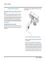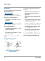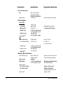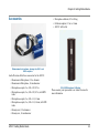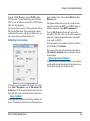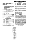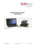
1
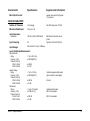
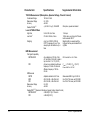
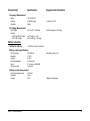
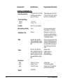
APx511 hearing instrument analyzer Installation Instructions, Specifications, and Getting Started Guide model APx511 Requires APx500 v 3.3 or later. Copyright © 2011–2013 Audio Precision, Inc. All rights reserved. Printed in the United States of America. No part of this manual may be reproduced or transmitted in any form or by any means, electronic or mechanical, including photocopying, recording, or by any information storage and retrieval system, without permission in writing from the publisher. Audio Precision, AP, and APx are trademarks of Audio Precision, Inc. Windows™ is a trademark of Microsoft Corporation. Dolby and the double-D symbol are trademarks of Dolby Laboratories, Inc. DTS is a trademark of DTS, Inc. Audio Precision 5750 SW Arctic Drive Beaverton, Oregon 97005 503-627-0832 800-231-7350 ap.com pn 8211.0308 rev 000 XIII0514131702 Documentation and Support This booklet contains safety information, installation instructions and full specifications for the Audio Precision APx511 hearing instrument analyzer. A Getting Started chapter shows you basic interconnection diagrams and an introduction to controlling the APx511 with your automation software. ap.com Visit the Audio Precision Web site at ap.com for APx support information. APx resources are available at ap.com/downloads/apx. You can also contact our Technical Support staff at [email protected], or by telephoning 503-627-0832 extension 4, or 800-231-7350 extension 4 (toll free in the U.S.A.). Safety Safety Information Do NOT service or repair this equipment unless properly qualified. Servicing should be performed only by a qualified technician or an authorized Audio Precision distributor. Do NOT defeat the safety ground connection. This equipment is designed to operate only with an approved threeconductor power cord and safety grounding. Loss of the protective grounding connection can result in electrical shock hazard from the accessible conductive surfaces of this equipment. Do NOT exceed mains voltage ratings. This equipment is designed to operate only from a 50–60 Hz ac mains power source at 100–240 Vac nominal voltage. The mains supply voltage is not to exceed ±10 % of nominal (90–264 Vac). APx511 Safety For continued fire hazard protection, fuses should be replaced ONLY with the exact value and type indicated on the rear panel of the instrument and discussed on page 10 of this booklet. The International Electrotechnical Commission (IEC 1010-1) requires that measuring circuit terminals used for voltage or current measurement be marked to indicate their Measurement Category. The Measurement Category is based on the amplitude of transient or impulse voltage that can be expected from the AC power distribution network. This product is classified as Measurement Category I, abbreviated “CAT I”. This product should not be used within Categories II, III, or IV. The APx511 measurement terminals are intended to be used for the measurement of audio signals only. Do NOT substitute parts or make any modifications without the written approval of Audio Precision. Doing so may 1 Chapter 1: Safety create safety hazards. Using this product in a manner not specified by Audio Precision can result in a safety hazard. This product is for indoor use—Installation Category II, Measurement Category I, pollution degree 2. To clean the enclosure of this product, use a soft cloth or brush to remove accumulated dust. A mild detergent may be used to remove remaining dirt or stains. Do not use strong or abrasive cleaners. Wipe all surfaces with a damp cloth. This unit is supplied with four feet on the bottom surface and four feet on the right side surface. The unit should only be operated while resting on the bottom surface feet. The feet on the right side are provided for convenience and stability when transporting the unit. DO NOT operate the unit while it is sitting on the side feet. Safety Symbols The following symbols may be marked on the panels or covers of equipment or modules, and are used in this manual: WARNING!—This symbol alerts you to a potentially hazardous condition, such as the presence of dangerous voltage that could pose a risk of electrical shock. Refer to the accompanying Warning Label or Tag, and exercise extreme caution. 2 ATTENTION!—This symbol alerts you to important operating considerations or a potential operating condition that could damage equipment. If you see this marked on equipment, refer to the Operator’s Manual or User’s Manual for precautionary instructions. FUNCTIONAL EARTH TERMINAL—A terminal marked with this symbol is electrically connected to a reference point of a measuring circuit or output and is intended to be earthed for any functional purpose other than safety. PROTECTIVE EARTH TERMINAL—A terminal marked with this symbol is bonded to conductive parts of the instrument and is intended to be connected to an external protective earthing system. Disclaimer Audio Precision cautions against using their products in a manner not specified by the manufacturer. To do otherwise may void any warranties, damage equipment, or pose a safety risk to personnel. APx511 Safety Chapter 1: Safety APx511 Safety 3 4 APx511 Installation Installation Software The APx511 hearing instrument analyzer system uses the award-winning APx500 measurement software, whether using the GUI in the foreground, or controlling APx500 in the background using the API. This is the same software used in the APx525and APx585 analyzer families. PC system requirements The APx500 measurement software requires a personal computer (PC) with the following features and capabilities: • Operating system: Microsoft Windows 8, Windows 7, Windows Vista, or Windows XP Professional (Service Pack 2 or later). • A multi-core processor (at least dual-core) running at a clock speed of at least 2 GHz. Most current processors from Intel and AMD meet these requirements. APx511 Installation Note: the Intel Atom processor does not meet our minimum specification. • • • • At least 2 GB of RAM. At least 300 MB of free hard disk space. A CD-ROM optical disc drive. A USB 2.0 port; two are required for optional switcher use. • A color monitor and a video card with at least VGA capabilities. Video resolution of 1024 x 768 or greater is recommended. System performance is sensitive to processor speed; faster processors will yield faster results. 5 Chapter 2: Installation APx500 is data intensive and it is recommended that other data-intensive applications not be run concurrently. This includes Audio Precision’s AP2700, APWIN or ATS. Installation To install the measurement software, insert the APx500 CDROM into the optical drive on the PC and follow the instructions in the installation dialog. NOTE: You must have local administrator rights to install APx500 software. Go to User Accounts in the Windows Control Panel, or check with your network administrator. Running the software without instrument hardware attached NOTE: You must have standard user rights or administrator rights to operate APx500 software. Guest users are not supported. You can launch the APx500 software without instrument hardware attached. When no hardware is detected, APx500 will present you with the following dialog box: Select “Demo Mode.” APx500 will run in demo mode, which allows you to explore the user interface but does not 6 enable any measurement functions. Input data shown in Demo Mode is false data, generated for display only. At first launch, Demo Mode runs simulating attachment to an APx585. To run Demo Mode simulating anther instrument, select that option from the Instrument Type menu. The APx511 instrument is not an available option in Demo Mode. Running the software with instrument hardware attached NOTE: You must have standard user rights or administrator rights to operate APx500 software. Guest users are not supported. Connecting the instrument to your PC Before connecting your APx511 instrument to your PC, install the APx500 measurement software as described above. Connecting the instrument prior to software installation may cause Windows to select an incorrect USB driver for the instrument. USB driver selection The measurement software communicates with the APx511 using a USB 2.0 interconnection. Once the software is successfully installed, connect one end of the USB cable to a USB 2.0 port on the PC, and the other end to the PC INTERFACE port on the rear of the APx515. We strongly recommend that you use the USB cable included with your instrument (AP part number CAB-APSI). We have tested other USB cables that perform poorly. Note: Some PCs have optional USB ports on the front of the PC, or on extension brackets on the rear. In many cases these convenience ports have compromised performance due to the extra cable length within the PC. We recommend using APx511 Installation Chapter 2: Installation USB ports directly connected to the PC motherboard, typically at the rear of the PC. Connect the APx511 mains power cord to the instrument and to a source of ac mains power. See Setting up the hardware below for more information about mains connections. Turn the instrument on by rocking the mains power switch up to ON ( | ). The mains power switch is located in the power entry module on the rear of the APx511. Windows will detect the presence of the APx511 on the USB port and will open the Hardware Update Wizard to search for the correct software driver. Select “Install the software automatically.” Windows will find the Audio Precision driver software installed with APx500 and connect to the APx511. Launch APx500 by double-clicking on the installed shortcut. With the APx511 connected, you may be asked to update the instrument firmware during the first launch of the measurement software. APx500 will start, and in a short time you will be presented with the opening screen. Refer to the APx500 User’s Manual for more information about making measurements. The instrument has been configured at the factory for the expected voltage at its intended destination, as ordered. The voltage setting and fusing arrangement will normally be correct unless the instrument has been transported into another area. The power entry module has a strip of indicator tape showing its mains voltage setting. This tape must be removed before use. You MUST be sure that the APx511 instrument mains power configuration is correct for the electrical mains power supplied in your area. If you are not sure, do not plug the instrument into the mains power. Follow the instructions below to check or change the instrument mains supply voltage selection. The mains power supply is applied to your APx511 instrument through the power entry module located on the rear panel. Before connecting the power cord, confirm that the input voltage selection and fusing arrangement in the power entry module are correct for your mains power supply. The APx500 User’s Manual is available as a PDF on the APx500 Application Disc and online at ap.com; a hard-copy version can be ordered from Audio Precision or your local distributor. Setting up the hardware Connecting your instrument to the electrical mains supply The APx511 instrument must be connected to a 50–60 Hz alternating current (ac) electrical mains supply, maximum voltage 250 Vrms. APx511 Installation Figure 2. Detail of power entry module on APx511 instrument rear panel. 7 Chapter 2: Installation The mains power switch is to the left. To open the power entry module, refer to Figure 3 and proceed as follows: Checking the mains supply voltage configuration The white plastic voltage indicator pin protrudes through one of the four labeled holes in the module cover to indicate the selected input voltage. Figure 2 shows the pin in the second position, indicating 120 V. Check to see that the indicated voltage matches your mains supply voltage. If it does not, change the mains supply voltage configuration as described below. Opening the power entry module Unplug the power cord from the instrument before changing fuses or performing any other operations described in this section. Figure 3. Power entry module door and fuse block. • Remove the mains power supply cord from the power cord connector. • Locate the slot in the module cover door hinge. The hinge is a the left side of the cover door, and the slot in the hinge is visible in the power cord connector cavity. Insert a small screwdriver or similar tool in the slot and pry the cover door hinge outward. The cover door will snap out, and then can be pivoted on its hinge for access to the fuse block assembly and voltage selector card. 8 APx511 Installation Chapter 2: Installation Changing the Mains Supply Voltage Configuration • Open the Power Entry Module as described above. • The voltage selector card is a small circuit board fitted with a white plastic indicator pin, installed in a housing on the right side of the Power Entry Module as shown in Figure 4. Pull the voltage selector card straight out of the housing, using narrow pliers to grab the card. Do not use the indicator pin as a handle. connector. The card edge indicating the desired voltage should enter the housing first. • Confirm that the correct fuse or fuse combination is installed for the intended input voltage (refer to the fuse ratings marked on the instrument rear panel). If necessary, change the fuse type as described in the following section. 100V 90° 120V 90° 230V 90° 240V Figure 5. Voltage card selector orientation. Figure 4. Changing the mains power supply voltage. • Close the module the cover door and verify that the indicator pin shows the desired voltage. • Once you have verified that the line voltage selection is correct, connect the power cord from a mains power outlet to the power cord connector on the instrument rear panel. • Orient the selector card so that the desired input voltage is readable at the bottom, shown in Figure 5. Then move the indicator pin to point UP, opposite the indicated voltage. Seat the pin assembly in the notch on the board edge. • Insert the voltage selector card into the housing with the printed side of the card facing toward the mains power APx511 Installation 9 Chapter 2: Installation Fuse information The power entry module accommodates two fusing arrangements, as illustrated in Figure 6. 100/120 VAC operation The 100/120 VAC fusing arrangement uses a single type 3AG (0.25" x 1.25") slo-blo fuse. Audio Precision recommends only the following replacement fuse: • 1 each Littelfuse 313 Series, 800 mA 3AG 250 V sloblo glass fuse. 230/240 VAC operation The 230/240 VAC fusing arrangement uses two 5 x 20 mm IEC-approved type T fuses. Audio Precision recommends only the following replacement fuses: • 2 each Littelfuse 213 Series, 400 mA 250 V 5 x 20 mm Time Lag (slo-blo) glass fuses or • 2 each Littelfuse 218 Series, 400 mA 250 V 5 x 20 mm Time Lag (slo-blo) glass fuses. Refer to the label on the instrument rear panel for fuse current ratings. To replace a fuse or change the fusing arrangement, proceed as follows: • Remove the mains power cord from the power cord connector and open the Power Entry Module as described above. • Using narrow pliers, pull the fuse assembly out of the housing. • Change or add the correct fuses as necessary, referring to Figure 6. Refer to the instrument rear panel for the correct fuse electrical current rating. • Insert the fuse assembly in the housing, with the side of the assembly that carries the fuse(s) for your desired fusing arrangement facing into the housing. Press the fuse assembly firmly into the housing. • Confirm that the line voltage selection is correct for your mains voltage and your fusing arrangement. Once you have verified that the line voltage selection is correct, connect the power cord from a mains power outlet to the power cord connector on the instrument rear panel. Changing the fusing arrangement Figure 6. Fuse block orientation for 100/120 VAC and 230/240 VAC operation. 10 APx511 Installation Specifications APx511 hearing instrument analyzer with APx500 v3.3 or higher measurement software March 2013 NP0020.00020 r000 Characteristic Specifications Supplemental Information Number of Channels 2, independent amplitude control Speaker and telecoil output on DB-15 on rear panel Waveforms Sine, continuously swept-sine, noise, IMD test signals, multitone, wave file playback ANALOG GENERATOR Sine Characteristics Frequency Range (Fs) Frequency Accuracy Amplitude Range (Speaker) Amplitude Range (Telecoil) Amplitude Accuracy, 1 kHz Speaker Output Amplitude Accuracy, 1 kHz Telecoil Output Flatness (1 kHz ref) 100 Hz to 10 kHz 10 kHz to 20 kHz Residual THD+N1,2 Fs = 100 Hz–20 kHz Non-Harmonic Content APx511 Specifications 100 Hz to 20 kHz ±(0.0003% + 100 μHz) 0 to 5.7 V rms [16.1 Vpp] into 8 0 to 110 mA rms into 4 ±0.05 dB [±0.60 %] Setting resolution is typically 45 µHz 4 W into 8 ±0.1 dB [±1.0 %] ±0.05 dB ±0.1 dB (–80 dB + 1.4 µV), 20 kHz BW Typically ≤0.005% THD+N Typically ≤110 dB when Fs ≤20 kHz 11 Characteristic Specifications Supplemental Information White (<5 Hz to 0.45*SR), Pink (<10 Hz to 0.45*SR), IEC 60268-1 or BS EN 50332-1 0 to 16.12 Vpp Amplitude calibration is approximate Noise Characteristics Shape Amplitude Range IMD Test Signals SMPTE & MOD LF Tone Range HF Tone Range Mix Ratio (LF:HF) Amplitude Range Amplitude Accuracy Residual IMD1,2,3 100 Hz to 1 kHz 2 kHz to 10 kHz 10:1, 4:1 or 1:1 0 to 16.12 V pp, speaker output; 0 to 310 mA pp, telecoil output. ±0.06 dB [±0.70%] ≤0.01% [–80 dB], 4:1 mix ratio Tone Pair Mean Range Tone Pair Difference Range 2.5 kHz to 10 kHz 100 Hz to 2.0 kHz Amplitude Range 0 to 16.12 V pp, speaker output; 0 to 310 mA pp, telecoil output. ±0.06 dB [±0.70%] 0.01% [–80 dB] DFD Amplitude Accuracy Residual IMD1,2,3 HF tone must be 6 • LF tone. 4:1 maximum with SMPTE signal. Fmean = (F1 + F2)/2. Fdiff = |F2 - F1| Fmean must be ≥6 • Fdiff Multitone, Wave File Playback Sample Rate Range (SR) Maximum File Size Amplitude Range Flatness (1 kHz ref) SR = 175 kS/s to 192 kS/sec SR = 8 kS/s to 108 kS/s Spurious Content 12 8 kS/s to 108 kS/s, and 175 kS/s to 192 kS/s 32 MSample. 0 to 16.12 V pp, speaker output; 0 to 310 mA pp, telecoil output. Operation from 109 kS/s to 175 kS/s is possible, but with degraded flatness .Wav file must peak at digital full scale to obtain selected amplitude Typically <0.012 dB to 20 kHz Typically <0.04 dB to 20 kHz; max frequency limited to ≈0.45 • SR Typically <–100 dB APx511 Specifications Characteristic Specifications Supplemental Information speaker output current limit typically 1.5 A peak min Max Output Current ANALOG ANALYZER Number of Channels 1 auto-ranging. Maximum Rated Input 48 V pp, 24 V dc Max ADC sample rate = 192 kS/s Input Impedance Unbalanced 100 k || 230 pF to BNC shield Input Coupling AC Input Ranges 250 mV rms to 80 V rms, 10 dB steps BNC shield to instrument chassis ground. Typically <0.5 dB roll-off at 20 Hz Level (Amplitude) Measurement Microphone Input Range Accuracy (1 kHz) Flatness (1 kHz ref) 100 Hz to 10 kHz 10 kHz to 20 kHz Speaker Voltage Range Accuracy (1 kHz) Flatness (1 kHz ref) 100 Hz to 10 kHz 10 kHz to 20 kHz Telecoil Input Range Accuracy (1 kHz) Flatness (1 kHz ref) 10 Hz to 10 kHz 10 kHz to 20 kHz APx511 Specifications < 1 µV to 16.9 Vrms ±0.05 dB [±0.60 %] ±0.05 dB ±0.1 dB < 1 µV to 5.7 Vrms ±0.05 dB [±0.60 %] Limited by speaker amplifier output Open circuit with no load applied ±0.05 dB ±0.1 dB 8 load < 1 µA to 110 mA rms ±0.1 dB [±1.0 %] Limited by telecoil output With 1 load applied ±0.05 dB ±0.1 dB With 1 load applied 13 Characteristic Specifications Supplemental Information THD+N Measurement (Microphone, Speaker Voltage, Telecoil Current) Fundamental Range Measurement Range Accuracy Residual THD+N1,2 100 Hz to 20 kHz 0 to 100% ±0.5 dB (–80 dB + 1.4 µV), 20 kHz BW Microphone, speaker and telecoil Level & THD+N Filters High-Pass Low-Pass4 5 Hz to 500 Hz, or None 2.7 kHz to 90 kHz, or None Weighting A-wt, C-wt, CCIR-1k, CCIR-2k, CCITT, C-message, 50 μs or 75 μs de-emph (with and without A-wt), or None 1 Hz steps 100 Hz steps; very sharp roll-off characteristic exceeds AES-17 Weighting filter is cascaded with the high-pass and low-pass bandwidth limiting filters IMD Measurement Test Signal Compatibility SMPTE & MOD DFD Any combination of 100 Hz–1 kHz (LF) and 2 kHz–10 kHz (HF), mixed in any ratio from 1:1 to 10:1 (LF:HF) Any two-tone combination with mean frequency of 2.5 kHz–10 kHz and a difference frequency of 100 Hz– 2.0 kHz HF tone must be 6 • LF tone. Fmean = (F1+F2)/2, Fdiff = |F2–F1|. Fmean must be 6 • Fdiff IMD Measured SMPTE Amplitude modulation of HF tone. Measurement BW is typ. 40–500 Hz. MOD d2, d3, d2+d3, or d2+d3+d4+d5 Use “d2+d3” for meas. per IEC 60268 DFD d2, d3, d2+d3, or d2+d3+d4+d5 Use “d2+d3” for meas. per IEC 60268 Measurement Range 0 to 20% Accuracy ±0.5 dB Residual IMD1,2,3 (Speaker to Microphone, Speaker Voltage, Telecoil Current) SMPTE & MOD ≤–80 dB [0.01 %], 4:1 mix ratio DFD ≤–80 dB [0.010 %] 14 APx511 Specifications Characteristic Specifications Supplemental Information 100 Hz to 20 kHz ±0.0003% [3 ppm] 6 digits Vin must be 5 mV. 0.25 V to 80 V, 10 dB steps ±24 Vdc maximum in 25 V range Frequency Measurement Range Accuracy Resolution DC Voltage Measurement Input Ranges Accuracy 250 mV and 800 mV ranges 2.5 V to 80 V ranges ±(0.7% reading + 1 mV) ±(0.7% reading + 0.1% range) Battery simulator Number of outputs 1 on DB15 connector on rear panel Battery output specifications DC output range Resolution Accuracy DC output impedance Noise DC output current 0 to 2.048 Vdc ≤ 15 mV ±15mV 4.3 ohms ± 5% ≤ 1 mV pp over 10kHz BW 30 mA dc Resolution typically 1 mV Battery current measurement Current measurement range Resolution Accuracy APx511 Specifications 0 to 30 mA 10 µA ±5 % Release 3.3 and greater. 15 Characteristic Specifications Supplemental Information GENERAL/ENVIRONMENTAL Power Requirements 100, 120, 230 or 240 Vac, 50–60 Hz, with safety ground via approved power cord, 75 VA max. Typical operating range is 90–110 Vac (100V), 108–132 Vac (120V), 198–242 Vac (230V), or 216–264 Vac (240V). Temperature Range Operating Storage Humidity 0° C to +45° C –40° C to +75° C 90% to +40° C (non-condensing) Max Operating Altitude 3,000 m Stabilization Time 20 minutes EMC IEC 61326-1:2005 / EN 613261:2006. Complies with EC Council Directives 2004/108/EC and 93/68/ EEC. Safety IEC 61010-1:2001 / EN 610101:2001, CAN/CSA-C22.2 No. 610101-04, and UL Std No. 61010-1 (2nd Edition). Complies with EC Council Directives 2006/95/EC and 93/68/ EEC. Derate max operating temperature above 2,000m by 1° C per 200m Allow at least 60 minutes if unit has been stored in a significantly different environment prior to turn on, or if unit is to be calibrated or adjusted Emission and immunity levels are influenced by the shielding performance of interface and signal cables attached to the instrument. EMC compliance was demonstrated using Audio Precision cables Equipment Class I, Installation Category II, Pollution Degree 2, Measurement Category I Dimensions Width Height Depth Weight 16 374.5 mm (14.75 inches) 79 mm (3.11 inches) 413 mm (16.27 inches) Including handle 2U rack mount tray available. Increase by ≈8mm [0.3 inches] if rear panel option keys are installed 4.5 kg [9.9 lbs] APx511 Specifications Characteristic Specifications Supplemental Information Notes to Specifications 1. 2. 3. 4. System specification including contributions from both generator and analyzer. Generator-only and/or analyzeronly contributions are typically less. Generator load must be ≥ 8 (speaker output), or ≤ 4 telecoil output for specified performance. Analyzer input must be ≥ 150 mV for specified performance. Analyzer set to measure “d2+d3” IMD products for MOD and DFD modes. Maximum low-pass filter frequency is limited by analyzer input bandwidth setting. APx511 Specifications 17 Characteristic 18 Specifications Supplemental Information APx511 Specifications Getting Started Guide Overview The APx511 is an analog-only audio analyzer with connectivity and features specifically designed to test hearing instruments. The front panel provides 5 LED indicators, and the rear panel provides all the audio, control and mains power connections, and the mains power switch. Hearing instrument testing is typically accomplished using a test chamber such as the Interacoustics TBS25. The chamber is fitted with an internal loudspeaker and a telephone magnetic field simulator (TMFS, or telecoil) for telecoil stimulation, and provides a means of connection for a measurement microphone / acoustic coupler combination and a battery simulator, both provided by the user. The APx511 has an internal 4 watt power amplifier to drive the loudspeaker, a telecoil output, a powered microphone input and DC connections for the battery simulator. APx511 Getting Started Guide See the Installation chapter earlier in this booklet for information about software installation, mains power connection and fusing. See the Specifications chapter for a detailed listing of the APx511 capabilities and characteristics. Software control The analyzer hardware runs under Audio Precision’s APx500 measurement software. Although it is possible to use the APx511 with the APx500 user interface, a more typical use is to address the APx500 API using proprietary automation software, with APx500 running in the background. A .NET library of functions to perform and automate the tests described in IEC60118-7 and ANSI S3.22 is provided, with programming samples in LabVIEW, VB.NET and C#, and a program to illustrate usage of the DLL. See page 29. 19 Chapter 4: Getting Started Guide Power Speaker Tele-coil Battery Mic Front Panel Indicators Rear Panel Connections There are 5 LED indicators on the APx511 front panel. From left to right, these are: All connections to and from the APx511 are provided on the rear panel. From left to right these are: POWER This indicator is lit when mains power is applied. Power Input Module The mains switch, the mains power input and mains line fusing are provided in the module. See the Installation chapter earlier in this booklet for detailed information. SPEAKER This indicator is lit when the Speaker output is selected. TELE-COIL This indicator is lit when the Telecoil output is selected. BATTERY This indicator is lit when the battery reference voltage is on. MIC This indicator is lit when power is applied to the microphone input. 20 Ground connection This ground lug provides a convenient point to bond the chassis and technical ground of the APx511 to other equipment as part of a test setup. Software Options The APx511 is provided with all the software features and measurements required for hearing instrument testing. If you also require PESQ or POLQA testing, optional software keys can be purchased. The software keys are connected at the Software Options connector. APx511 Getting Started Guide Chapter 4: Getting Started Guide Power Input Module Ground Lug Software Options Aux Control In Aux Control In Aux Control (sometimes referred to as GPIO) provides the capability to communicate with external devices by transmitting and receiving control commands. The APx511 supports Aux Control Input only. Aux Control In is a general-purpose 8-bit digital port, available on a 9-pin D-Sub connector. Pin 9 is the common (ground) connection; pins 1–8 are numbered to correspond with the Aux Control bits 1–8. Aux Control In commands can be read in the APx500 software, or can be used to trigger actions in an APx500 sequence. Applications include input of operator controls (such as a foot switch) and reading of device states. PC Interface Use this connector to connect the APx511 to a USB port on the PC running APx500. Output to Test Chamber This connector provides connectivity to elements in the test chamber, as shown in the diagram on the opposite page, and are detailed in the connector pin-out diagram shown here. APx511 Getting Started Guide Output to Test Chamber Microphone Input PC Interface Microphone Input Connect the measurement microphone to this BNC connector. The APx511 is designed to be used with a prepolarized measurement microphone that uses constant current power (CCP). A 24 Vdc, 4 mA constant current power source to power the microphone can be switched ON or OFF in software. Audio Precision DB-15 pin-out chart for APx511 Hearing Instrument Analyzer “OUTPUT TO TEST CHAMBER” Not used p1 Speaker signal p2 Speaker ground p3 Telecoil signal p4 Telecoil ground p5 Not used p6 Not used p7 Not used p8 8 7 15 6 14 5 13 4 12 3 11 2 10 1 9 Battery simulator V+ p9 Not used p10 Not used p11 Not used p12 Battery simulator V– p13 Not used p14 Not used p15 Female (panel) connector. 21 Chapter 4: Getting Started Guide Basic Test configuration Hearing instrument testing is typically performed in an acoustically isolated test chamber, which is fitted with a loudspeaker, a telecoil, a battery simulator and a measurement microphone with a 2 cc acoustic coupler. The APx511 is shipped with either a DB-15 to DB-15 cable, or a DB-15 breakout cable, selected at time of purchase. Use this cable to connect the elements in your test chamber to the APx511 as shown in this diagram. The microphone cable shown here is provided with the measurement microphone, when purchased as an option from Audio Precision. Mic Loudspeaker TEST CHAMBER Hearing Instrument Measurement Microphone Audio Precision Acoustic Coupler Battery Simulator Telecoil Output to Loudspeaker (4 W) Mic Input (Constant current power) Programmable Power Supply (0 to 2 Vdc) Output to Telecoil (110 mA) 511 hearing instrument analyzer I O ! 0–5 V SUPPLY VOLT 100/120 VAC 230/240 VAC 22 OUTPUT TO TEST CHAMBER SOFTWARE OPTIONS SUPPLY VOLTAGE: 100/120/230/240 VAC IEC CAT II FREQUENCY: 50/60 Hz MAXIMUM POWER: 75 VA FUSE 800 mA SB 3AG 250V 400 mA TD 5x20mm 250V R C US AUX CONTROL IN U. S. Patents 7,268,711 7,558,349 PC INTERFACE APXn-nnnnn pn 8500.xxxxrx MICROPHONE INPUT Manufactured by Audio Precision in Beaverton, Oregon USA. AUDIO PRECISION, the AUDIO PRECISION logo and the AP logo are trademarks of Audio Precision and are registered in the U.S. Patent and Trademark Office and in other countries. APx511 Getting Started Guide Chapter 4: Getting Started Guide Accessories • Microphone calibrator, 0.5 in fitting • Calibrator adapter, 0.5 in. to 14 mm • APx511 Self test kit Measurement microphone, dummy mic, HA-1 and HA-2 couplers. Audio Precision offers these accessories for the APx511: • Measurement Microphone, 0.5 in. diameter. • Measurement Microphone, 14 mm diameter. • Microphone coupler, 2 cc, HA-1-05, 0.5 in. • Microphone coupler, 2 cc, HA-2-05, 0.5 in, with BTE tubes. • Microphone coupler, 2 cc, HA-1-14, 14 mm • Microphone coupler, 2 cc, HA-2-14, 14 mm, with BTE tubes. • Dummy mic, 0.5 in diameter • Dummy mic, 14 mm diameter APx511 Getting Started Guide G.R.A.S. Microphone Calibrator Please contact your representative or Audio Precision for more information. 23 Chapter 4: Getting Started Guide APxHia We have included a program called APxHia to illustrate the hearing instrument testing functions available in the .NET function library. Note that APxHia is provided for illustrative purposes only. For production testing a user-created program in C#.NET, VB.NET or LabVIEW should be created to address the API. See page 29. The graphs displayed in APxHia are images. To access the graph data, go to the corresponding graph in the APx500 user interface. 24 The program provides tools for microphone calibration and chamber leveling and other common tasks. It also runs a series of tests satisfying the two defining standards for hearing instrument testing. Running APxHia In the Windows Start menu under Audio Precision > APx500 3.2 > HearingInstrumentTest, choose APxHia Test. When APxHia first launches, it also launches APx500 (in the background, not visible) and opens an APx project file. If APxHia has been run on this system before, previous settings are read and applied. APx511 Getting Started Guide Chapter 4: Getting Started Guide From the APxHia View menu, choose APx500 to make APx500 visible. If you are familiarizing yourself with the APx511, it can be instructive to watch the APx500 displays while the testing progresses. You can also choose to turn the APx signal monitors ON or OFF from the View menu. The signal monitors consume considerable PC resources, and you may find that your system is more responsive with the monitors off. Calibrating the microphone phone calibrator device. Choose Use Calibrator form the Reference menu. Microphone calibrator devices typically provide acoustic output levels of either 94 dBSPL or 114 dBSPL. Enter the calibrator output level in the dBSPL (nominal) field. Check the Mic Power checkbox to apply power to the microphone. With APx visible, you can verify connections and power by tapping the microphone while watching the Level display in APx500. Fit the microphone to the calibrator and turn the calibrator ON. In APxHia, Click Calibrate. The program will measure the microphone output and set Mic Sensitivity (measured) value as required to calibrate the microphone. Bypassing acoustic calibration If you do not have a microphone calibrator, you can bypass acoustic calibration and instead enter the microphone sensitivity from the microphone specification sheet. A first step is to set microphone calibration for the system. Go to Tools > Microphone to open the Microphone Calibration dialog. If the microphone has been previously calibrated with this system, the calibration date will be shown. Using a Calibrator APxHia provides two methods of obtaining calibration references. The preferred method is to use a third-party micro- APx511 Getting Started Guide 25 Chapter 4: Getting Started Guide Leveling the test chamber This tool will set chamber acoustic output to a calibrated level, and equalize the analyzer output to compensate for loudspeaker response. If no leveling data is on file for this system, the Leveling Date field will read “No Leveling Data.” Leveling uses the regulation function in APx. Put the microphone on the chamber test point spot. Fit the dummy mic to the coupler to maintain a constant acoustic space. Close and seal the chamber. Click Level. The program finds the generator level required to achieve the target level and sweeps the chamber at that level. A compensation curve is created and applied to the generator output. The chamber is swept again with leveling compensation, and the maximum deviation from flat response at the reference frequency is shown in the Leveled Deviation field. 26 Preparing the DUT For testing purposes, hearing instruments are considered to be one of two types: “behind the ear” (BTE), which uses a short acoustic tube to route the instrument output to the ear canal, and “in the ear” (ITE) which outputs sound directly into the ear canal. Fit the appropriate microphone coupler to the acoustic output of your device under test (DUT). Fit the measurement microphone into the coupler. Powering the DUT For testing purposes, the internal battery is replaced with a battery simulator (or pill). Fit the battery simulator into the DUT and connect it to the battery adapter jack within the chamber. Testing the Acoustic input The hearing instrument is typically tested in an acoustic chamber, where a loudspeaker stimulates the instrument’s receiver (internal microphone). Set the DUT in the chamber’s optimal acoustic test point (the “sweet spot”), and attach the microphone coupler and measurement microphone. Set the DUT’s program switch to acoustic mode. Testing the Magnetic input The acoustic chamber is also fitted with a telephone magnetic field simulator (TMFS, or telecoil) to induce a signal into the DUT’s telecoil input. The optimal placement of the DUT for magnetic coupling must be discovered by trial, as described in the procedure below. For telecoil testing, set the DUT’s program switch to telecoil mode. APx511 Getting Started Guide Chapter 4: Getting Started Guide Running the standard tests Place the DUT (with the battery simulator installed), the measurement microphone/coupler combination and the dummy mic in the chamber. Follow the prompts in the measurements to set the DUT volume control to the correct level. ANSI S3.22 / IEC60118-7 Hearing instrument testing is defined in two standards: ANSI S3.22 from the American National Standards Institute, based in Washington, D.C., and IEC60118-7, from the International Electrotechnical Commission based in Geneva, Switzerland. The two standards are largely the same, with only a few minor differences in methods, values and nomenclature. Refer to the standard of interest for an explanation of terms and procedures. APxHia provides a series of measurements for each standard, selectable by the Standards buttons. Measurements for ANSI S3.22 These ANSI S3.22 measurements are supported: OSPL90 curve OSPL90 Curve measures coupler output sound pressure level (OSPL) as a function of frequency, for a 90 dB input SPL. HFA OSPL90 HFA OSPL90 displays the high frequency average (average SPL at 1 kHz, 1.6 kHz and 2.5 kHz) for a 90 dB input SPL. APx511 Getting Started Guide Full-On Gain Full-On Gain (FOG) displays gain for an input of 60 dBSPL when the gain of the hearing instrument is at its fullon position. HFA Gain HFA Gain displays the HFA gain for an input of 60 dBSPL when the gain of the hearing instrument is at its full-on position. Set RTS An interactive dialog to set the Reference Test Setting, using the volume control on the DUT. Frequency Response Coupler SPL as a function of frequency for a 60 dB input SPL, with gain control at RTS. Harmonic Distortion Ratio of sum of the powers of all the harmonics to the power of the fundamental at various levels and frequencies. Equivalent Input Noise SPL of an external noise source at the input that would result in the same coupler SPL as that caused by all the internal noise sources in the hearing aid. Battery Current Electrical current drawn from the battery when the input SPL is 65 dB at 1000 Hz and the gain control is at RTS. Input Output For hearing aids with AGC, the coupler SPL as a function of the input SPL, at one or more of 250, 500, 1000, 2000, 4000 Hz, with the gain control at RTS Attack and Release Attack: For hearing aids with AGC, the time between an abrupt change from 55 to 90 dB input SPL and the time 27 Chapter 4: Getting Started Guide when the coupler SPL has stabilized to within 3 dB of the steady value for a 90 dB input SPL, at one or more of 250, 500, 1000, 2000, 4000 Hz, with the gain control at RTS. Release: For hearing aids with AGC, the time between an abrupt change from 90 to 55 dB input SPL and the time when the coupler SPL has stabilized to within 4 dB of the steady value for a 55 dB input SPL, at one or more of 250, 500, 1000, 2000, 4000 Hz, with the gain control at RTS. SPLITS Response For hearing aids with an inductive input coil (T-coil), the coupler SPL as a function of frequency when the hearing instrument, with gain control at RTS, is oriented for maximum output on a telephone magnetic field simulator (TMFS). IEC60118-7 These IEC60118-7 measurements are supported: OSPL90 curve OSPL90 Curve measures coupler output sound pressure level (OSPL) as a function of frequency, for a 90 dB input SPL. HFA OSPL90 HFA OSPL90 displays the high frequency average (average SPL at 1 kHz, 1.6 kHz and 2.5 kHz) for a 90 dB input SPL. Full-On Gain Full-On Gain (FOG) displays gain for an input of 50 dBSPL when the gain of the hearing instrument is at its full-on position. HFA Gain HFA Gain displays the HFA FOG for an input of 50 dBSPL when the gain of the hearing instrument is at its full-on position. 28 Set RTS An interactive dialog to set the Reference Test Setting, using the volume control on the DUT. Frequency Response Coupler SPL as a function of frequency for a 60 dB input SPL, with gain control at RTS. Battery Current Electrical current drawn from the battery when the input SPL is 65 dB at 1000 Hz and the gain control is at RTS. Equivalent Input Noise SPL of an external noise source at the input that would result in the same coupler SPL as that caused by all the internal noise sources in the hearing instruement. Harmonic Distortion Ratio of sum of the powers of all the harmonics to the power of the fundamental at various levels and frequencies. Input Output For hearing aids with AGC, the coupler SPL as a function of the input SPL, at one or more of 250, 500, 1000, 2000, 4000 Hz, with the gain control at RTS. Attack and Release Attack: For hearing aids with AGC, the time between an abrupt change from 55 to 90 dB input SPL and the time when the coupler SPL has stabilized to within 3 dB of the steady value for a 90-dB input SPL, at one or more of 250, 500, 1000, 2000, 4000 Hz, with the gain control at RTS. Release: For hearing aids with AGC, the time between an abrupt change from 90 to 55 dB input SPL and the time when the coupler SPL has stabilized to within 4 dB of the steady value for a 55 dB input SPL, at one or more of 250, 500, 1000, 2000, 4000 Hz, with the gain control at RTS. APx511 Getting Started Guide Chapter 4: Getting Started Guide ETLS For hearing aids with an inductive input coil (T-coil), first find HFA-SPLI, the high frequency average SPL in a magnetic field. Subtract from this (RTG+60 dB) to find ETLS, the equivalent test loop sensitivity. HFA MASL Orient the hearing instrument in the magnetic field for maximum pick-up sensitivity, measure HFA output SPL and calculate MASL (magneto-acoustical sensitivity level). Using the APxHITest API Introduction The APxHiTest DLL (HiTest.dll) is a class library used to aid in the development of user applications that will be used to test hearing instruments with APx500 and the APx511. Based on .NET, it can be used with C#, VB or LabVIEW. A detailed Help file (HiTest_API_PRG.chm) for the API is provided via a shortcut in the Windows Start menu. Sample files are listed on page 34. A Quick Tour of the DLL The APxHITest DLL provides functions for making basic measurements that can satisfy ANSI or IEC requirements. It also provides for saving or restoring settings from file. The DLL provides all required communications with the APx API. APx500 software must be installed and of the correct version. The DLL and support files are installed with the APx program files, in a subfolder named HearingInstrumentTest. APx511 Getting Started Guide A Layer View The interaction of the different components of the system is based on layers of software on top of the APx511 Analyzer, as shown in the diagram below. The first layer above the analyzer is the APx500 API. It provides a functional interface for access to the instrument and all of its measurement capabilities. User app User app HiTest dll APx500 API APx511 analyzer In the diagram, the second layer above the APx511 analyzer contains a user created application and the APxHiTest DLL. The HiTest DLL is designed to provide a simplified interface to the instrument that is tailored for hearing instrument testing. The top layer in the diagram shows a user created application that is designed for testing hearing instruments. This top level application can access the APx511 analyzer completely through the HiTest DLL without any reference to the APx500 API. The APxHia application installed from the APx511 software disc is an example of such an application. 29 Chapter 4: Getting Started Guide The user created application shown in the upper left corner of the diagram can access the APx511 analyzer through the APx500 API or through the HiTest DLL, or both. A sample use case for this would be an application to test hearing instruments that needs some of the more advanced features available in the APx500 API as well as the standard measurements available in the HiTest DLL. In this case, the application would reference the APx500 API as well as the HiTest DLL Initialization The first step in any application is to create an instance of the APxHiTest object. This is done in C# or VB by declaration and assignment. C#.NET Using AudioPrecision.HiTest; Private APxHiTest apxHiTest; // Create a new instance apxHiTest = new APxHiTes(); VB.NET Imports AudioPrecision.HiTest Private apxHiTest As APxHiTest ' Create a new instance apxHiTest = New APxHiTest() The module will require access to the DLL, which should be referenced in the project. Once referenced, then a using statement will bring in the functionality of the dll. Within a class constructor, the call to declare an instance the APxHiTest can be made. Once an object is created, it must be initialized 30 . C#.NET var r = apxHiTest.Initialize(); If (!r) // throw an initialization error or display // a messagebox. VB.NET Dim r as Boolean ' Initialize it R = apxHiTest.Initialize() If (r == False) // Initialize failed The Initialize function will load the APx project file that is specific to the Hearing Instrument DLL. It is found in the SupportFiles folder of the installed directory for the DLL. Configuration The DLL provides file handling for the storing and retrieval of microphone calibration and speaker leveling. These files reside in a default directory. The location can be assigned for opening different files. C#.NET apxHiTest.ConfigurationFullPath = "myPath"; apxHiTest.RestoreConfiguration(); VB.NET ' Set the path to the target configuration apxHiTest.ConfigurationFullPath = "myPath" ' Load the configuration apxHiTest.RestoreConfiguration() By setting ConfigurationFullPath, the application can bring in settings from different locations or save settings to folders other than the default folder. APx511 Getting Started Guide Chapter 4: Getting Started Guide Calibration Two main areas are the focus of calibration. The microphone and must be calibrated and the speaker must be leveled for proper measurements to be made. Microphone Calibration The microphone may be calibrated with the use of a standardized calibrator that provides a known level, or entering the specifications from a microphone data sheet. Calibration Technique APXHITest Function Name Using a calibrator CalibrateMic (calibrator level, acceptable tolerance) Using a data sheet CalibrateMic (Signal path, spec in mV/Pa) Measuring applied level MeasureCalSPL (signal path, MeasSplType.ReferenceLevels) The second CalibrateMic function (above) should be used to set the mic cal value for each signal path in the project, insuring that all signal paths are properly set up for the microphone. Two methods provide status of the calibration by indicating if a calibration has been performed (by calling IsMicCalibrated), and the time of the last attempt (by calling MicCalibrationTimestamp). The time of the last calibration will reflect when it was last performed, regardless of its success. Speaker Leveling The system must determine what levels are required to generate a flat response through the speaker. This is accomplished by performing the leveling. It applies the full range of frequencies to the speaker and the microphone will capture the level at that frequency. The resultant table of freAPx511 Getting Started Guide quencies and levels can be applied to the APx, so that future measurements using the speaker will have a flat response curve. There is one function for performing this, called LevelAcousticPath. It takes several arguments. As a result of a successful leveling, the instrument will be loaded with the proper equalization table for each measurement used. Calibration Persistence Each time the APxHiTest is initialized, it will read in the calibration and leveling data from previous sessions. If there has been a change in either the microphone or speaker parameters, the data will be saved at the close of the APxHiTest. Measurements The supplied functions for performing measurements are written as such to allow a generalized use, where levels can be provided based on the needs of the specific test being performed. For instance, to measure OSPL90, a call to MeasureFrequencyResponseLevel is made. C#.NET double level = 90.0; SignalType sweep = SignalType.FrequencyResponse; SignalPath path = SignalPath.Acoustic; APXHiTest.XYarrayPair results = apxHiTest. MeasureFrequencyResponseLevel(level, path, sweep); 31 Chapter 4: Getting Started Guide VB.NET ' Declare a variable to hold the results Dim ospl90 As APxHiTest.XYarrayPair Dim path As APxHiTest.SignalPath Dim signal As APxHiTest.SignalType path = APxHiTest.SignalPath.Acoustic signal = APxHiTest.SignalType.FrequencyResponse ' Call the measurement function on the Acoustic path using Frequency Response ospl90 = apxHiTest.MeasureFrequencyResponseLevel(90.0, path, signal) The value returned from the call will be a structure containing two arrays, the X array is the list of frequencies, and the Y array is the list of levels found at each frequency. To complete the measurement, scan through the X array to find the index of the three HFA frequencies of 1.0K, 1.6K and 2.5K, and find the matching levels. Perform the average of the three levels and that is OSPL90; True as its argument, then the AXP500 will shut down as well.. C#.NET // Close the HiTest apxHiTest.Close(); VB.NET ' Close the HiTest apxhiTest.Close() API Help File Refer to the HiTest_API_PRG.chm help file available via a shortcut in the Windows Start menu. Instrument Parameters There are several functions that support the APx directly. With these functions, the version or serial number can be queried. Also the APx UI can be made visible or hidden. The signal monitors can be turned on or off. C#.NET // Hide the APx apxHiTest.Visible = false; VB.NET ' Make APx visible apxHiTest.Visible = False Closing At the end of the application, before it exits, a call to close the dll should be made. If the Close function is called with 32 APx511 Getting Started Guide Chapter 4: Getting Started Guide Measurement Overview To accomplish measurements that are in line with the ANSI standards, refer to the following table for guidelines of functions to call and what parameters to supply. ANSI [IEC] Test Name ANSI [IEC] Level HI Dut APxHiTest Measurement Name OSPL90 HFA OSPL90 90 dBSPL 90 dBSPL At FOG At FOG Full On Gain HFA Gain 60 dBSPL [50] 60 dBSPL [50] At FOG At FOG Set RTS 60 dBSPL At FOG MeasureFrequencyResponseLevel HfaMeasurement with HfaResultsType.HfaOSPL MeasureFrequencyResponseLevel HfaMeasurement with HfaResultsType.HfaGain HfaMeasurement with HfaResultsType.HfaGain MeasureFrequencyResponseLevel MeasureTHD Frequency Response Harmonic Distortion 60 dBSPL 70 @ 500Hz, 70 @ 800 Hz, 60 @ 1.6kHz Equivalent Input Noise 50 dBSPL Battery Current 65 @ 10kHz SPLITS [ETLS] 31.6 mA/m HFA MASL Input / Output Attack / Release At RTS At RTS At RTS At RTS At RTS and Telecoil EinMeasurement MeasureBatteryCurrent MeasureTelecoilSensitivity, and MeasureFrequencyResponseLevel for plot data 10 mA/m At FOG and Telecoil MeasureTelecoilSensitivity 50 to 90 dBSPL in 5 dB steps At RTS and Acoustic InputOutputResponse 50 and 90 dBSPL At RTS and Acoustic AttackAndRelease Some measurements provide data as single values. Some metrics must be derived from the measurement results. APxHiTest Graphics Two measurement functions support capturing the plot screen as a bitmap that can be displayed by the application. They are MeasureFrequencyResponse and MeasureInputOutput. They make use of optional arguments beyond the APx511 Getting Started Guide required arguments. The default is to skip the screen capture. If a string file name is supplied, then the image will be stored in the named file with the dimensions of 640 by 480. The call can also include the x and y dimensions of the desired image size. The file name should be a fully qualified name of path and file name. 33 Chapter 4: Getting Started Guide APxHiTest SignalType Several of the measurements allow for a choice in the underlying test method. The caller can provide the selection. These are basically Chirp (or Frequency Response), Stepped Frequency Sweep, or Composite (Multitone). Programming samples We provide a number of programming samples to illustrate operating the APx511 in a production environment using the API. The following sample files and documentation are provided on the included CD-ROM, “APx511 Resources Disc”, AP part number 8411.1780. These files are typically installed in the user area, e.g. ~\User Docs\APx500 3.3|HI Analyzer Sample Files The content of the C# and VB solutions and files and the LabVIEW VIs is similar, providing the same capabilities. C#.NET solutions and files These are typically installed in ~\User Docs\APx500 3.3|HI Analyzer\Examples\CSharp. Specific documentation can be found in the interactive help available while running the solution in Visual Studio, or in the Help file HiTest_API_PRG.chm. VB.NET solutions and files These are typically installed in ~\User Docs\APx500 3.3|HI Analyzer\Examples\VBNET. Specific documentation can be found in the interactive help available while running the solution in Visual Studio, or in the Help file HiTest_API_PRG.chm. 34 LabVIEW VIs These are typically installed in ~\User Docs\APx500 3.3|HI Analyzer\Examples\LabVIEW. Specific documentation can be found within the LabVIEW VIs. Documentation Documentation is provided for general use of the APx500 API and for the specific use of the functions in HiTest.dll. Within this document (APx511_Installation_Specifications_and_Getting_Started_Guide.pdf), see Using the APxHiTest API on page 29, and APxHia on page 24. Installed from the CD-ROM, you’ll also find • Getting Started with the APx API.pdf (general) • HiTest_API_PRG.chm (a Help file containing the same content as the C#.NET and VB.NET Help available when running the sample files in Visual Studio.) APx511 Getting Started Guide Chapter 4: Getting Started Guide Running Self Test APx511 Self Test Kit (Self Test Fixture, cable and terminator. Audio Precision provides a group of “Self Test” APx projects, under control of a program called SelfTest.exe. Download Self Test from http://www.ap.com/download/archive/ 534. Be sure to select the Self Test for the version of APx500 you are currently running. Instructions are in the ReadMe.txt file included in the Self Test zip file. For the APx511, a special fixture is required to connect the APx511 outputs to its input, and to provide proper loading and termination. This fixture with a cable and a terminator are in the SLFT-KIT, available from Audio Precision. Plug the DB-15 connector on the self test fixture directly into the DB-15 connector on the APx511 rear panel. Connect the BNC cable and the 75 terminator as directed by prompts in SelfTest.exe. APx511 Getting Started Guide 35 Chapter 4: Getting Started Guide 36 APx511 Getting Started Guide