1
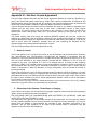
Data Acquisition System User Manual Data Acquisition System Document No. 20157 A © ViVitro Labs Inc. 2014 Page 1 of 25 Data Acquisition System User Manual ViVitro Labs Pulse Duplicator System Designed and Distributed by ViVitro Labs Inc., BC, Canada Disclaimer and Limitation of Responsibility ViVitro Labs Inc. assumes no responsibility for any damage, loss, or claims which may result from a failure to follow the instructions contained in this manual. Additionally, ViVitro Labs Inc. assumes no responsibility as a result of direct or derived injury, data loss, system malfunction which occurs at the fault of misuse, alternation of the system or incorrect application of use so advised or directed by ViVitro Labs. Copyright Copyright © 2014 by ViVitro Labs Inc. All rights reserved. Published by ViVitro Labs Inc. Victoria, British Columbia, Canada Limit of Liability/Disclaimer of Warranty: While the publisher and author have used their best efforts in preparing this document, they make no representation or warranties with respect to the accuracy or completeness of the contents of this document and specifically disclaim any implied warranties of merchantability or fitness for a particular purpose. No warranty may be created or extended by sales representatives or written sales material. The advice and strategies contained herein may not be suitable for your situation. Neither the Publisher nor author shall be liable for any loss of profit or any other commercial damages, including but not limited to special, incidental, consequential or other damages. No part of this publication may be reproduced, stored in a retrieval system or transmitted in any form or by any means, electronic, mechanical, photocopying, recording, scanning or otherwise without the prior written permission of the Publisher. Requests to the Publisher for permission should be addressed to: ViVitro Labs Inc. 455 Boleskine Rd Victoria, BC, Canada, V8Z 1E7 www.vivitrolabs.com [email protected] tel 250 388 3531 toll free 877 588 3531 fax 250 483 1975 Document No. 20157 A © ViVitro Labs Inc. 2014 Page 2 of 25 Data Acquisition System User Manual Table of Contents 1 About ViVitro Labs ........................................................................................................................... 4 2 Cautions and Warnings.................................................................................................................... 5 3 About this Manual............................................................................................................................. 6 4 About the Data Acquisition System ................................................................................................ 6 4.1 System Components.......................................................................................................................................6 4.2 Hardware Features .........................................................................................................................................6 5 Initial Set-Up Procedures ................................................................................................................. 7 5.1 6 Installing the Data Acquisition System ............................................................................................................7 AmPack Operation .......................................................................................................................... 13 6.1 Operation ...................................................................................................................................................... 13 6.2 Front Panel Controls ..................................................................................................................................... 13 7 System Calibration ......................................................................................................................... 14 8 Pressure Transducers .................................................................................................................... 15 9 Software ........................................................................................................................................... 15 10 Specifications ................................................................................................................................. 16 10.1 I/O Module Model 08311............................................................................................................................... 16 10.2 AmPack Model AP9991 ............................................................................................................................... 16 10.3 Pressure Transducer Model HCM018........................................................................................................... 17 10.4 Environmental (all devices) ........................................................................................................................... 17 11 Symbols ........................................................................................................................................... 17 Appendix I – AmPack Calibration ............................................................................................................ 18 Appendix II – I/O Module Re-Initialization After Reconnecting ............................................................ 19 Appendix III – End User License Agreement.......................................................................................... 20 1. Grant of License ........................................................................................................................................... 20 2. Ownership of the Software / Restrictions on Copying ................................................................................... 20 3. Other Restrictions on Use ............................................................................................................................. 21 4. Term ............................................................................................................................................................. 21 5. Responsibilty for Selection and Use of Software .......................................................................................... 21 6. Limited Warranty, Exceptions & Disclaimers ................................................................................................ 21 7. European Software Directive ........................................................................................................................ 22 8. General Provisions ....................................................................................................................................... 22 9. Canadian Sales ............................................................................................................................................ 23 Appendix IV – I/O Module Declarations of Conformity ......................................................................... 24 Appendix V – AmPack Declarations of Conformity ............................................................................... 25 Document No. 20157 A © ViVitro Labs Inc. 2014 Page 3 of 25 Data Acquisition System User Manual 1 About ViVitro Labs ViVitro Labs Inc. offers industry leading cardiovascular test equipment and related laboratory testing services. Hundreds of organizations in over 39 countries for 30+ years have trusted ViVitro’s expertise, accuracy, and quality for their cardiovascular device testing. As the developer of the world’s first Pulse Duplicator, the ViVitro name has been synonymous with cardiovascular device testing equipment. ViVitro hardware and software products have been used by leading R&D facilities and academic labs worldwide, and its equipment and testing methods being cited in hundreds of peer reviewed publications http://ViVitrolabs.com/company/cited-publications/. The ViVitro Labs’ Pulse Duplicator System (in particular the ViVitro Labs SuperPump) has become a worldwide standard to simulate physiological heart conditions in academic research applications. ViVitro products are manufactured by StarFish Medical in an ISO 13485:2003 certified manufacturing facility. ViVitro Labs Inc., also holds ISO/IEC 17025 accreditation for laboratory testing services endorsed by A2LA and based on ISO 5840. This scope of accreditation includes the physical and mechanical testing of heart valve substitutes including durability, hydrodynamic, and flow visualization testing. ViVitro Labs is widely recognized as the authority on cardiovascular device testing. ViVitro Laboratory Services are engaged worldwide for hydrodynamic, durability, and flow visualization testing of heart valves and other cardiac devices. ViVitro has been the trusted name in regulatory approvals for over 30 years and is renowned for its proven success from product development testing through to full regulatory submission. ViVitro Labs is a member of the ISO 5840 standards committee and is actively engaged in developing regulatory requirements. Leveraging this intimate knowledge of the standard, ViVitro Labs ensures that test protocols will meet ever changing regulatory requirements. ViVitro’s Laboratory Testing Services offers an ISO/IEC 17025 certified lab using ViVitro equipment, to conduct 3rd party independent testing. ViVitro’s accredited testing lab is governed by a mature Quality Management System (QMS) certified to meet the ISO 5840. This gives assurance to stakeholders and regulatory bodies that results are obtained by qualified personnel using traceable calibrated equipment and up to-date test methods, all supervised by a quality assurance department. Document No. 20157 A © ViVitro Labs Inc. 2014 Page 4 of 25 Data Acquisition System User Manual 2 Cautions and Warnings Prior to turning the AmPack on, ensure the line voltage switch at the back is set to the correct value. After you receive your Data Acquisition System, ensure that you let the electrical enclosures sit indoors at room temperature for at least one day before plugging them in. The systems must not be used in environments at higher than 75% humidity. Ensure the AmPack is situated such that the on/off switch located on the rear of the unit is accessible during operation. Ensure the AmPack is situated with sufficient clearance (> 75mm) at the rear to allow adequate air flow for cooling. Read all of the instructions before operating the System This instrument is intended for research use only and must be operated by trained lab personnel. Always connect the AmPack and PC power supplies to a grounded AC outlet using the AC power cords provided with the system. Do not use an adapter to an ungrounded outlet. Electrical devices pose the risk of electric shock. To reduce the risk of shock, do not open any covers that are fastened with screws. Clean the exterior of the AmPack and I/O Module housings with a dry cloth only. Disconnect power before cleaning Use caution when moving the system. Disconnect power before moving the system to a new location. Do not use the system if there is evidence of physical damage or if the system has been dropped or subject to impact. Do not attempt to service the product beyond what has been described in this manual. All other servicing should be referred to qualified service personnel. The user may opt to manipulate the system to achieve alternate states/results/configurations. Should the user carry this out it should be noted that exceeding the specified limits may compromise the accuracy of the digitized signal. Document No. 20157 A © ViVitro Labs Inc. 2014 Page 5 of 25 Data Acquisition System User Manual 3 About this Manual This document describes the Data Acquisition System’s procedures for: 1. 2. 3. 4. Assembly of the system’s hardware. Connection of the system’s electrical components. Calibration and system setup. Operator procedures for the system’s daily use. 4 About the Data Acquisition System 4.1 System Components The Data Acquisition System supplied by ViVitro Labs Inc. consists of: 4.2 I/O Module – Inputs/outputs signals from the software AmPack – Pressure Measuring System including transducers and amplifier Laptop computer Connecting cables Software (ViViTest, HiTest or QCTest) Hardware Features The Data Acquisition System from ViVitro Labs Inc. features include: Analog to digital conversion to collect all signals into a single USB input to the PC Available software makes the Data Acquisition System adaptable to any ViVitro test equipment Document No. 20157 A © ViVitro Labs Inc. 2014 Page 6 of 25 Data Acquisition System User Manual 5 Initial Set-Up Procedures There are seveal steps required in order to complete the installation and configuration of the electrical components of the DAS. It is important that these are followed in order to assure successful operation and functionality.Unpacking – list of components The Data Acquisition System arrives in a single container. Inspect the shipping container for external damage. Retain the shipping carton and packing materials for possible re-shipment. Inspect the system components for damage. If there is evidence of damage contact the carrier, initiate a damage claim, and inform ViVitro Labs. The Data Acquisition System arrives with the following parts: 1) AmPack: pressure signal conditioner and amplifier - 1, 36” BNC Cable - 3, 12” BNC Cables - 1 North American Power Cable - 1 trim pot adjustment tool 2) I/O Module: analog to digital converter with - 2, 36” BNC Cables - 3, 12” BNC Cables - 1 BNC T-Adapter - 1 USB Cable 3) Laptop Computer 5.1 1 North American Power Cable Installing the Data Acquisition System The components of the data acquisition system should be set up in a location which is protected from splash and spills from the test equipment. The AmPack may be placed on top of the I/O module. Ensure the AmPack is situated such that the on/off switch located on the rear of the unit is accessible during operation. NOTE: Check your country’s power supply amperage and voltage prior to connecting into a power supply ViVitro Labs Inc. will endeavor to have your system’s components adapted to meet your country’s power supply, however, as an extra precaution, it is advised that all equipment designated to be connected to a mains outlet be checked prior to use. 1. Check that the voltage setting on the back panel of the Flow meter and AmPack are set for your supply voltage BEFORE connecting to the mains outlet. Ensure that the operating voltage of the Heat Bath is correct for your region before connecting to the mains outlet. Document No. 20157 A © ViVitro Labs Inc. 2014 Page 7 of 25 Data Acquisition System User Manual 2. Where the voltage setting is incorrect adjust the setting manually according to the hardware’s instructions. The DAS is designed to be set up in the two following configurations: 5.1.1 Pulse Duplicator Set-Up: For use with ViViTest and QC Test Software 1. Connect the pressure transducer cables to the inputs of the AmPack as follows a. Aortic (Red) - top b. Ventricular (Yellow) - middle c. Atrial (Blue) - bottom 2. Connect the 3, 12” BNC connectors to the outputs of the AmPack. 3. Connect the 3, 12” BNC conncetors to following channels of the I/O Module: a. Aortic - top to channel 0 b. Ventricular - middle to channel 1 c. Atrial - bottom to channel 2 4. Connect the 36” BNC cable provided in the Flow Meter box to channel 4 of the I/O module. Connect the other end to the Pulse port on the Flow Measuring System. 5. Attach the ground wire to the Pulse Duplicator and plug it into the Flow Measuring System. 6. Connect the flow probe cable to meter. 7. Connect one 36” BNC cable to the Position port on the controller and connect the other end to channel 5 on the I/O module. 8. Connect one 36” BNC cable to the DL/DT port on the controller and connect the other end to channel 3 on the I/O module. 9. Connect one 36” BNC cable to the Waveform In port on the controller and connect the other end to analog output chanel 0 on the I/O module. 10. Connect the USB cable between the I/O Module and the Laptop computer. Document No. 20157 A © ViVitro Labs Inc. 2014 Page 8 of 25 Data Acquisition System User Manual Document No. 20157 A © ViVitro Labs Inc. 2014 Page 9 of 25 Data Acquisition System User Manual 5.1.2 HiCycle/RWT Set-Up: For use with HiTest Software 1. Connect the pressure transducer cables to the inputs of the AmPack as follows a. Outflow (Red) - bottom b. Inflow (Blue) - middle 2. Connect 2, 12” BNC cables to the outputs of the bottom and middle AmPack channels 3. Connect the 2, 12” BNC cables to the following channels on the I/O Module: a. Outflow - bottom to channel 0 b. Inflow - middle to channel 1 4. Connect the BNC T connector to channel 6 on the I/O Module. Connect one side of the T to channel 3 using a 12” BNC cable. 5. Connect one 36” BNC cable from the Sync output of the controller to the other side of the T. 6. Connect the USB cable between the I/O Module and the Laptop computer. Document No. 20157 A © ViVitro Labs Inc. 2014 Page 10 of 25 Data Acquisition System User Manual Document No. 20157 A © ViVitro Labs Inc. 2014 Page 11 of 25 Data Acquisition System User Manual Document No. 20157 A © ViVitro Labs Inc. 2014 Page 12 of 25 Data Acquisition System User Manual 6 AmPack Operation 6.1 Operation 1. Set the voltage on the back panel of the AmPack. chassis for your line voltage. Be sure to select 115 or 230 VAC appropriate to your line voltage. AN INCORRECT VOLTAGE SETTING MAY CAUSE DAMAGE TO THE UNIT. NOTE: The fuse located on the rear panel should be ¼A MDL. 2. Ensure the proper power cord for your countries outlet is available. Insert the rectangular power plug into the rear panel receptacle. The other end should be plugged into the mains supply. 3. Plug the white pressure transducer cables into the input connector on the front panel of the amplifiers. Fasten all clamping screws using the trim pot adjuster tool to ensure optimum signal to noise ratio and stability. NOTE: Keep moisture away from all electrical connectors and the transducer case. 4. To power the unit on, use the toggle switch on the rear panel. Allow the amplifiers to warm up for 30 minutes to achieve minimum drift. Warm up time can be avoided by leaving the unit on continuously. This will not damage the system. 5. Select the desired filters using the filter switch located on the front panel of each amplifier. NOTE: For Pulse Duplicator measurements 30 Hz or 100 Hz is recommended. For measurement of pressure in accelerated cycling tests 1000 Hz is recommended. 6.2 Front Panel Controls INPUT: Always use the locking screws on the cable connectors. GAIN: Adjustable by 15 turn potentiometer. FILTERS: A five position switch selects upper frequency cut-off. Normally this should be lower than the natural frequency of the transducer. The system frequency response may be limited by fluid filled catheter lines. In the OFF position the full amplifier bandwidth is available (nominal 0-200 kHz). SHIFT: 15-turn potentiometer; each turn shifts output 2.5 volts between full scale ±12 volts. OUTPUT: BNC connector - between -12 and +12 volts. The amplifier is stable with capacitive loads to 100 pF. Document No. 20157 A © ViVitro Labs Inc. 2014 Page 13 of 25 Data Acquisition System User Manual 7 System Calibration ViVitro Labs Inc. normally pre-sets the pressure calibration of the AmPack to values suitable for monitoring either heart valve hydrodynamic tests or durability tests. The I/O module in either case is set for an input range of -10 to +10 V. The factory system calibration values are: Pulse Duplicator: -50 to +250 mmHg = -9 to +9 V HiCycle/RWT: -200 to +250 mmHg = -9 to +9 V NOTE: To avoid poor signal to noise ratio and recording of erroneous data, the full scale capability of recording instruments should be matched to the range of the dynamic signals to be measured. If your testing application involves pressures outside of the above limits, the AmPack calibration should be adjusted to suit. The system should be checked periodically to ensure no drift has occurred. When the transducers are exposed to atmosphere, check that outputs read zero When the transducers are exposed to a known pressure (verify with a calibrated manometer) outputs should be within an acceptable tolerance Document No. 20157 A © ViVitro Labs Inc. 2014 Page 14 of 25 Data Acquisition System User Manual Periodic re-calibration is suggested. Tracking of calibration trends may help establish calibration frequency. Appendix I contains instructions for calibrating the AmPack. 8 Pressure Transducers The pressure transducers supplied are disposable in clinical application. For pressure measurements in a fluid, the transducer should be filled with fluid and de-bubbled. For repeated use in vitro, distilled water is recommended. Excessive tightening of the Luer lock cap should be avoided. Pressure transducer may be damaged by over-pressure. This can occur if a finger occludes the transducer pressure port during transducer flushing. Rapid stopcock closure may also produce excess pressure. Please contact ViVitro Labs Inc. regarding use of other pressure transducers with the ViVitro Labs Inc. Model AP9991 amplifiers (e.g. Millar catheter tip MPC500). 9 Software For information on the software installed on the PC supplied with the Data Acquisition system, refer to the system specific user manual. 1. ViViTest (see Pulse Duplicator User Manual) 2. ViViGen (see Pulse Duplicator User Manual) 3. HiTest (see HiCycle User Manual or RWT User Manual) 4. QCTest (see Function Tester User Manual) Document No. 20157 A © ViVitro Labs Inc. 2014 Page 15 of 25 Data Acquisition System User Manual 10 Specifications 10.1 I/O Module Model 08311 power supply ................................................................................................................ 5 VDC from USB, x mW dimensions ............................................................................................................ (w x l x h) 255 x 265 x 83 mm total weight .............................................................................................................................................. 1.85 kg Analog Inputs Ranges: ................ Software selectable on a perchannel basis, ±10 V, ±5 V, ±2 V, ±1 V, ±0.5 V, ±0.2 V, ±0.1 V Input Impedance: ..........................................................................10 MOhm single-ended;20 MOhm differential Input connector ............................................................................................................................................ BNC Digital Input Voltage Range (Ch6): .................................................................................................................................0 - 5 V Input connector ............................................................................................................................................ BNC Analog Out Resolution: .................................................................................................................................................. 16 bits Output Voltage Range: ................................................................................................................................. ±10 V Output Current: ................................................................................................................................... ±1 mA max Output connector .......................................................................................................................................... BNC 10.2 AmPack Model AP9991 power supply .................................................... 115/230 ±10% volts AC (switch selectable) 50-60 Hz, 10 watts protection ................................................................................................................................... ¼ A -MDL fuse dimensions .......................................................................................................................... 255 x 150 x 130 mm total weight (with three amplifiers inserted) .............................................................................................. 2.7 kg AMPLIFIER excitation voltage ................................................................................................................... ±2.5 volts, ±0.3% excitation current .................................................................................................................................. < 20 mA transducer resistance ........................................................................................... any provided current < 20 mA configuration ........................................................ 4-arm resistive or piezo-resistive shear stress semiconductor input impedance ..................................................................................................................... 10k ohms at 0 Hz input configuration ............................................................................................................................ differential gain linearity ................................................................................................................................ 0.1% full scale gain stability .................................................................................................... 1% of value / 8 hours, 0.05% / ºC zero stability ........................................................................................ ±1 mmHg/ 8 hours (30 minute warm up) common mode rejection .......................................................................................................... >60 dB, 0-60 Hz maximum common mode operating voltage ................................................................... 5 volts DC or peak AC maximum safe input ....................................................................................................... 12 volts DC or peak AC output noise, mvolt (sensitivity = 33 mvolt/mmHg):.......................................................................... < 0.1 mvolts frequency response: unfiltered - OFF .................................................................................................................................. 0-200 kHz filtered – 4 selections, standard values are ............................................................ 0 to 30, 100, 1000, 10,000 Hz .................................................................................................. 2 pole Butterworth 12 dB/octave (40 dB/decade) (optional filter modules are available) output full scale .............................................. ±9.5 volts, ±25 mA max. into 50 ohms capacitive loads to 100 pF protection ........................................................................................................................ thermal and short circuit input connector ..................................................................................................... 9-pin female D-subminiature output connector .......................................................................................................................................... BNC Document No. 20157 A © ViVitro Labs Inc. 2014 Page 16 of 25 Data Acquisition System User Manual 10.3 Pressure Transducer Model HCM018 Operating Range ................................................................................................................ -50 to +300 mmHg Sensitivity .................................................................................. 5.0 volts/volt/mmHg ±2% (typically <±1%) Non-linearity & hysteresis ................................................. ±1% of reading or ±1 mmHg (whichever is greater) Zero Offset .................................................................................................................................... < ±40 mmHg Zero Thermal effect ................................................................................................................ < ±0.3 mmHg/ ºC Output Drift ......................................................................................................................... < 1 mmHg / 8 hours Natural Frequency ................................................................................................................. > 200 Hz in water Leakage Current ................................................................................................ < 2 µA at 120 volts RMS 60 Hz Overpressure ................................................................................................................... -400 to +4,000 mmHg Light Sensitivity .................................................................... < 1 mm Hg at 6 volts excitation when exposed to a 3,400 ºK tungsten light source at 3,000 foot candles Volumetric Displacement < 0.03 mm3/100 mmHg 10.4 Environmental (all devices) Temperature Humidity Pressure Operating 10-35°C 30-85% non-condensing 110-80 kPa Storage -15-55°C 5-95% non-condensing 110-80 kPa Shipping -15-55°C 5-95% non-condensing 110-80 kPa 11 Symbols Product was shown to comply with the applicable regulations in the European Community. Attention, consult the accompanying instructions for use. Date of manufacture. Indicates the serial number of the product On/off Document No. 20157 A © ViVitro Labs Inc. 2014 Page 17 of 25 Data Acquisition System User Manual Appendix I – AmPack Calibration Each amplifier module and pressure transducer may be calibrated following the procedure given below. You will need a reference pressure gauge. A manometer with a range of at least 250 mmHg and accuracy of at minimum ±0.025% is suitable. You will need a means of reading amplifier output between -10.00 and +10.00 volts DC to an accuracy > than the pressure gauge accuracy. Use the supplied trim-pot tool to adjust the 15-turn potentiometers for GAIN & SHIFT. The extreme position, indicated by a click, may be located by rotation of at least 15 turns clockwise or anti-clockwise. Ensure the AmPack has been on for at least 30 minutes prior to calibration to prevent drift.A two point pressure transducer calibration can be made as follows: 1. Connect amplifiers to pressure transducers and switch amplifier chassis power ON. 2. Use a syringe to fill the pressure transducers with distilled water. 3. Adjust the SHIFT control to give the desired voltage output at 0 mmHg gage pressure (atmospheric). a. -5.9 to -6.1 VDC for Pulse Duplicator b. -0.9 to -1.1 VDC for HiCycle/RWT 4. Apply a pressure of +200 mmHg to transducers and adjust GAIN for the target voltage output. a. +5.9 to +6.1 VDC for Pulse Duplicator b. +6.9 to +7.1 VDC for HiCycle/RWT 5. Repeat steps 3 and 4 the desired sttings at both limits are achieved. 6. Below are the approximate values that will be achieved from the calibrations described above (CALIBRATION = Δ voltage/ Δ pressure): a. 0.06 V/mmHg for Pulse Duplicator b. 0.04 V/mmHg for HiCycle/RWT The GAIN and SHIFT settings may need to be changed depending on the range of pressure generated in the specific application. Different settings may be needed for monitoring the ViVitro Labs Inc. pulse duplicator and the Hi-Cycle. tester. Changing GAIN will also change the output at atmospheric pressure. It may be necessary to re-adjust SHIFT until the required outputs are obtained at the two calibration pressures. The factory preset values shown above are based on the following: 1. Application: Hydrodynamic Testing (probable pressure range -50 to 250 mmHg) 2. Application: Durability Testing (probable pressure range -200 to 200 mmHg) Document No. 20157 A © ViVitro Labs Inc. 2014 Page 18 of 25 Data Acquisition System User Manual Appendix II – I/O Module Re-Initialization After Reconnecting In cases where the I/O Module is reconnected and needs re-initialization the following sequence is recommended: 1. Remove the I/O Module USB cable from the PC. 2. Wait 10 seconds and then re-insert the USB cable to the PC. 3. Navigate to InstaCal icon on your desktop and double click 4. Highlight the board number in the detection box and click OK 5. Right click on the board number in the InstaCal box and select configure. 6. Confirm settings are set to: a. 8 differential channels b. Factory calibration c. XAPCR Edge = Rising d. XAPCR Pin direction = input e. XDPCR Edge = Rising f. XDPCR pin direction = input g. ADC settling time = 10us 7. Click OK 8. Right click on the board number in the InstaCal box and select Calibrate – A/D 9. Click Calibrate 10. Click OK and Exit program. Document No. 20157 A © ViVitro Labs Inc. 2014 Page 19 of 25 Data Acquisition System User Manual Appendix III – End User License Agreement The terms and conditions that follow set forth a legal agreement between you (either an individual or an entity), and ViVitro Labs (herein referred to as “ViVitro Labs”) with its principal place of business at 455 Boleskine Road, Victoria, BC Canada V8Z 1E7, relating to the computer software known as ViViTest and certain other related software modules, if applicable (herein referred to as "Software"). The term Software includes and these terms and conditions also apply to, any updates or upgrades to the Software that you may receive from time to time under a subscription service or other support arrangement. You may not load or use the Software in any computer or copy it without a license from ViVitro Labs. ViVitro Labs hereby offers you a non-exclusive license on the terms set out in this Agreement. You should carefully read these terms and conditions BEFORE opening the case that contains the Software or installing and using the Software. Opening the case containing the Software or installing and using the Software will signify your agreement to be bound by these terms and conditions. If you do not agree to these terms and conditions, promptly return the case containing the Software and the accompanying items (including written materials) for a refund. This is a license agreement and not an agreement for sale. 1. Grant of License ViVitro Labs grants to you a nonexclusive license to use the Software and the printed and/or electronic user documentation (the "Documentation") accompanying the Software in accordance with this Agreement. If you have paid the license fee for a single user license, this Agreement permits you to use one copy of the Software on any single computer, provided that the Software is in use on only one computer at any time. The Software is "in use" on a computer when it is loaded into the temporary memory (i.e. RAM). If the potential number of users of the Software exceeds the number of licenses you have purchased, then you must have a reasonable mechanism or process in place to assure that the number of computers on which the Software is running concurrently does not exceed the number of licenses purchased. ViVitro Labs reserves the right to embed a software security mechanism within the Software to monitor usage of the software to verify your compliance with this license. Such a security mechanism may store data relating to the use of the Software and the number of times it has been copied. ViVitro Labs reserves the right to use a hardware lock device, license administration software, and/or a license authorization key to control access to the Software. You may not take any steps to avoid or defeat the purpose of any such measures. Use of any Software without any required lock device or authorization key is prohibited. 2. Ownership of the Software / Restrictions on Copying ViVitro Labs or its licensors own and will retain all copyright, trademark, trade secret and other proprietary rights in and to the Software and the Documentation. THE SOFTWARE AND THE DOCUMENTATION ARE PROTECTED BY COPYRIGHT LAWS AND OTHER INTELLECTUAL PROPERTY LAWS. You obtain only such rights as are specifically provided in this Agreement. You may copy the Software into any machine-readable form for back-up purposes and within the license restrictions. You may not remove from the Software or Documentation any copyright or other proprietary rights notice or any disclaimer, and you shall reproduce on all copies of the Software made in accordance with this Agreement, all such notices and disclaimers. Document No. 20157 A © ViVitro Labs Inc. 2014 Page 20 of 25 Data Acquisition System User Manual 3. Other Restrictions on Use This Agreement is your proof of license to exercise the rights granted herein and must be retained by you. You may not use any portion of the Software separately from or independently of the Software and other than for your normal business purposes. You may not provide access to or use of the Software to any third party; consequently you may not sell, license, sublicense, transfer, assign, lease or rent (including via an application service provider (ASP) or timeshare arrangement) the Software or the license granted by this Agreement. You may not modify or make works derivative of the Software and you may not analyze for purposes competitive to ViViTest, reverse engineer, decompile, disassemble or otherwise attempt to discover the source code of the Software, except in accordance with the following, if applicable, as it contains trade secrets of ViVitro Labs and its licensors. 4. Term The license granted herein will continue until it is terminated in accordance with this term. ViVitro Labs may terminate the license granted herein immediately upon written notice to you (i) for justified cause, including without limitation breach of any provision of this Agreement, or (ii) if you breach any provision of this Agreement and fail to cure such breach within fifteen (15) days of notice thereof. Upon the termination of the license, you will promptly return to ViVitro Labs or destroy all copies of the Software and Documentation covered by the license as instructed by ViVitro Labs. 5. Responsibilty for Selection and Use of Software You are responsible for the supervision, management and control of the use of the Software, and output of the Software, including, but not limited to: (1) selection of the Software to achieve your intended results; (2) determining the appropriate uses of the Software and the output of the Software in your business; (3) establishing adequate independent procedures for testing the accuracy of the Software and any output; and (4) establishing adequate backup to prevent the loss of data in the event of a Software malfunction. 6. Limited Warranty, Exceptions & Disclaimers a. Limited Warranty. ViVitro Labs warrants that the Software will be free of defects in materials and workmanship and will perform substantially in accordance with the Documentation for a period of ninety (90) days from the date of receipt by you. ViVitro Labs also warrants that any services it provides from time to time will be performed in a work-person-like manner in accordance with reasonable commercial practice. ViVitro Labs entire liability and your sole remedy under this warranty shall be to use reasonable efforts to repair or replace the nonconforming media or Software or re-perform the service. If such effort fails ViVitro Labs shall (i) refund the price you paid for the Software upon return of the nonconforming Software and a copy of your receipt or the price you paid for the service, as appropriate, or (ii) provide such other remedy as may be required by law. Any replacement Software will be warranted for the remainder of the original warranty period or thirty (30) days from the date of receipt by you, whichever is longer. b. Exceptions. ViVitro Labs limited warranty is void if breach of the warranty has resulted from (i) accident, corruption, misuse or neglect of the Software; (ii) acts or omissions by someone other than ViVitro Labs; (iii) combination of the Software with products, material or software not provided by ViVitro Labs or not intended for combination with the Software; or (iv) failure by you to incorporate and use all updates to the Software available from ViVitro Labs. ViVitro Labs does not warrant that the Software or service will meet your requirements or that the operation of the Software will be uninterrupted or error free. Document No. 20157 A © ViVitro Labs Inc. 2014 Page 21 of 25 Data Acquisition System User Manual c. Limitations on Warranties. The express warranty set forth in 8.6.6 is the only warranty given by ViVitro Labs with respect to the Software and Documentation furnished hereunder and any service supplied from time to time; ViVitro Labs and its licensors, to the maximum extent permitted by applicable law, make no other warranties, express, implied or arising by custom or trade usage, and specifically disclaim the warranties of merchantability and fitness for a particular purpose. In no event may you bring any claim, action or proceeding arising out of the warranty set forth in 5.1.6 more than one year after the date on which the breach of warranty occurred. d. Limitations on Liability. Except as required under local law, the liability of ViVitro Labs and its licensors, whether in contract, tort (including negligence) or otherwise, arising out of or in connection with the Software or Documentation furnished hereunder and any service supplied from time to time shall not exceed the license fee you paid for the Software or any fee you paid for the service. In no event shall ViVitro Labs or its licensors be liable for special, indirect, incidental, punitive or consequential damages (including without limitation damages resulting from loss of use, loss of data, loss of profits, loss of goodwill or loss of business) arising out of or in connection with the use of or inability to use the Software or Documentation furnished hereunder and any service supplied from time to time, even if ViVitro Labs or its licensors have been advised of the possibility of such damages. Notwithstanding the foregoing, in no event shall ViVitro Labs' liability be limited in the case of death or personal injury arising as a result of the negligence or willful misconduct of ViVitro Labs. 7. European Software Directive If the provisions of the Council of European Communities Directive of May 14, 1991 on the Legal Protection of Computer Programs as implemented in applicable national legislation (the "Software Directive") apply to your use of the Software, and you wish to obtain the information necessary to achieve interoperability of an independently created computer program with the Software as permitted under the Software Directive ("Interoperability Information"), you must notify ViVitro Labs in writing, specifying the nature of the Interoperability Information you need and the purpose for which it will be used. If ViVitro Labs reasonably determines that you are entitled to such Interoperability Information under the Software Directive, ViVitro Labs Inc shall, at its option, either (i) provide such Interoperability Information to you, or (ii) allow you to reverse engineer the Software, within the limits and for the purposes prescribed by the Software Directive, solely to the extent indispensable to obtain such Interoperability Information. If ViVitro Labs Inc elects clause (i), you will provide any information and assistance reasonably requested by ViVitro Labs Inc to enable ViVitro Labs Inc to perform clause (i), and ViVitro Labs Inc may charge you a reasonable fee for making available the requested Interoperability Information, unless such a fee is prohibited under the Software Directive. 8. General Provisions You acknowledge that the Software and the Documentation may be subject to the export control laws of the United States or the United Kingdom and agree not to export or re-export the Software or the Documentation (i.e., move the Software from the country in which you first licensed it) without the appropriate United States or foreign government licenses and the written approval of ViVitro Labs Inc and its licensors. The United Nations Convention on Contracts for the International Sale of Goods (1980) is here by excluded in its entirety from application to this License Agreement. The English language version of this Agreement shall be the authorized text for all purposes, despite translations or interpretations of this Agreement into other languages. If for any reason a court of competent jurisdiction finds any provision of this Agreement, or a portion thereof, to be unenforceable, that provision shall be enforced to the maximum extent permissible and the remainder of this Agreement shall remain in full force and effect. Document No. 20157 A © ViVitro Labs Inc. 2014 Page 22 of 25 Data Acquisition System User Manual 9. Canadian Sales If you purchased this product in Canada, you agree to the following: The parties hereto confirm that it is their wish that this Agreement, as well as other documents relating hereto, including Notices, have been and shall be written in the English language only. Les parties aux présentes confirment leur volunté que cette convention de même que tous les documents y compris tout avis qui s'y rattache, soient rédigés en langue anglaise. You further agree that this Agreement is the complete and exclusive statement of your agreement with ViVitro Labs Inc relating to the Software and subscription service and supersedes any other agreement, oral or written, or any other communications between you and ViVitro Labs Inc relating to the Software and subscription service; provided, however, that this Agreement shall not supersede the terms of any signed agreement between you and ViVitro Labs Inc relating to the Software and subscription service. ViVitro Labs warrants all parts of its own manufacture to be free from defects in material and workmanship under normal use and service in a suitable environment for the period of one year after delivery. Document No. 20157 A © ViVitro Labs Inc. 2014 Page 23 of 25 Data Acquisition System User Manual Appendix IV – I/O Module Declarations of Conformity Application of Council Directives: 2004/108/EC Standards to which conformity is declared: EN 61326-1:2013 Manufacturer: ViVitro Labs Inc. 455 Boleskine Road Victoria, BC V8Z 1E7 Canada Type of device: Analog/Digital Converter Model: 08311 Year of initial CE Marking: 2014 I hereby declare that the device named above has been tested and found to comply with the above referenced Directives and Standards. Name: Gerry Wight Position: General Manager Done at: Victoria, BC, Canada On: 15 July 2014 Document No. 20157 A © ViVitro Labs Inc. 2014 Page 24 of 25 Data Acquisition System User Manual Appendix V – AmPack Declarations of Conformity Application of Council Directives: 2006/95/EC 2004/108/EC Standards to which conformity is declared: EN 61010-1:2010 EN 61326-1:2013 Manufacturer: ViVitro Labs Inc. 455 Boleskine Road Victoria, BC V8Z 1E7 Canada Type of device: Transducer Signal Conditioner Model: AP9991 Year of initial CE Marking: 2009 I hereby declare that the device named above has been tested and found to comply with the above referenced Directives and Standards. Name: Gerry Wight Position: General Manager Done at: Victoria, BC, Canada On: 15 July 2014 Document No. 20157 A © ViVitro Labs Inc. 2014 Page 25 of 25