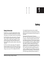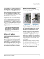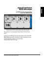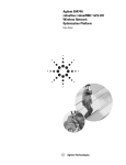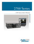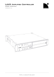
1
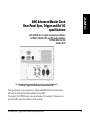
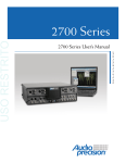
APx555 audio analyzer Installation Instructions and Specifications model APx555 October, 2014 Copyright © 2006–2014 Audio Precision, Inc. All rights reserved. Printed in the United States of America. No part of this manual may be reproduced or transmitted in any form or by any means, electronic or mechanical, including photocopying, recording, or by any information storage and retrieval system, without permission in writing from the publisher. AUDIO PRECISION, the AUDIO PRECISION logo and the AP logo are trademarks of Audio Precision and are registered in the U.S. Patent and Trademark Office and in other countries. Windows™ is a trademark of Microsoft Corporation. Dolby and the double-D symbol are trademarks of Dolby Laboratories, Inc. DTS is a trademark of DTS, Inc. Audio Precision 5750 SW Arctic Drive Beaverton, Oregon 97005 503-627-0832 800-231-7350 ap.com pn 8211.0335 rev 000 XIV1014062852 Documentation and Support This booklet contains safety information, installation instructions and full specifications for the Audio Precision APx555 audio analyzer. The APx500 User’s Manual Detailed information on the operation of the APx555 is available from the embedded Help installed with the APx500 measurement software, and in the APx500 User’s Manual, included with the analyzer. The user’s manual is also available as a PDF on the APx500 Application Disc and on the Web at ap.com; additional copies can be ordered from Audio Precision or your local distributor. Audio Test Discs These discs are included with your analyzer system: • APx-DVD1 is a playable video DVD with menu-driven linear and coded audio test signals for external source use with DVD players. • APx-CD1 is a playable audio CD with linear audio test signals for external source use with CD players. ap.com Visit the Audio Precision Web site at ap.com for APx support information. APx resources are available at ap.com/downloads/apx. You can also contact our Technical Support staff at [email protected], or by telephoning 503-627-0832 extension 4, or 800-231-7350 extension 4 (toll free in the U.S.A.). Table of Contents Safety . . . . . . . . . . . . . . . . . . . Installation . . . . . . . . . . . . . . . . . Abbreviations, Terms and Symbols . . . . APx555 analog I/O specifications . . . . . ADIO specifications . . . . . . . . . . . . DSIO specifications . . . . . . . . . . . . HDMI+ARC specifications . . . . . . . . . Bluetooth specifications . . . . . . . . . . PDM specifications . . . . . . . . . . . . AMC specifications . . . . . . . . . . . . General and Environmental specifications . . . . . . . . . . . . . . . . . . . . . . APx555 Audio Analyzer: Table of Contents . . . . . . . . . . . . . . . . . . . . . . . . . . . . . . . . . . . . . . . . . . . . . . . . . . . . . . . . . . . . . . . . . . . . . . . . . . . . . . . . . . . . . . . . . . . . . . . . . . . . . . . . . . . . . . . . . . . . . . . . . . . . . . . . . . . . . . . . . . . . . . . . . . . . . . . . . . . . . . . . . . . . . . . . . . . . . . . . . . . . . . . . . . . . . . . . . . . . . . . . . . . . . . . . . . . . . . . . . . . . . . . . . . . . . . . . . . . . . . . . . . . . . . . . . . . . . . . . . . . . . . . . . . . . . . . . . . . . . . . . . . . . . . . . . . . . . . . . . . . . . . . . . . . . . . . . . . . . . . . . . . . . . . . . . . . . . . . . . . . . . . . . . . . . . . . . . . . . . . . . . . . . . . . . . . . . . . . . . . . . . . . . . . . . . . . . . . . . . . . . . . . . . . . . . . . . . . . . . . . . . . . . . . . . . . . . . . . . . . . . . . . . . . . . . . . . . . . . . . . . . . . . . . . . . . . . . . . . . . . . . . . . . iii . 1 . 5 . 7 . 19 . 29 . 35 . 41 . 43 . 49 . 53 i Chapter 1: Table of Contents ii APx555 Audio Analyzer: Table of Contents 1 Safety Safety Information Do NOT service or repair this equipment unless properly qualified. Servicing should be performed only by a qualified technician or an authorized Audio Precision distributor. Do NOT defeat the safety ground connection. This equipment is designed to operate only with an approved threeconductor power cord and safety grounding. Loss of the protective grounding connection can result in electrical shock hazard from the accessible conductive surfaces of this equipment. Do NOT exceed mains voltage ratings. This equipment is designed to operate only from a 50–60 Hz ac mains power source at 100–240 Vac nominal voltage. The mains supply voltage is not to exceed ±10 % of nominal (90–264 Vac). APx555 Audio Analyzer: Safety Information For continued fire hazard protection, fuses should be replaced ONLY with the exact value and type indicated on the rear panel of the instrument and discussed on page 4 of this manual. The International Electrotechnical Commission (IEC 1010-1) requires that measuring circuit terminals used for voltage or current measurement be marked to indicate their Measurement Category. The Measurement Category is based on the amplitude of transient or impulse voltage that can be expected from the AC power distribution network. This product is classified as Measurement Category I, abbreviated “CAT I” on the instrument front panel. This product should not be used within Categories II, III, or IV. The 2-channel input module measurement terminals are rated for a maximum voltage of 230 Vpk to ground, and a signal input of 160 Vrms unbalanced, 300 Vrms balanced; the 8-channel input module measurement terminals are iii Chapter 1: Safety rated for a maximum input of 160 Vpk to ground, and a signal input of 115 Vrms, balanced or unbalanced. These terminals are intended to be used for the measurement of audio signals only. Do NOT substitute parts or make any modifications without the written approval of Audio Precision. Doing so may create safety hazards. Using this product in a manner not specified by Audio Precision can result in a safety hazard. This product is for indoor use—Installation Category II, Measurement Category I, pollution degree 2. Safety Symbols could damage equipment. If you see this marked on equipment, refer to the Operator’s Manual or User’s Manual for precautionary instructions. FUNCTIONAL EARTH TERMINAL—A terminal marked with this symbol is electrically connected to a reference point of a measuring circuit or output and is intended to be earthed for any functional purpose other than safety. The following symbols may be marked on the panels or covers of equipment or modules, and are used in this manual: WARNING!—This symbol alerts you to a potentially hazardous condition, such as the presence of dangerous voltage that could pose a risk of electrical shock. Refer to the accompanying Warning Label or Tag, and exercise extreme caution. PROTECTIVE EARTH TERMINAL—A terminal marked with this symbol is bonded to conductive parts of the instrument and is intended to be connected to an external protective earthing system. Disclaimer Audio Precision cautions against using their products in a manner not specified by the manufacturer. To do otherwise may void any warranties, damage equipment, or pose a safety risk to personnel. ATTENTION!—This symbol alerts you to important operating considerations or a potential operating condition that iv APx555 Audio Analyzer: Safety Information Chapter 1: Safety APx555 Audio Analyzer: Safety Information v APx555 Audio Analyzer: Installation 2 Installation Software All APx systems use the same award-winning measurement software, APx500. PC system requirements The APx500 measurement software version 4.0 and later requires a personal computer (PC) with the following features and capabilities: • Operating system: Microsoft Windows 8, Windows 7 or Windows Vista. • A multi-core processor (at least dual-core) running at a clock speed of at least 2 GHz. Most current processors from Intel and AMD meet these requirements. Note: the Intel Atom processor does not meet our minimum specification. APx555 Audio Analyzer: Installation • • • • At least 2 GB of RAM. At least 300 MB of free hard disk space. A CD-ROM optical disc drive. A USB 2.0 port; two are required for optional switcher or DCX-127 use. • A color monitor and a video card with at least VGA capabilities. Video resolution of 1024 x 768 or greater is recommended. System performance is sensitive to processor speed; faster processors will yield faster results. APx500 is data intensive and it is recommended that other data-intensive applications not be run concurrently. This includes Audio Precision’s AP2700, APWIN or ATS. 1 Chapter 2: Installation Installation To install the measurement software, insert the APx500 CDROM into the optical drive on the PC and follow the instructions in the installation dialog. NOTE: You must have local administrator rights to install APx500 software. Go to User Accounts in the Windows Control Panel, or check with your network administrator. Running the software without instrument hardware attached You can launch the APx500 software without instrument hardware attached. When no hardware is detected, APx500 will present you with the following dialog box: Select “Demo Mode.” APx500 will run in demo mode, which allows you to explore the user interface but does not enable any measurement functions. Input data shown in Demo Mode is false data, generated for display only. From the Instrument Type menu, select an instrument to be emulated in Demo Mode. 2 Running the software with instrument hardware attached NOTE: You must have standard user rights or administrator rights to operate APx500 software. Guest users are not supported. Connecting the instrument to your PC Before connecting your APx instrument to your PC, install the APx500 measurement software as described above. Connecting the instrument prior to software installation may cause Windows to select an incorrect USB driver for the instrument. USB driver selection The measurement software communicates with the instrument using a USB 2.0 interconnection. Once the software is successfully installed, connect one end of the USB cable to a USB 2.0 port on the PC, and the other end to the PC INTERFACE port on the rear of the instrument. We strongly recommend that you use the USB cable included with your instrument (AP order number CAB-APSI). We have tested other USB cables that perform poorly. Note: Some PCs have optional USB ports on the front of the PC, or on extension brackets on the rear. In many cases these convenience ports have compromised performance due to the extra cable length within the PC. We recommend using USB ports directly connected to the PC motherboard, typically at the rear of the PC. Connect the instrument mains power cord to the instrument and to a source of ac mains power. See Setting up the hardware below for more information about mains connections. APx555 Audio Analyzer: Installation Chapter 2: Installation Turn the instrument ON by pressing the pushbutton on the front of the instrument. Microsoft Windows will detect the presence of the instrument on the USB and will open the Hardware Update Wizard to search for the correct software driver. Select “Install the software automatically.” Windows will find the Audio Precision driver software installed with APx500 and connect to the instrument. Launch APx500 by double-clicking on the installed shortcut. With the instrument connected, you may be asked to update the instrument firmware during the first launch of the measurement software. APx500 will start, and in a short time you will be presented with the opening screen. Refer to the APx500 User’s Manual for more information about making measurements. A copy of the APx500 User’s Manual is included with your instrument. The manual is also available as a PDF on the APx500 Application Disc and online at ap.com. Setting up the hardware Connecting your instrument to the electrical mains supply The APx500 series instrument must be connected to a 50– 60 Hz alternating current (ac) electrical mains supply. The minimum voltage is 90 Vac; maximum voltage is 264 Vac. The instrument is fitted with a universal power supply that does not require voltage configuration or change of fuse type to accept mains voltages within the specified range. APx555 Audio Analyzer: Installation Removing and installing mains fuses To remove the mains fuse carrier module, refer to the figures below and proceed as follows: Power entry module Fuse carrier removal Remove the mains power supply cord from the connector on the power entry module, located on the instrument rear panel. The mains fuse carrier module is part of the power entry module, to the right of the power cord connector. Insert a small screwdriver into the power cord connector area, reaching into the slot on the mains fuse carrier module. Pry the module out slightly, until you can grasp the module firmly with your fingers. Pull the fuse carrier module out of the power entry module. The two mains fuses are loosely mounted within the fuse carrier module; take care not to let them fall. Replace the fuses if necessary, using fuses as described below. Carefully reinsert the fuse carrier module into the power entry module, and press it firmly into place. Connect the power cord from a mains power outlet to the power cord connector on the instrument rear panel. 3 Chapter 2: Installation Fuse Information APx500 series instruments are fitted with a universal power supply. For all rated voltages, use two mains fuses of type 2A T/SB (5 x20 mm) 250 V. 4 APx555 Audio Analyzer: Installation Abbreviations, Terms and Symbols used in the following specifications ADC or A/D . . . . . . . . Analog to Digital converter or conversion. BW . . . . . . . . . . . . . . . Bandwidth or Measurement Bandwidth, nominally at –3 dB; a single number indicates only the upper limit. DAC or D/A . . . . . . . . Digital to Analog converter or conversion. DSP . . . . . . . . . . . . . . . Digital Signal Processing or Digital Signal Processor. DUT . . . . . . . . . . . . . . Device Under Test, the device to which the generator or analyzer is connected. EMC . . . . . . . . . . . . . . Electro-Magnetic Compatibility, usually refers to both emissions (radiated and conducted via AC mains) and susceptibility. ENBW . . . . . . . . . . . . . Equivalent Noise Bandwidth, the frequency of an ideal filter having the same rms response to white noise. FFT . . . . . . . . . . . . . . . Fast Fourier Transform, a mathematical process converting a signal in the time domain to the frequency domain. IMD . . . . . . . . . . . . . . . Inter-Modulation Distortion, a measure of non-linearity using a test signal with two or more components. RMS or rms . . . . . . . . . Root Mean Square, an equivalent-power expression of signal amplitude. SR . . . . . . . . . . . . . . . . Sample Rate, usually as it applies to the conversion rate of A/D and D/A converters or digital audio formats. THD . . . . . . . . . . . . . . Total Harmonic Distortion, rms summation of d2 to d9 (may be bandwidth limited), usually derived from an FFT. THD+N . . . . . . . . . . . . Rms measurement of ALL harmonics, spurious signals, and noise within a specified bandwidth. Typical or Typ . . . . . . . A characteristic that is not guaranteed, usually due to a practical limitation in testing or metrology. UI . . . . . . . . . . . . . . . . . Unit Interval, a measure of time is it applies to digital audio formats. 1 UI= 1/(128 • SR) [ ] . . . . . . . . . . . . . . . . Indicates a specification in an equivalent unit, for example: 0.030 dB [0.35%] or 10.61 Vrms [30.00 Vpp]. ≈ . . . . . . . . . . . . . . . . . Indicates an approximate or nominal value, or range of values; not guaranteed. Abbreviations, Terms and Symbols 5 6 Abbreviations, Terms and Symbols 555 Analog I/O specifications APx555 audio analyzer with APx500 v4.0 or higher measurement software September 2014 NP0020.00022 r000 This illustration shows an APx555 in its standard configuration, with an ADIO module installed. These specifications cover the analog input and output functions of the Audio Precision APx555. Specifications for the ADIO interface and other available interface modules including DSIO, HDMI, PDM, Bluetooth and AMC, are found in other sections of this document, as are General and Environmental specifications for the entire APx family. Analog specifications begin on the next page. APx555 Audio Analyzer: Analog I/O Specifications 7 Characteristic Specifications Supplemental Information 555 ANALOG GENERATOR Number of Channels 2, independent amplitude control Waveforms Sine, sine split frequency, sine split phase, sine+DC offset, continuously swept-sine, square-wave, noise, IMD signals, multi-tone, wave file playback DC offset capability applies to all DAC waveforms. Projects created with the Hi-Perf Sine will load as Sine in other APx analyzers. High Performance Sine Generation Technique Frequency Range (Fs) Frequency Setting Resolution 5.0 Hz to 205.0 Hz 205.0 Hz to 2.050 kHz 2.050 kHz to 20.50 kHz 20.50 kHz to 204 kHz Frequency Accuracy 10 Hz to 100 kHz 5 Hz to 204 kHz Amplitude Range 1 10 Hz to 100 kHz 5 Hz to 204 kHz Amplitude Accuracy, 1 kHz +15°C to +30°C 0°C to +45°C Flatness, 1 kHz ref 5 Hz to 20 kHz 20 kHz to 50 kHz 50 kHz to 100 kHz 100 kHz to 204 kHz Settling Time 8 Exceptionally stable RC oscillator 5 Hz to 204 kHz ≈0.025 Hz ≈0.25 Hz ≈2.5 Hz ≈25 Hz ±0.35% ±0.5% Typically <25 ppm/°C 0-26.66 Vrms [75.4 Vpp] bal; Will drive 600 Ω balanced load to at 0-13.33 Vrms [37.7 Vpp] unbal & CMT least +30.0 dBm when Rs = 40 Ω 0-21.22 Vrms [60.0 Vpp] bal; 0-10.61 Vrms [30.0 Vpp] unbal & CMT ±0.030 dB [±0.35%] ±0.040 dB [±0.46%] ±0.008 dB ±0.015 dB ±0.060 dB ±0.15 dB Typically <0.003 dB Typically <(40 cycles + 100 ms) to within 0.001 dB of final value APx555 Audio Analyzer: Analog I/O Specifications Characteristic 10 Hz to 20 kHz, 80 kHz BW 10 Hz to 20 kHz, 100 kHz BW 10 Hz to 50 kHz, 250 kHz BW 10 Hz to 100 kHz, 500 kHz BW Residual THD only 2,3,4 10 Hz to 40 Hz 40 Hz to 5 kHz 5 kHz to 20 kHz 20 kHz to 50 kHz 50 kHz to 100 kHz Supplemental Information (–117 dB + 1.0 µV), V 9.3 Vrms; –115 dB, V 9.3 Vrms. Typically <–120 dB at 1 kHz from 2.0– 2.3 Vrms, 3.7–4.6 Vrms, and 7.3–9.3 Vrms. (–111 dB + 2.0 µV) (–110 dB + 2.3 µV) (–105 dB + 3.8 µV) (–100 dB + 5.5 µV) 555 Residual THD+N 2,3,4 10 Hz to 20 kHz, 22 kHz BW Specifications Typically <–125 dB Typically <–130 dB Typically <–120 dB Typically <–110 dB Typically <–102 dB Dual Sine, Continuous Swept Sine Generation Technique Frequency Range (Fs) Frequency Accuracy 5 Amplitude Range 1 10 Hz to 80 kHz 0.001 Hz to 10 Hz Amplitude Accuracy, 1 kHz +15°C to +30°C 0°C to +45°C Amplitude Setting Resolution 0.001 Hz to 80.1 kHz ±0.0003% [3 ppm] 24-bit Σ-Δ DACs, SR = 192 kS/s. Setting resolution is typically 45 μHz [192 kHz / 2 32 ] over full range Lockable to external reference 0-26.66 Vrms [75.4 Vpp] bal; Will drive 600 Ω balanced load to at 0-13.33 Vrms [37.7 Vpp] unbal & CMT least +30.0 dBm when Rs = 40 Ω 0-21.22 Vrms [60.0 Vpp] bal; 0-10.61 Vrms [30.0 Vpp] unbal & CMT ±0.030 dB [±0.35%] ±0.040 dB [±0.46%] APx555 Audio Analyzer: Analog I/O Specifications Typically <0.001 dB or 0.05 µVrms 9 Characteristic 555 Flatness (1 kHz ref) 10 Hz to 20 kHz Fs = 20 kHz to 50 kHz Fs = 50 kHz to 80 kHz Residual THD+N 2, 3, 4 10 Hz to 20 kHz, 22 kHz BW 5 Hz to 20 kHz, 80 kHz BW Spurious Content 5 Hz to 20 kHz 20 kHz to 50 kHz 50 kHz to 76 kHz 76 kHz to 80 kHz Phase Offset Range DC Offset Range Residual DC Offset Specifications Supplemental Information ±0.008 dB ±0.030 dB ±0.10 dB (–105 dB + 1.0 µV) (–95 dB + 2.0 µV) –179.999 to +180.000 deg ±12.00 Vdc bal; ±6.00 Vdc unbal ≤0.25% of Vrms setting + 100 μV Typically <–100 dB to 500 kHz Typically <–85 dB at (384 kHz ± 2 • Fs) Typically <–70 dB at (384 kHz ± 2 • Fs) Typically <–55 dB at (192 kHz – Fs) DC offset limits maximum ac signal and degrades residual THD+N Sine Burst Generation Technique Frequency Range Frequency Accuracy 5 Amplitude Range 1 Amplitude Accuracy (1 kHz) Low/High Ratio Range Ratio Accuracy (1 kHz) Amplitude Flatness 10 Hz to 50 kHz 50 kHz to 80 kHz High Cycles (Duration) Total Cycles (Interval) 10 10 Hz to 80.1 kHz ±0.0003% [3 ppm] 0–75.4 Vpp bal 0–37.7 Vpp unbal ±0.05 dB [0.58%] 0 to –80 dB, and zero ±0.15 dB, 0 to –60 dB 1 to 16,777,214 2 to 16,777,215 Zero-crossing synchronized analog switching between Low/High states Unspecified below -60 dB. Typically <0.03 dB Typically <0.10 dB >4.6 hours at 1 kHz APx555 Audio Analyzer: Analog I/O Specifications Characteristic Specifications IMD Test Signals Generation Technique Lower Frequency (LF) Upper Frequency (HF) Frequency Accuracy5 Mix Ratio (LF:HF) Amplitude Range 1 Amplitude Accuracy Residual IMD 2,3,6 DFD Analog summation of separately generated test signal components 40 Hz to 1 kHz 2.00 kHz to 60.00 kHz ±0.0003% [3 ppm] Selectable 10:1, 4:1 or 1:1 0 to 75.4 Vpp, bal; 0 to 37.7 Vpp, unbal ±0.07 dB [±0.81%] –100 dB [0.0010%], SMPTE –102 dB [0.00080%], MOD Difference Frequency (Fdiff) Mean Frequency 80 Hz to 2.00 kHz 250 Hz to 60 kHz Frequency Accuracy 5 Amplitude Range 1 ±0.0003% [3 ppm] 0 to 75.4 Vpp, bal; 0 to 37.7 Vpp, unbal ±0.07 dB [±0.81%] –110 dB [0.00032%] d2+d3; –115 dB [0.00018%] d2 only Amplitude Accuracy Residual IMD 2,3,6,7 DIM Square + Sine Frequencies 3.15 kHz +15 kHz [DIM-100, DIM-30] 2.96 kHz + 14 kHz [DIM-B], or 2.96 kHz / 8 kHz [DIM-B8] Frequency Accuracy 5 Mix Ratio Amplitude Range 1 ±0.0003% [3 ppm] 4:1 based on Vpp 0 to 75.4 Vpp, bal; 0 to 37.7 Vpp, unbal ±0.09 dB [±1.0%] –95 dB [0.0018%] Amplitude Accuracy Residual IMD2,3,6 APx555 Audio Analyzer: Analog I/O Specifications 555 MOD & SMPTE Supplemental Information LF must be 500 Hz for SMPTE HF must be 6 • LF Ratio accuracy typically <1% 60 Hz + 7 kHz, 4:1 mix Fdiff = |F2 - F1| Fmean = (F1 + F2)/2 (F mean / Fdiff ) must be ≥6 {see note 7} DIM-100 square-wave BW limited by 100 kHz 1-pole filter (tr ≈3.5 μsec); other DIM square-waves BW limited by 30 kHz 1-pole filter (tr ≈11.7 μsec) Ratio accuracy typically <1.5% DIM-100 or DIM-30 11 Characteristic Specifications Supplemental Information Square Wave 555 Generation Technique Frequency Range (Fq) Frequency Accuracy 5 Amplitude Range Amplitude Accuracy Risetime Aberrations Even Harmonic Content Fq = 10 Hz to 5 kHz Fq = 5 kHz to 20 kHz Spurious Content 0.1 Hz to 30 kHz ±0.0003% [3 ppm] 0 to 60.0 Vpp, balanced; 0 to 30.0 Vpp, unbalanced ±0.09 dB [±1.0%] ≤1.7 μsec ≤(–100 dB + 0.2 µV) to 80 kHz ≤(–90 dB + 0.2 µV) to 500 kHz Special circuit, optimized for time domain response and symmetry. Rs ≤200 Ω (not valid if Rs = 600 Ω); total load C must be ≤800 pF Typically <1% Typically <(–110 dB + 0.2 µV) Noise Signals Generation Technique Types Amplitude Range 1 White (5 Hz to >80 kHz), Pink (10 Hz to >80 kHz), IEC 60268-1, or BS EN 50332-1 0 to 60.0 Vpp, balanced; 0 to 30.0 Vpp, unbalanced DAC based, pseudo-random with IIR filtering and additional processing. Calibration is approximate only Multitone, Wave File Playback Sample Rate Range (SR) Maximum File Size Amplitude Range 1 Flatness (1 kHz ref) SR = 175 kS/s to 216 kS/sec SR = 8 kS/s to 108 kS/sec Spurious Content 12 8 kS/s to 108 kS/s, and 175 kS/s to 216 kS/s 32 MSamples 0 to 60.0 Vpp, bal; 0 to 30.0 Vpp, unbal Operation from 109 kS/s to 174 kS/s is possible, but with degraded flatness ”.Wav” file must peak at digital full scale for calibrated amplitude. Typically <0.015 dB to 20 kHz Typically <0.010 dB to 20 kHz or 0.45 • SR, whichever is lower Typically <(–100 dB + 0.2 µV) APx555 Audio Analyzer: Analog I/O Specifications Characteristic Output Equalization Supplemental Information Arbitrary 30-pole output filter, scaled so the maximum gain is –1 dB. Filter cannot be applied to square and IMD test signals. Selectable 40 ±1.5%, 100 ±1%, 150 ±1%, 200 ±1%, or 600 ±0.5%. Selectable 20 ±2%, 50 ±1.5%, 75 ±1.2%, 100 ±1%, or 600 ±0.5%. Same as Balanced selections, or 10 Unbalanced per IEC-60268. Grounded, symmetrical 555 Specifications Source Resistance (Rs) Balanced Unbalanced Common Mode Test Output Related Crosstalk BNC shield to ground ≈10 Ω || 1 µF; Unbal outputs can float up to 0.6 Vpk to reject DUT ground noise. (–130 dB + 0.2 µV) to 20 kHz Maximum Output Current Typically >80 mA peak, 50 mA dc Peak Reverse Overload Up to 1A or 30 W, whichever is less. Outputs automatically disconnect if a damaging potential is sensed ANALOG ANALYZER Number of Channels 2, independently auto-ranging Maximum Rated Input 230 Vpk, 160 Vrms, dc to 100 kHz; 0.6 Vpk from BNC shields to ground 310mV, 620mV, 1.25V, 2.5V, 5V, 10V, 20V, 40V, 80V, 160V, and 320V Up to 300 Vrms differentially may be applied to the Balanced inputs Auto-ranging thresholds are ≈48-50% and ≈107-111% of range value (Vac) 100 k ±0.5% || 190 pF 100 k ±0.5% || 190 pF 600 ±0.5%, 1.5 W max 300 ±0.5%, 3.0 W max DC or AC 200 kΩ || ≈95 pF, differentially BNC shield to ground ≈500 Ω || 1 µF Terminations automatically open in the 80 V and higher input ranges Input bias current typically <0.35 μA with DC coupling. Coupling is set by high-pass filter selection Input Ranges Input Impedance Balanced, each side to ground Unbalanced, to BNC shield Input Terminations Input Coupling APx555 Audio Analyzer: Analog I/O Specifications 13 Characteristic Specifications 555 Common Mode Rejection8,9 310 mV to 2.5 V input ranges 5 V and 10 V input ranges 20 V to 320 V ranges 90 dB, 5 Hz to 5 kHz; 80 dB, 5 kHz to 20 kHz 65 dB, 5 Hz to 20 kHz 50 dB, 5 Hz to 1 kHz Supplemental Information The maximum peak input signal, each side to ground, must not exceed: ±6 V ±160% of input range value ±160% of input range value or ±230 Vpk, whichever is less Input Crosstalk (Rs 600Ω) (–140 dB + 0.1 µV) to 20 kHz Level (Amplitude) Measurement Range Accuracy (1 kHz) +15°C to +30°C 0°C to +45°C Flatness (1 kHz ref, no filters) 20 Hz to 20 kHz 10 Hz to 50 kHz 50 kHz to 100 kHz 100 kHz to 300 kHz < 1 µV to 300 Vrms, bal; < 1 µV to 160 Vrms, unbal ±0.03 dB [±0.35%] ±0.05 dB [±0.58%] ±0.008 dB; ±0.020 dB above 5 kHz in the 20 V to 320 V input ranges ±0.030 dB ±0.080 dB ±0.20 dB Residual Noise (Rs 40 Ω) 22 kHz BW 80 kHz BW 250 kHz BW 500 kHz BW 1.0 µVrms [–117.8 dBu] 2.0 µVrms [–111.8 dBu] 4.2 µVrms [–105.3 dBu] 6.0 µVrms [–102.2 dBu] Typically <6.2 nV / √Hz at 1 kHz THD/THD+N/SINAD Measurement Fundamental Range (Fo) Tuning Control Measurement Range 14 5 Hz to 200 kHz Generator tracking, Input tracking, or Fixed (directly entered value) 0 to 100% [0 dB] Signal must be ≥100 μVrms for input tracking; F O must be within ±0.5% of the entered value for fixed tuning. APx555 Audio Analyzer: Analog I/O Specifications Characteristic High Perf Sine Analyzer OFF Accuracy (Fo 100 kHz) Harmonics to 100 kHz Harmonics to 300 kHz Residual THD+N 2,3,4 10 Hz to 20 kHz, 22 kHz BW Supplemental Information Signals are passed through analog notch filters to minimize the distortion contribution from the A/D converters. Signals are passed directly to the A/D converters with no analog filtering. If distortion exceeds about 5-6%, the analog notch filters are automatically bypassed. Projects created using other APx analyzers will load with the HPSA OFF. 555 Measurement Technique High Perf Sine Analyzer ON Specifications ±0.3 dB ±0.5 dB (–117 dB + 1.0 µV), V 9.3 Vrms; –115 dB, V 9.3 Vrms. 10 Hz to 20 kHz, 80 kHz BW (–111 dB + 2.0 µV) 10 Hz to 20 kHz, 100 kHz BW 10 Hz to 50 kHz, 250 kHz BW 20 Hz to 100 kHz, 500 kHz BW (–110 dB + 2.3 µV) (–105 dB + 3.8 µV) (–100 dB + 5.5 µV) Residual THD only 2,3,4 10 Hz to 40 Hz 40 Hz to 5 kHz 5 kHz to 20 kHz 20 kHz to 50 kHz 50 kHz to 100 kHz Typically < (–105 dB + 1.0 μV) with the High Performance Sine Analyzer OFF Typically < (–92 dB + 2.0 μV) with the High Performance Sine Analyzer OFF Only one channel can be measured at a time when BW >250 kHz and the High Perf Sine Analyzer is ON. Typically <–125 dB Typically <–130 dB Typically <–120 dB Typically <–110 dB Typically <–102 dB Bandwidth Limiting Filters High-Pass DC AC (< 10 Hz) Butterworth DC Coupling AC coupling FHP (–3 dB) = 10 Hz to 1.0 kHz, 4-pole APx555 Audio Analyzer: Analog I/O Specifications Response is 2-pole via a combination of analog and digital filters, and is typically –3 dB at ≈ 4 Hz 15 Characteristic 555 Low-Pass 10 Butterworth Elliptic 20k (AES17), 40k (AES17) ADC Bandpass (Maximum) Weighting Specifications Supplemental Information FLP (–3 dB) = 1 kHz to 500 kHz, 8-pole FLP (–0.01 dB) = 1 kHz to 500 kHz, 8-pole; 0.01 dB pass-band ripple; ≤–60 dB stop-band Special filters conforming with AES17 No filter is implemented, bandwidth and response are limited by the A/D and sample rate (SR) ENBW ≈ 1.006 • F LP A-wt, B-wt, C-wt, CCIR-1k, CCIR-2k, CCITT, C-message, 50 μs or 75 μs de-emph (with and without A-wt), or None ENBW ≈ (1.012–1.062) • F LP (varies due to warping) –3 dB at ≈ 0.490 • SR, SR 216 kS/s –3 dB at ≈ 260 kHz for 624 kS/s –3 dB at ≈ 520 kHz for 1.248 MS/s –3 dB at ≈ 1 MHz for 2.496 MS/s Weighting filter is cascaded with both high-pass and low-pass filters IMD Measurement Test Signal Compatibility SMPTE & MOD DFD & CCIF7 DIM IMD Products Measured SMPTE MOD DFD CCIF DIM Measurement Range 16 Any combination of 40 Hz-1 kHz (LF) and 1 kHz-60 kHz (HF) tones, mixed in any ratio from 1:1 to 10:1 (LF:HF) Any two-tone combination with mean frequency of 250 Hz–60 kHz and a difference frequency of 80 Hz–2.0 kHz DIM100, DIM30, DIM-B, or DIM-B8 Amplitude modulation of HF tone d2, d3, d2+d3, or d2...d5 d2, d3, d2+d3, or d2...d5 d2 only U1...U9 or “Emulation” 0 to 20% HF tone must be 6 • LF; LF must be ≤ 500 Hz for SMPTE Fdiff = |F2 - F1| Fmean = (F1 + F2)/2. (F mean / Fdiff ) must be ≥6 [see note 7} Demodulator BW is ≈ 40–750 Hz Use “d2+d3” for IEC60268 Use “d2+d3” for IEC60268 "CCIF" is an archaic form of DFD that measures only the d2 product. It uses a different 0 dB reference than DFD causing 2x higher readings Use “U1…U9” for IEC-60268; “Emulation” matches the response of earlier AP analyzers APx555 Audio Analyzer: Analog I/O Specifications Characteristic Supplemental Information ±0.5 dB CCIF –100 dB0.0010%] –102 dB0.00080%], d2+d3 –110 dB0.00032%], d2+d3 –115 dB0.00018%], d2 only –109 dB0.00036%] DIM ≤ –95 dB [0.0018%] 555 Accuracy Residual IMD 2,3,6,7 SMPTE MOD DFD Specifications 60 Hz + 7 kHz, 4:1 mix 60 Hz + 7 kHz, 4:1 mix 19 kHz + 20 kHz [Fmean = 19.5 kHz, Fdiff = 1 kHz] 12 kHz + 13 kHz [Fmean = 12.5 kHz, Fdiff = 1 kHz] DIM-100 or DIM-30 Frequency Measurement Range <5 Hz to 1.0 MHz Accuracy 5 Minimum Input ±(0.0003% [3 ppm] + 100 µHz) 3 mV Maximum frequency is limited to ≈0.45 • SR of the analyzer A/Ds. Usable down to 100 µV Phase Measurement Ranges Accuracy 9 5 Hz to 5 kHz 5 kHz to 20 kHz 20 kHz to 50 kHz Minimum Input –90 to +270, ±180, or 0 to 360 deg ±0.15 deg ±0.6 deg ±1.5 deg 3 mV DC Voltage Measurement Maximum Rated Input Input Ranges ±160 Vdc, 230 Vpk (dc + peak ac) 310mV, 620mV, 1.25V, 2.5V, 5V, 10V, 20V, 40V, 80V, 160V, and 320V Accuracy 315 mV & 630 mV input range ±(0.7% reading + 800 µV) All other input ranges ±(0.7% reading + 0.1% range) Normal Mode Rejection APx555 Audio Analyzer: Analog I/O Specifications Auto-ranging thresholds are ≈66-70% and ≈150-158% of range value (Vpk) Typically > 90 dB, 20 Hz to 20 kHz. 17 555 NOTES to SPECIFICATIONS: 1 2 3 4 5 6 7 8 9 10 18 Generator performance is not guaranteed for amplitude settings below 100 μVrms [283 μVpp]. System specification including contributions from both generator and analyzer. Generator load must be ≥600Ω balanced or ≥300Ω unbalanced. The "+" symbol in "THD+N" indicates rms summation of the two components. "THD" is the rms summation of H2 to H9. Specified residual THD+N and THD assumes the High Performance Sine Analyzer (HPSA) is ON. Drift of the internal reference is typically 0.3 to 1 ppm / year, however it is lockable to an external reference. Signal must be ≥200 mV for specified residual IMD; analyzer must be set to “d2+d3” for MOD and DFD, or “U1…U9” for DIM. The ratio (Fmean / Fdiff) can be as low as 2.6 when measuring d2+d3 or d2 only. Avoid ratios near 3.5, 4.5, or 5.5. Valid only for the balanced input configuration within the common range shown. Valid only with DC coupling, both channels. High-pass filters may significantly degrade performance at low frequencies. DSP warping may significantly increase roll-off rate and lower ENBW. APx555 Audio Analyzer: Analog I/O Specifications ADIO ADIO Advanced Digital Input/Output module specifications with APx500 v4.0 or higher measurement software as fitted in APx52x, 555, and 58x audio analyzers NP0020.00021 rev 000 October 2014 This illustration shows a stand-alone APx ADIO module, model 219. These specifications cover the digital input and output functions of the Audio Precision Advanced Digital Input/Output (ADIO). The ADIO is available as a stand-alone module (model 219). The APx ADIO provides balanced digital input and output compatible with AES3, AES/EBU and IEC60958-4, on XLR connectors; unbalanced digital input and output compatible with S/PDIF and IEC60958-3 and also AES3id and SMPTE 276 M, on BNC connectors; and optical digital input and output compatible with Toslink interfaces. ADIO also enables certain carrier and metadata impairments, and it supports the imposition of jitter on the transmitted carrier, and jitter measurement, when used with the Advanced Master Clock (AMC). ADIO specifications begin on the next page. APx Advanced Digital I/O Module: Specifications 19 Characteristic Specifications Supplemental Information ADIO ADVANCED DIGITAL I/O DIGITAL OUTPUT RELATED: Formats Electrical, unbalanced Electrical, balanced Optical SPDIF-EIAJ per IEC60958 AES-EBU per AES3-1992 Toslink® or equivalent Sample Rate (SR) Range Electrical 27 kS/s to 200 kS/s Optical 27 kS/s to 108 kS/s Sample Rate (SR) Accuracy ±0.0003% [3 PPM] Usable over the extended range of 16 kS/s to 216 kS/s with degraded waveform fidelity, accuracy, and jitter Output Amplitude Unbalanced Range Accuracy Source Impedance Balanced Range Accuracy Source Impedance Optical Channel Status Bits 0.0 Vpp to 2.50 Vpp into 75 Ω ±(8 % + 20 mV) 1 mV resolution 0.0 Vpp to 8.00 Vpp into 110 Ω ±(10 % + 80 mV) 1 mV resolution Fixed, determined by transducer. Full implementation per IEC-60958 (consumer) and AES3 (professional) User Bits and Validity Flag Fully settable 20 Typically 75 Ω Typically 110 Ω Automatically set or manual override, hex or plain English, CRC override and auto-increment local address and time of day Hex APx Advanced Digital I/O Module: Specifications Characteristic Specifications Supplemental Information ≤600 ps ≤1.0 ns Peak detection Peak detection Typically <2.5 ns, SR ≤96 kS/s Unbalanced, Balanced 700 Hz-100 kHz BW 50 Hz-100 kHz BW Optical ADIO Residual Jitter1 INTERFACE SIGNAL IMPAIRMENTS Variable Rise/Fall Time Range Accuracy 12 ns to 100 ns ±(10% + 2 ns) 1 ns typical resolution Approximates the signal degradation of 100 meters of Belden 1696A. Cable Simulation Induced Jitter Waveforms Sine Wave Jitter Frequency Range (FJ) Amplitude Range Amplitude Resolution Accuracy (1 kHz) Flatness Jitter Spectrum1 Sine, Square, Noise 2 Hz to 200 kHz 0-1.591 µs for FJ ≤20 Hz and derating linearly to 0.1591 µs at 200 kHz 100 ps ±(0.01%) ±0.01 dB Above 200 Hz, maximum allowable jitter decreases in a “1/f” fashion to 0.20 UI at FJ =10 kHz and higher. Equivalent to 0-9.775 UI at 48 kHz sample rate, derating to 0.9775 UI Spurious products are typically –40 dBc (below jitter signal) or –60 dBUI, whichever is larger. Normal Mode Noise Waveform Unbalanced Balanced Psuedo-random pulse train 0 to 635 mVpp, 2.5 mV steps ±(10% + 25 mV) 0 to 2.55 Vpp, 10 mV steps ±(10% + 100mV) APx Advanced Digital I/O Module: Specifications 21 Characteristic Specifications Supplemental Information ADIO Common Mode Signal (Bal only) Waveform Frequency Range Amplitude Range Sine 20 Hz to 100 kHz 0 to 20.0 Vpp, 20 mV steps: ±(10% + 50 mV) EMBEDDED OUTPUT SIGNAL RELATED: Sine, sine split frequency, sine split Waveforms phase, sine+DC offset, continuously swept-sine, square-wave, noise, IMD signals, multi-tone, constant value, walking ones/zeros, bittest random, wave file playback 8–24 bit word width, triangular PDF dither Sine Characteristics Frequency Range Flatness1 Offset Range Harmonics & Spurious1 0.001 Hz to 0.499 • SR To maximum digital code [±1D] Typically < 0.001 dB Offset limits maximum ac signal Typically < –190 dBFS Square Characteristics Frequency Range (Fq) 10 Hz to SR / 6 Fq must equal SR / N where N is an even integer ≥6. Typically < –190 dBFS White (<5 Hz to 0.499 • SR), Pink (<10 Hz to 0.45 • SR), IEC 60268-1 or BS EN 50332-1 IEC 60268-1 is shaped pink noise. BS EN 50332-1 is similar, but with soft clipping to limit crest factor to ≈2. Even Harmonic, Spurious Content Noise Characteristics Shape IMD Test Signals SMPTE & MOD LF Tone Range HF Tone Range Mix Ratio (LF:HF) Residual IMD1,2 22 40 Hz to 1 kHz 2 kHz to (0.499 • SR) or 20 kHz, whichever is lower 10:1, 4:1 or 1:1 HF tone must be 6 • LF tone Typically < –140 dBFS APx Advanced Digital I/O Module: Specifications Characteristic Tone Pair Mean Range Tone Pair Difference Range Supplemental Information 2.5 kHz to (0.499 • SR – F diff / 2) or 20 kHz, whichever is lower 80 Hz to 2.0 kHz Fmean = (F1 + F2)/2 Residual IMD1,2 ADIO DFD Specifications Fdiff = |F2-F1|; Fmean must be 6 • Fdiff Typically < –150 dBFS Multitone, Wave File Playback Sample Rate (SR) Maximum File Size Flatness (1 kHz ref) Spurious Content 8 kS/s to 216 kS/s 32 MSample Typically <0.001 dB to 0.499 • SR Typically <–140 dBFS DIGITAL INPUT RELATED: Formats Unbalanced Balanced Optical SPDIF-EIAJ per IEC 60958, ≤5 Vpp AES-EBU per AES3-2003, ≤10 Vpp Toslink® or equivalent Input typically 75 Ω or ≈8.3 kΩ Input typically 110 Ω or ≈2.5 kΩ Electrical 27 kS/s to 200 kS/s Optical SR Measurement Accuracy 27 kS/s to 108 kS/s ±0.0003% [±3 ppm] Usable over the extended range of 16 kS/s to 216 kS/s with degraded waveform fidelity, accuracy, and jitter Sample Rate (SR) Range Input Amplitude Measurement Unbalanced Balanced 0 to 2.50 Vpp, ±(5% + 6 mV) 0 to 8.0 Vpp, ±(5% + 25 mV) APx Advanced Digital I/O Module: Specifications 23 Characteristic Specifications Supplemental Information ADIO Jitter Measurement Range Detection Bandwidth Low Limit High Limit Accuracy (1 kHz) Flatness1 Residual Jitter1 700 Hz - 100 kHz BW 50 Hz - 100 kHz BW Jitter Spectrum 1 0-4.0 UI at FJ ≤500 Hz Peak, RMS, or Average 50 Hz or 700 Hz (AES3) Variable from 1 kHz to 150 kHz in 0.1 kHz steps, Butterworth or Elliptic response. ±(10% + 1.0 ns) ±0.5 dB, 100 Hz to 80 kHz ≤600 ps ≤1.0 ns Spurious products are typically –40 dBc (below jitter signal) or –60 dBUI, whichever is larger. User Bits Full implementation per IEC-60958 (consumer) and AES3 (professional) Displayed in hex Validity Flag Displayed for each channel Receiver Lock Displayed, both channels combined Channel Status Bits “Peak” detection must be used for residual measurements per AES3. “Average” detection is recommended for jitter response measurements. EMBEDDED INPUT SIGNAL RELATED: Level (Amplitude) Measurement Measurement Range Accuracy (1 kHz) Flatness1 Residual Noise 24 < –120 dBFS to +3 dBFS Typically < 0.001 dB Typically < 0.001 dB Typically < –140 dBFS APx Advanced Digital I/O Module: Specifications Characteristic Specifications Supplemental Information 5 Hz to 0.49 • SR or 50 kHz, whichever is lower 0 to 100% ±0.5 dB Tuning can be set to track measured frequency, generator setting or fixed Fundamental Range Measurement Range Accuracy Residual THD+N 1,2 ADIO THD+N Measurement Typically < –140 dBFS Level & THD+N Filters High-Pass DC AC(<10 Hz) Butterworth Low-Pass3 Butterworth Elliptic SR / 2 (Maximum) Weighting DC coupling AC coupling, 1-pole –3 dB at ≈1.6 Hz FHP (–3 dB) = 10 Hz to 1.0 kHz, 6-pole Combined with AC coupling FLP (–3 dB) = 1 kHz to 150 kHz, 8pole FLP (–0.01 dB) = 1 kHz to 150 kHz, 8-pole; 0.01 dB pass-band ripple; ≤ –60 dB stop-band. No filter is implemented, bandwidth and response are limited by the A/D A-wt, B-wt, C-wt, CCIR-1k, CCIR-2k, CCITT, C-message, 50 μs or 75 μs de-emph (with and without A-wt), or None APx Advanced Digital I/O Module: Specifications ENBW ≈1.006 • FLP ENBW ≈(1.012-1.062) • FLP –3 dB at ≈0.490 • SR Weighting filter is cascaded with the high-pass and low-pass bandwidth limiting filters. 25 Characteristic Specifications Supplemental Information Any combination of 40 Hz–1 kHz (LF) and 2 kHz–20 kHz (HF), mixed in any ratio from 1:1 to 10:1 (LF:HF) Any two-tone combination with mean frequency of 2.5 kHz–50 kHz and a difference frequency of 80 Hz–2.0 kHz HF tone must be 6 • LF tone ADIO IMD Measurement Test Signal Compatibility SMPTE & MOD DFD IMD Measured SMPTE MOD Amplitude modulation of HF tone d2, d3, d2+d3, or d2+d3+d4+d5 DFD d2, d3, d2+d3, or d2+d3+d4+d5 CCIF d2 only Measurement Range Accuracy Residual IMD 2 SMPTE & MOD DFD 0 to 20% ±0.5 dB Fmean = (F1 + F2)/2 Fdiff = |F2 - F1| Fmean must be 6 • Fdiff Measurement BW is typ. 40–500 Hz xxx Use “d2+d3” for measurements per IEC-60268 Use “d2+d3” for measurements per IEC-60268 CCIF”” is an archaic form of DFD that measures only the d2 product using a different 0 dB reference Typically < –140 dBFS Typically < –150 dBFS Frequency Measurement Range Accuracy < 5 Hz to 0.499 • SR ±(0.0003% + 100 µHz) Phase Measurement Ranges Accuracy 26 –90 to +270, ±180, or 0 to 360 deg Typically < 0.001 deg APx Advanced Digital I/O Module: Specifications Characteristic Specifications Supplemental Information ADIO NOTES to SPECIFICATIONS: 1 System specification including contributions from both generator and analyzer subject to the following conditions: (A) SR = 27 kS/s to 200 kS/s, (B) interface signal ≥1.5 Vpp Bal or ≥300 mVpp Unbal, (C) rise-time ≤20 nsec, and (D) no impairments. Optical interface is unspecified for residual jitter. 2 Digital generator word width must be set to 24 bits for specified performance; shorter word widths may degrade performance. 3 Maximum low-pass filter frequency is limited by input sample rate (SR). APx Advanced Digital I/O Module: Specifications 27 ADIO 28 APx Advanced Digital I/O Module: Specifications DSIO DSIO digital serial input/output module specifications with APx500 v4.0 or higher measurement software as fitted in APx52x, 555, and 58x audio analyzers NP0020.00013 rev 005 October 2014 This illustration shows a stand-alone APx DSIO module, model 216. These specifications cover the digital serial input and output functions of the Audio Precision DSIO. The DSIO is available as a stand-alone module (model 216), and in a combination module, combined with DIO (models 111 or 211). The Digital Serial Input/Output (or DSIO) option provides a flexible chip- or board-level serial input and output interface. With separate Master Clock, Bit Clock, Frame Clock, Channel Clock and four Data lines, variable signal formats, variable word width, bit depth and synchronization options, the DSIO can address almost any serial interface need. Formats include TDM, I 2S, DSP (bit-wide pulse) and custom formats. Up to 16 channels can be transmitted and received using the TDM format. DSIO specifications begin on the next page. APx Digital Serial I/O Module: Specifications 29 DSIO Characteristic Specifications Supplemental Information 1, 2, 4, 8 or 16 1, 2, 4 or 8 Time division multiplexing (TDM) up to 4 data lines; 2 channels on each line by TDM Functional characteristics Channels 1 data line, TDM Multiple data lines Data formats Word width Bit depth (data length) Sample rate (frame rate) Master Clock range I2S, DSP, custom (left/right justified, one bit/one subframe/50% duty cycle frame, inverted or normal frame, optionally 1-bit left-shifted frame). All modes LSB or MSB first 8–128 bits 8–32 bits 4 kS/s–216 kS/s 4 kS/s–192 kS/s 4 kHz–55.296 MHz 4 kHz–49.152 MHz Logic voltage levels 30 1.8 V, 2.5 V, 3.3 V cannot be less than bit depth 1, 2 or 4 channels 8 or 16 channels 1, 2, or 4 channels. Actual clock rate is dependent upon channel count, word width, and sample rate settings. 8 or 16 channels. Actual clock rate is dependent upon channel count, word width, and sample rate settings. APx Digital Serial I/O Module: Specifications Characteristic Specifications Supplemental Information DSIO DC characteristics, no load 1.8 volt setting High level input Minimum Low level input Maximum High level output Minimum Low level output Maximum Absolute range Minimum Maximum 1.0 V 0.8 V 1.6 V 0.1 V –0.5 V 5.5 V 2.5 volt setting High level input Minimum Low level input Maximum High level output Minimum Low level output Maximum Absolute range Minimum Maximum 1.4 V 1.1 V 2.2 V 0.1 V –0.5 V 5.5 V APx Digital Serial I/O Module: Specifications 31 Characteristic Specifications Supplemental Information DSIO 3.3 volt setting High level input Minimum Low level input Maximum High level output Minimum Low level output Maximum Absolute range Minimum Maximum 1.8 V 1.5 V 3.0 V 0.1 V –0.5 V 5.5 V Input/Output impedance All Outputs All Inputs 50 Ω, nominal 10 kΩ, nominal AC characteristics Clock frequencies, input or output Master clock 4 kHz–55.296 MHz 4 kHz–49.152 MHz Bit clock Frame 49.152 MHz maximum 216 kHz maximum 1, 2, or 4 channels. Actual clock rate is dependent upon channel count, word width, and sample rate settings. 8 or 16 channels. Actual clock rate is dependent upon channel count, word width, and sample rate settings. Output latency Frame Data 1–4 Monitor ports typ 3 ns referenced to Bit clock typ 3 ns referenced to Bit clock typ 10 ns referenced to Signal pin Input setup and hold requirements Frame, setup Frame, hold Data 1–4, setup Data 1–4, hold 32 6 ns referenced to Bit clock 2 ns referenced to Bit clock 6 ns referenced to Bit clock 2 ns referenced to Bit clock APx Digital Serial I/O Module: Specifications Characteristic Specifications Supplemental Information DSIO Clock Jitter (Advanced Master Clock required) Jitter Measurement Range Detection Bandwidth Low Limit High Limit Accuracy (1 kHz) Flatness1 Residual Jitter1 50 Hz to 100 kHz BW Jitter Spectrum 1 0 to 650 ns Peak, RMS, or Average 50 Hz or 700 Hz Variable from 1 kHz to 150 kHz in 0.1 kHz steps, Butterworth or Elliptic response ±(1% + 300 ps) ±0.2 dB, 100 Hz to 100 kHz ≤1.0 ns “Average” detection is recommended for jitter response measurements. “Average” detection Spurious products are typically –40 dBc (below jitter signal) or –60 dBUI, whichever is larger Induced Jitter Waveforms Signals Affected Sine, Square, Noise Master Clk, Bit Clk, Frame Clock and Data Sine Wave Jitter Frequency Range (F J) Amplitude Range Amplitude Resolution Accuracy (1 kHz) Flatness Jitter Spectrum 1 2 Hz to 200 kHz 0 to 1591 ns for FJ ≤ 20 kHz, derating linearly with frequency to 159.1 ns at 200 kHz 100 ps ±0.01% ±0.01% APx Digital Serial I/O Module: Specifications Equivalent to 0 to 9.775 UI at 48 kHz sample rate, derating to 0.9775 UI Spurious products are typically –40 dBc (below jitter signal) or –60 dBUI, whichever is larger 33 Characteristic Specifications Supplemental Information DSIO NOTE to SPECIFICATIONS 1 System specification including contributions from both generator and analyzer subject to the following condition: Bit Clock 192 kHz. 34 APx Digital Serial I/O Module: Specifications HDMI HDMI+ARC input/output module specifications with APx500 v3.4 or higher measurement software as fitted in APx52x, 555 and 58x audio analyzers NP0020.00011 rev 003 October 2013 This illustration shows the HDMI+ARC module, model 214. These specifications cover the input and output functions of the Audio Precision HDMI+ARC (High Definition Multimedia Interface plus Audio Return Channel) I/O module. HDMI+ARC is available as a stand-alone module (models 114 or 214). The model HDMI+ARC module is fully compatible with HDMI 1.3a; additionally, it supports a subset of HDMI 1.4a, the ARC (Audio Return Channel) feature. With APx500 v3.1, HDMI EDID 1.4 is supported. HDMI+ARC modules manufactured after October, 2013 will support CEC communications on the Source and Sink connectors. Go to Help > About in APx500 to check feature availability. HDMI is designed to carry high-bandwidth digital streams providing an audio/video interface that includes content protection and a bi-directional channel for interaction with connected electronic devices. ARC (Audio Return Channel) provides an additional digital audio channel, which can simplify interface cabling in certain applications, for user convenience. NOTE: Earlier APx585 instruments may be fitted with a Model 112 HDMI module, which does not include ARC support. The HDMI specifications are the same. HDMI+ARC specifications begin on the next page. APx HDMI+ARC I/O Module: Specifications 35 HDMI Characteristic Specifications Supplemental Information 1.3a + ARC. ARC (Audio Return Channel) implemented per HDMI 1.4a SOURCE Typically connects to the sink input of a DUT. ARC Tx / AUX IN HDMI ARC Tx configuration: Typically connects to an HDMI source that accepts ARC audio. The video is an internally generated single color screen or the signal applied to the AUX IN connector. The audio is internally generated: see “Embedded Output Signal Related” under “DIGITAL I/O” for typical waveforms and parameters. Generates and transmits audio across ARC, per HDMI 1.4a. HDMI source should not transmit video. Revision Device Connections ARC Rx / AUX OUT SINK Hardware Interface EDID 36 HDMI Source configuration: typically connects to an external source of video to be included in the Source output signal. HDMI ARC Rx configuration: Typically connects to an HDMI sink that produces ARC audio. Incoming audio is ignored. Incoming video is passed to HDMI Source in “pass through” mode. HDMI Sink configuration: Typically connects to an independent monitoring device. Typically connects to the source output of a DUT. HDMI Sink configuration: Contains video and audio sent to Sink input. HDMI Type A 256-byte EEPROM on both Sink and ARC TX / AUX IN connectors. HDMI ARC Rx configuration: Receives and analyzes audio across ARC, per HDMI 1.4a. No video is transmitted. The embedded and encoded audio signal components are recovered for analysis. APx HDMI+ARC I/O Module: Specifications Characteristic Supplemental Information HDMI ARC Tx configuration: ARC CEC implementation per HDMI 1.4a. ARC link can be negotiated or forced on. HDMI ARC Rx configuration: ARC CEC implementation per HDMI 1.4a. CEC (HDMI Sink, Source Connectors) Color Support Max Video Rate HDMI Source configuration: CEC implementation per HDMI 1.4a. Also, user-selectable CEC passthrough from AUX IN to Source. HDMI Sink configuration: CEC implementation per HDMI 1.4a. Also, user-selectable CEC pass through from Sink to AUX OUT. 24-bit, 30-bit, 36-bit (Deep Color) 1080p HDMI CEC (ARC connectors) Specifications User can manually send a CEC ping or arbitrary CEC message to any of the standard logical addresses. An indicator confirms the receipt of an ACK (acknowledged) message from the messaged device. User can manually send a CEC ping or arbitrary CEC message to any of the standard logical addresses. An indicator confirms the receipt of an ACK (acknowledged) message from the messaged device. ARC DIGITAL I/O ARC DIGITAL OUTPUT RELATED: Formats Signal level, single mode Signal level, common mode Sample Rate (SR) Range 0.5 Vpp typical 0.4 Vpp typical 8 kS/s–216 kS/s Output R is 55 typical. Output R is 30 typical. Sample Rate (SR) Accuracy ±0.0003% [3 PPM] Channel Status Bits Full implementation per IEC60958 User Bits Fully settable Validity Flag Residual Automatically set or manual override, hex or plain English. Hex. Set to 0, all channels Jitter1,2 APx HDMI+ARC I/O Module: Specifications <1.0 ns typical 37 Characteristic Specifications Supplemental Information HDMI EMBEDDED OUTPUT SIGNAL RELATED: Sine, sine split frequency, sine split Waveforms phase, sine+DC offset, continuously swept-sine, square-wave, noise, IMD signals, multi-tone, constant value, walking ones/zeros, bittest random, wave file playback. 8–24 bit word width, triangular PDF dither. Sine Characteristics Frequency Range Flatness1 Harmonics & Spurious Products1, 3 5 Hz to 0.499 • SR Typically < 0.001 dB Typically < –140 dBFS Square Characteristics Frequency Range (Fq) 10 Hz to SR / 6 Only specific values are allowed: Fq = SR / N where N is an even integer ≥6 Typically < –140 dBFS Even Harmonic, Spurious Content Noise Characteristics Shape IMD Test Signals SMPTE & MOD LF Tone Range HF Tone Range Mix Ratio (LF:HF) Residual IMD1, 3 DFD Tone Pair Mean Range Tone Pair Difference Range 38 White (<5 Hz to 0.499 • SR), Pink (<10 Hz to 0.45 • SR), IEC 60268-1 or BS EN 50332-1 40 Hz to 1 kHz 2 kHz to (0.499 • SR) or 20 kHz, whichever is lower 10:1, 4:1 or 1:1 2.5 kHz to (0.499 • SR – F diff / 2) or 20 kHz, whichever is lower 80 Hz to 2.0 kHz HF tone must be 6 • LF tone. 4:1 maximum with SMPTE signal Typically < –140 dBFS Fmean = (F1 + F2)/2. Fdiff = |F2-F1|; Fmean must be 6 • Fdiff. APx HDMI+ARC I/O Module: Specifications Characteristic Specifications Supplemental Information HDMI Typically < –150 dBFS Residual IMD1, 3 DIGITAL INPUT RELATED: Formats Single mode Dual mode Sample Rate Range ≤1.5 Vpp ≤1.5 Vpp 22 kS/s–216 kS/s Input R is nominally 55 Ω Input R is nominally 30 Ω Typically locks down to 16 kS/s EMBEDDED INPUT SIGNAL RELATED: Level (Amplitude) Measurement Measurement Range Accuracy (1 kHz) Flatness1 < –120 dBFS to +3 dBFS Typically < 0.001 dB Typically < 0.001 dB Typically < –140 dBFS Residual Noise THD+N Measurement Fundamental Range Measurement Range Accuracy Residual THD+N 1, 3 5 Hz to 0.49 • SR or 50 kHz, whichever is lower 0 to 100% ±0.5 dB Tuning can be set to track measured frequency, generator setting or fixed Typically < –140 dBFS Level & THD+N Filters High-Pass Filter Low-Pass Filter 3 5 Hz to 500 Hz, or None 1 kHz to 97.2 kHz, or None Weighting A-wt, B-wt, C-wt, CCIR-1k, CCIR-2k, CCITT, C-message, 50 μs or 75 μs de-emph (with and without A-wt), or None 1 Hz steps 100 Hz steps; very sharp roll-off characteristic exceeds AES-17 Weighting filter is cascaded with the high-pass and low-pass bandwidth limiting filters IMD Measurement Test Signal Compatibility SMPTE & MOD Any combination of 40 Hz–1 kHz (LF) and 2 kHz–20 kHz (HF), mixed in any ratio from 1:1 to 10:1 (LF:HF) APx HDMI+ARC I/O Module: Specifications HF tone must be 6 • LF tone. 39 Characteristic HDMI DFD IMD Measured SMPTE MOD & DFD Measurement Range Accuracy Residual IMD 1, 3 SMPTE & MOD DFD Specifications Supplemental Information Any two-tone combination with mean Fmean = (F1 + F2)/2 frequency of 2.5 kHz–50 kHz and a Fdiff = |F2 - F1| difference frequency of 80 Hz–2.0 kHz F mean must be 6 • Fdiff . Amplitude modulation of HF tone. d2, d3, d2+d3, or d2+d3+d4+d5 0 to 20% ±0.5 dB Measurement BW is typ. 40–500 Hz. Use “d2+d3” for measurements per IEC-60268. Typically < –140 dBFS Typically < –150 dBFS Frequency Measurement Range Accuracy Resolution < 5 Hz to 0.499 • SR ±(0.0003% + 100 µHz) 6 digits Phase Measurement Ranges Accuracy1 Resolution –90 to +270, ±180, or 0 to 360 deg Typically < 0.001 deg 0.001 deg Notes to Specifications 1. 2. 3. 40 System specification including contributions from both generator and analyzer. Generator-only and analyzer-only contributions are typically less. Sample rate (SR) must be 27 kHz for specified performance. Jitter analyzer set for 700 Hz highpass response per AES3-1992. Digital generator word width must be set to 24 bits for specified performance; shorter word widths may degrade performance. APx HDMI+ARC I/O Module: Specifications Bluetooth input/output module specifications BT with APx500 v3.2 or higher measurement software as fitted in APx52x, 555 and 58x audio analyzers NP0020.00015 rev 003 November 2012 This illustration shows the stand-alone Bluetooth module, model 213. These specifications cover the digital input and output functions of the Audio Precision Bluetooth interface. Bluetooth is available as a stand-alone module (model 213), and in a combination module, combined with DIO (model 217). Bluetooth is a short-distance (a few meters) control, data, and audio communications wireless technology. Bluetooth uses low power, frequency-hopping radio in the 2.4 GHz band. Communication is two-way (for handshaking, metadata, etc); some profiles (HFP, for example) support duplex audio (both directions simultaneously); some profiles (A2DP) support only simplex audio (one direction per connection). Audio Precision supports several audio-specific Bluetooth profiles for audio test. Bluetooth specifications begin on the next page. APx Bluetooth I/O Module: Specifications 41 Characteristic Specifications Supplemental Information Bluetooth Core Version BT 2.1+EDR Profiles/Roles Supported A2DP Source A2DP Sink HFP Audio Gateway HFP Hands-Free HSP Audio Gateway HSP Headset AVRCP Controller With APx-BT-WB hardware module, there is a potential +/- 1 sample interchannel phase error in A2DP Source or Sink operation. See note above. Codecs Supported SBC APT-X CVSD mSBC Requires APx-BT-WB hardware module. RF Connection Type N, Female Antenna RF Input Impedance RF Output Impedance RF Power RF Sensitivity (0.1% BER) 42 Typically 50 Ω Typically 50 Ω Typically 0 dBm Typical maximum +4 dBm Typically –81 dBm APx Bluetooth I/O Module: Specifications PDM PDM input/output module specifications with APx500 v3.2 or higher measurement software as fitted in APx52x, 555 and 58x audio analyzers NP0020.00016 rev 001 October 2013 This illustration shows the stand-alone PDM module, model 215. These specifications cover the digital input and output functions of the Audio Precision PDM interface. PDM is available as a stand-alone module (model 215), and in a combination module, combined with DIO (model 218). The PDM option provides a complete solution for addressing circuits or devices with a PDM input or output. The PDM signal output consists of an APx generator audio signal, interpolated by a broad choice of oversampling ratios, and modulated into a 1-bit PDM bitstream. A 4th-order modulator is the default; a 5th-order modulator can be selected. The PDM Option also provides a signal input with its associated clock connection. The input accepts a 1-bit PDM bitstream, which is then decimated by one of a wide range of decimation ratios and filtered into baseband audio at the Decimated Rate. The input bitstream can also be analyzed directly (before decimation) in the Signal Analyzer to view out-of-band components. PDM specifications begin on the next page. APx PDM I/O Module: Specifications 43 PDM Technical Specifications Parameter Symbol TRANSMITTER Decimated Rate Bit Clock Rate INTERPOLATION FILTER Interpolation Ratio (FB/FS) FS FB INTR Test Conditions Master or slave mode 16, 16.67, 21.33, 24, 25, 32, 33.33, 37.5, 42.67, 48, 50, 64, 66.67, 75, 85.33, 96, 100, 128, 150, 192, 200, 256, 300, 384, 400, 512, 500, 768, 800 Min Typ Max Unit 4 0.128 216 24.576 kHz MHz 16 800 –0.0001 –0.0063 0.55 115 100 +0.0001 +0.0001 INTR / 2 dB dB FS dB dB 0 –0.0001 0.45 +0.0001 0 +0.001 +0.002 +0.001 FS dB dBFS dB dB dB % –7.8 –105 dBFS dB dB Passband Frequency Range INTR = 32, 64, 128, 256, 512 All other INTR Passband Gain Stopband Frequency Range INTR = 32, 64, 128, 256, 512 All other INTR Stopband Attenuation MODULATOR: GENERAL Passband Frequency Range Passband Gain Maximum Input Level MIL –100 dBFS to MIL (order 4, 5) MIL to 0 dBFS (order 4) MIL to 0 dBFS (order 5) Linearity Ones Density at Full Scale MODULATOR: ORDER 4, 64x OSR Overload Point Total Harm. Dist. + Noise Signal-to-Noise Ratio 44 OLP SNR 1 kHz @OLP; BW = 0.45 FS @OLP; BW = 0.45 FS –0.010 –0.010 –0.010 99.94 106 100 APx PDM I/O Module: Specifications Symbol APx PDM I/O Module: Specifications Test Conditions DNR @MIL; FS = 48 kHz; per AES17 OLP 1 kHz @OLP; BW = 0.45 FS @OLP; BW = 0.45 FS @MIL; FS = 48 kHz; per AES17 SNR DNR OLP SNR DNR OLP SNR DNR OLP SNR DNR OLP SNR DNR 1 kHz @OLP; BW = 0.45 FS @OLP; BW = 0.45 FS @MIL; FS = 48 kHz; per AES17 1 kHz @OLP; BW = 0.45 FS @OLP; BW = 0.45 FS @MIL; FS = 48 kHz; per AES17 1 kHz @OLP; BW = 0.45 FS @OLP; BW = 0.45 FS @MIL; FS = 48 kHz; per AES17 1 kHz @OLP; BW = 0.45 FS @OLP; BW = 0.45 FS @MIL; FS = 48 kHz; per AES17 Min Typ Max 115 dB –9.4 –116 dBFS dB dB dB –7.9 –127 dBFS dB dB dB –9.6 –127 dBFS dB dB dB –8.0 –130 dBFS dB dB dB –9.8 –128 dBFS dB dB dB 116 125 127 135 127 135 129 137 127 137 Unit 45 PDM Parameter Dynamic Range MODULATOR: ORDER 5, 64x OSR Overload Point Total Harm. Dist. + Noise Signal-to-Noise Ratio Dynamic Range MODULATOR: ORDER 4, 128x OSR Overload Point Total Harm. Dist. + Noise Signal-to-Noise Ratio Dynamic Range MODULATOR: ORDER 5, 128x OSR Overload Point Total Harm. Dist. + Noise Signal-to-Noise Ratio Dynamic Range MODULATOR: ORDER 4, 256x OSR Overload Point Total Harm. Dist. + Noise Signal-to-Noise Ratio Dynamic Range MODULATOR: ORDER 5, 256x OSR Overload Point Total Harm. Dist. + Noise Signal-to-Noise Ratio Dynamic Range PDM Parameter Symbol MODULATOR: ORDER 4, 512x OSR Overload Point Total Harm. Dist. + Noise Signal-to-Noise Ratio Dynamic Range MODULATOR: ORDER 5, 512x OSR Overload Point Total Harm. Dist. + Noise Signal-to-Noise Ratio Dynamic Range RECEIVER Decimated Rate Bit Clock Rate DECIMATION FILTER Decimation Ratio (FB/FS) Passband Frequency Range Passband Gain Stopband Frequency Range Stopband Attenuation 46 OLP SNR DNR OLP SNR DNR FS FB DECR Test Conditions 1 kHz @OLP; BW = 0.45 FS @OLP; BW = 0.45 FS @MIL; FS = 48 kHz; per AES17 1 kHz @OLP; BW = 0.45 FS @OLP; BW = 0.45 FS @MIL; FS = 48 kHz; per AES17 Master or slave mode 1, 3.125, 4, 6.25, 8, 8.33, 10.67, 12.5, 16, 16.67, 18.75, 21.33, 24, 25, 32, 33.33, 37.5, 42.67, 48, 50, 64, 66.67, 75, 85.33, 96, 100, 128, 150, 192, 200, 256, 300, 384, 400, 512, 500, 768, 800 All DECR except DECR = 1 DECR = 1 DECR = 1, 4, 8, 16, 32, 64, 128, 256, 512 All other DECR All DECR except DECR = 1 All DECR except DECR = 1 Min Typ Max Unit –8.2 –130 dBFS dB dB dB –10 –128 dBFS dB dB dB 0.160 0.128 768 24.576 kHz MHz 1 800 0 0 0.45 0.5 FS FB –0.0001 +0.0001 dB –0.001 0.55 120 +0.001 DECR/2 dB FS dB 129 137 127 137 APx PDM I/O Module: Specifications Symbol APx PDM I/O Module: Specifications Test Conditions VINT Min Typ 1.80 Max Unit 3.30 0.01 V V V ±0.05 VOH VOL ILOAD = 0.5 mA ILOAD = 0.5 mA VDD 0.7 • VINT 0.3 • VINT 0.80 3.60 0.01 ±0.05 IMAX 15 All waveforms Per GSM standard VDD / 5 0.01 216.667 10 22000 3 V V V V V mA Vpp Hz Hz ppm 47 PDM Parameter LOGIC LEVEL Interface Voltage Resolution Accuracy OUTPUT CHARACTERISTICS Output Voltage High Output Voltage Low VDD OUTPUT DC Voltage Resolution Accuracy Maximum Current VDD MODULATION AC output level Square/Pulse Frequency Sine Frequency Frequency Accuracy PDM Timing Characteristics Parameter PDM TRANSMITTER tCLKTX tH tSU PDM RECEIVER tCLKRX tHP tHN tSU Description Min Max Unit Clock period (master or slave mode) Data hold time Data setup time 41 20 7813 ns ns ns Clock period (master or slave mode) Data hold time, rising edge Data hold time, falling edge Data setup time 41 5 10 tCLKTX / 2-30 7813 5 ns ns ns ns tCLK BITCLK DATA TX CH 1 CH 2 tSU DATA RX CH 1 tSU 48 tH tHP tSU tH CH 2 tSU tHN APx PDM I/O Module: Specifications AMC AMC Advanced Master Clock Rear Panel Sync, Trigger and Ref I/O specifications with APx500 v4.0 or higher measurement software as fitted in APx52x, 555, and 58x audio analyzers NP0020.00023 rev 000 October 2014 This illustration shows a section of the APx rear panel, focusing on the Auxiliary I/O and the Sync, Trigger and DARS reference connections for the AMC. These specifications cover rear panel Sync, Trigger and DARS Reference I/O functions for APx analyzers fitted with the Advanced Master Clock (AMC). The Auxiliary I/O (GPIO) function is also described here. The Auxiliary I/O function is not part of the AMC option, but is fitted on all APx analyzers. APx AMC Sync, Trigger and Ref Input/Output Specifications 49 AMC Characteristic Specifications Supplemental Information 8 bits 8 bits Typically 0-5V, 9-pin male D-sub Internal pull-up, 9-pin female D-sub Square or Sine 0.8 Vpp to 5.0 Vpp 4 kHz to 50 MHz, square; 1 MHz to 50 MHz, sine RIN >10 kΩ, AC coupled REAR PANEL I/O Auxiliary Digital Control Output Input Sync Input Signal Compatibility Voltage Range Frequency Range Lock Range Typically 100 ppm Sync Output Signal Amplitude (VH) Frequency Range Square +0.8 V to +3.6 V, 0.1 V steps 8 kHz to 50 MHz VL ≈ 0 to 0.1 V Maximum recommended frequency when interfacing to low voltage logic: 50 MHz for VH = 1.5–2.0 V; 30 MHz for VH = 1.0–1.4 V; 10 MHz for VH = 0.8–0.9 V Reference Input (AES11 / DARS) Voltage Range Sample Rate Range Lock Range 2.0 Vpp to 6.0 Vpp 27 kS/s to 216 kS/s RIN selectable: >5 kΩ or ≈110 Ω Typically 100 ppm Reference Output (AES11 / DARS) Amplitude Sample Rate Range 50 5.0 Vpp into 110 Ω, balanced 8 kS/s to 216 kS/s Usable below 27 kS/s with some loss in waveform fidelity APx AMC Sync, Trigger and Ref Input/Output Specifications Characteristic Specifications Supplemental Information Trigger Input –0.5 V to +5.5 V +0.8 to +3.6 V, 0.1 V steps Minimum Pulse Width AMC Voltage Range Threshold Level RIN ≈10 kΩ, DC coupled, + or – edge selectable Typically 20 ns Trigger Output Trigger Sources Amplitude (VH) Analog Sine Generator, Audio Generator, and Jitter Generator +0.8 V to +3.6 V, 0.1 V steps APx AMC Sync, Trigger and Ref Input/Output Specifications VL ≈ 0 to 0.1 V 51 AMC 52 APx AMC Sync, Trigger and Ref Input/Output Specifications ENVR General and Environmental Specifications for APx555 audio analyzers NP0020.00024 rev 000 September 2014 Characteristic Specifications Supplemental Information GENERAL/ENVIRONMENTAL Humidity 100–240 Vac ±10% (90–264 Vac), 50–60 Hz, with safety ground via approved power cord, 160 VA max 0°C to +45°C operating, –40°C to +75°C storage 10% to 80%, non-condensing Max Operating Altitude 3,000 m [9,840 feet] Stabilization Time 20 minutes Power Requirements Temperature APx555 Audio Analyzer: General and Environmental No range switching or fuse changes required over the full operating range of 90–264 Vac Allow up to 1 hour per 10°C if unit has been exposed to a significant change in temperature. Allow 24–48 hours to recover if condensation has occurred. 53 Characteristic ENVR EMC Safety Dimensions (W, H, D) Weight 54 Specifications Supplemental Information Complies with Directive 2004/108/EC, IEC 61326-1:2005, EN 61326-1:2006. Radiated and conducted emissions are within Class B limits of CISPR 11. Complies with Directive 1995/5/EC if option “BT” (Bluetooth) is installed. IEC 61326-2-1:2005 Section 5.2.401 is applied (controlled EM environment) for options “DSIO” and “PDM”. Complies with Directive 2006/95/EC, IEC 61010-1:2001, EN 61010-1:2001, CAN/CSA-C22.2 No. 61010-1-04, and UL Std No. 61010-1 (2nd Edition). Emissions and immunity levels are influenced by the quality of interface and signal cables attached to the unit. Compliance was demonstrated using Audio Precision cables. 432 mm. 129 mm, 475 mm 17.0 in, 5.08 in, 18.7 in 10.8 kg [23.8 lbs] with no digital interface options installed 3U rack mount kit available Equipment Class I, Installation Category II, Pollution Degree 2, Measurement Category I Add ≈ 0.2 kg [0.4 lbs] for each digital interface option installed. APx555 Audio Analyzer: General and Environmental