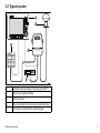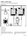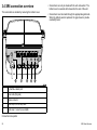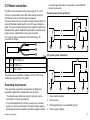
1
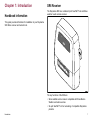
Trademarks and registered trademarks
Autohelm, hsb2, RayTech Navigator, Sail Pilot, SeaTalk, SeaTalkNG, SeaTalkHS and Sportpilot are registered trademarks of Raymarine
UK Limited. RayTalk, Seahawk, Smartpilot, Pathfinder and Raymarine are registered trademarks of Raymarine Holdings Limited.
All other product names are trademarks or registered trademarks of their respective owners.
Fair Use Statement
You may print no more than three copies of this manual for your own use. You may not make any further copies or distribute or use the
manual in any other way including without limitation exploiting the manual commercially or giving or selling copies to third parties.
Copyright ©2010 Raymarine UK Ltd. All rights reserved.
ENGLISH
Document number: 87123-1
Date: 09-2010
Contents
Chapter 1 Introduction ............................................. 7
Handbook information ..................................................... 7
SR6 Receiver ................................................................. 7
Important information ...................................................... 8
5.2 Raymarine technical support...................................... 28
Appendix A Technical specification ....................... 29
Cleaning ........................................................................ 10
Warranty registration....................................................... 10
Chapter 2 Parts and accessories ............................ 11
2.1 Parts supplied........................................................... 12
2.2 Tools Required.......................................................... 13
Chapter 3 Cables and connections......................... 15
3.1 General cabling guidance .......................................... 16
3.2 Typical system .......................................................... 17
3.3 SR6 hub — SeaTalkhs network ................................... 18
3.4 SR6 connection overview .......................................... 20
3.5 Power connection ..................................................... 21
Chapter 4 Installation ............................................... 23
4.1 Location requirement for Sirius receiver...................... 24
4.2 Installation procedure ................................................ 24
4.3 Activate the Sirius receiver ........................................ 26
Chapter 5 Troubleshooting and support ................ 27
5.1 Status LED ............................................................... 28
5
6
SR6 Sirius Receiver
Chapter 1: Introduction
Handbook information
SR6 Receiver
The Raymarine SR6 is a combined 6 port SeaTalkhs hub and Sirius
weather / audio service receiver.
This guide provides information for installation of your Raymarine
SR6 Sirius receiver and network hub.
D11922-1
The key functions of the SR6 are:
• Sirius satellite service receiver compatible with Sirius Marine
Weather and audio services.
• Six port SeaTalkhs hub for networking of compatible Raymarine
products.
Introduction
7
SeaTalkhs
SeaTalkhs is an ethernet based marine network. This high speed
protocol allows compatible equipment to communicate rapidly and
share large amounts of data.
Information shared using the SeaTalkhs network includes:
• Shared cartography (between compatible displays).
• Digital radar data.
Warning: Product grounding
Before applying power to this product, ensure it has
been correctly grounded, in accordance with the
instructions in this guide.
Caution: Power supply protection
• Sonar data.
When installing this product ensure the power source
is adequately protected by means of a suitably-rated
fuse or automatic circuit breaker.
Important information
Caution: Service and maintenance
Warning: Product installation and
operation
This product must be installed and operated in
accordance with the instructions provided. Failure to
do so could result in personal injury, damage to your
boat and/or poor product performance.
Warning: Switch off power supply
Ensure the boat’s power supply is switched OFF
before starting to install this product. Do NOT connect
or disconnect equipment with the power switched on,
unless instructed in this document.
Warning: Potential ignition source
This product is NOT approved for use in
hazardous/flammable atmospheres. Do NOT install in
a hazardous/flammable atmosphere (such as in an
engine room or near fuel tanks).
8
This product contains no user serviceable
components. Please refer all maintenance and repair
to authorized Raymarine dealers. Unauthorized repair
may affect your warranty.
Sirius weather disclaimer
The weather information is subject to service interruptions and may
contain errors or inaccuracies and consequently should not be
relied upon exclusively. You are urged to check alternate weather
information sources prior to making safety related decisions. You
acknowledge and agree that you shall be solely responsible for use
of the information and all decisions taken with respect thereto. By
using this service, you release and waive any claims against Sirius
Satellite Radio Inc., WSI, Navcast Incorporated, and Raymarine
with regard to this service.
If you do not have the subscription agreement, you may view a copy
on the internet at www.sirius.com/marineweather
SR6 Sirius Receiver
IMO and SOLAS
The equipment described within this document is intended for use
on leisure marine boats and workboats not covered by International
Maritime Organization (IMO) and Safety of Life at Sea (SOLAS)
Carriage Regulations.
EMC installation guidelines
Raymarine equipment and accessories conform to the appropriate
Electromagnetic Compatibility (EMC) regulations, to minimize
electromagnetic interference between equipment and minimize the
effect such interference could have on the performance of your
system
Correct installation is required to ensure that EMC performance is
not compromised.
For optimum EMC performance we recommend that wherever
possible:
Note: Where constraints on the installation prevent any of
the above recommendations, always ensure the maximum
possible separation between different items of electrical
equipment, to provide the best conditions for EMC performance
throughout the installation
Suppression ferrites
Raymarine cables may be fitted with suppression ferrites. These
are important for correct EMC performance. If a ferrite has to be
removed for any purpose (e.g. installation or maintenance), it must
be replaced in the original position before the product is used.
Use only ferrites of the correct type, supplied by Raymarine
authorized dealers.
Product disposal
Dispose of this product in accordance with the WEEE Directive.
• Raymarine equipment and cables connected to it are:
– At least 1 m (3 ft) from any equipment transmitting or cables
carrying radio signals e.g. VHF radios, cables and antennas.
In the case of SSB radios, the distance should be increased
to 7 ft (2 m).
– More than 2 m (7 ft) from the path of a radar beam. A radar
beam can normally be assumed to spread 20 degrees above
and below the radiating element.
• The product is supplied from a separate battery from that used
for engine start. This is important to prevent erratic behavior
and data loss which can occur if the engine start does not have
a separate battery.
• Raymarine specified cables are used.
• Cables are not cut or extended, unless doing so is detailed in
the installation manual.
Introduction
The Waste Electrical and Electronic Equipment (WEEE)
Directive requires the recycling of waste electrical and electronic
equipment. Whilst the WEEE Directive does not apply to some
Raymarine products, we support its policy and ask you to be aware
of how to dispose of this product.
Technical accuracy
To the best of our knowledge, the information in this document was
correct at the time it was produced. However, Raymarine cannot
accept liability for any inaccuracies or omissions it may contain. In
addition, our policy of continuous product improvement may change
specifications without notice. As a result, Raymarine cannot accept
liability for any differences between the product and this document.
9
Cleaning
1. Switch off the power to the unit.
2. Wipe the unit with a clean, damp cloth.
3. If necessary, use isopropyl alcohol (IPA) or a mild detergent to
remove grease marks.
Note: Do NOT use abrasive, or acid or ammonia based products.
Warranty registration
To register your Raymarine product ownership, please take a few
minutes to fill out the warranty registration card found in the box, or
visit www.raymarine.com and register on-line.
It is important that you register your product to receive full warranty
benefits. Your unit package includes a bar code label indicating the
serial number of the unit. You should stick this label to the warranty
registration card.
10
SR6 Sirius Receiver
Chapter 2: Parts and accessories
Chapter contents
•
2.1 Parts supplied on page 12
•
2.2 Tools Required on page 13
Parts and accessories
11
2.1 Parts supplied
Each grommet is designed for a specific cable type:
S R6
2 x2
x6
x1
x1
x1
Grommet ID
(letter)
Description
B
1 x Power cable grommet (pre fitted)
A
6 x SeaTalkhs cable grommet.
D
1 x Antenna cable grommet
X
1 x Antenna cable plus one audio cable grommet.
W
1 x Antenna cable plus two audio cable grommet.
C
1 x Single Audio cable grommet
N/A
5 x Blank grommet, fitted when no cable is used.
Additional parts required
x1
1
3
x5
• Sirius antenna. You will need to obtain a suitable antenna. The
recommended antenna is the Shakespeare SRA–40.
• SeaTalkhs cable, required for connection to the Raymarine
multifunction display.
4 x2
D11915-1
1
SR6 Sirius receiver (with 2 m (6.6 ft) power cable attached)
2
2 x #10 stainless steel 3/4 inch self-tapping screws
3
16 x cable entry grommets (see separate table below)
4
2 x 2 m (6.6 ft) audio cable (terminated with 3.5 mm stereo jack
plugs)
12
SR6 Sirius Receiver
2.2 Tools Required
2
1
3
D11908-1
1
Drill
2
7/64” Drill bit
3
Phillips screwdriver
Parts and accessories
13
14
SR6 Sirius Receiver
Chapter 3: Cables and connections
Chapter contents
•
3.1 General cabling guidance on page 16
•
3.2 Typical system on page 17
•
3.3 SR6 hub — SeaTalkhs network on page 18
•
3.4 SR6 connection overview on page 20
•
3.5 Power connection on page 21
Cables and connections
15
3.1 General cabling guidance
Always route data cables as far away as possible from:
• other equipment and cables,
Cable types and length
• high current carrying ac and dc power lines,
It is important to use cables of the appropriate type and length
• Unless otherwise stated use only standard cables of the correct
type, supplied by Raymarine.
• Ensure that any non-Raymarine cables are of the correct quality
and gauge. For example, longer power cable runs may require
larger wire gauges to minimize voltage drop along the run.
• antennae.
Strain relief
Ensure adequate strain relief is provided. Protect connectors from
strain and ensure they will not pull out under extreme sea conditions.
Routing cables
Circuit isolation
Cables must be routed correctly, to maximize performance and
prolong cable life.
Appropriate circuit isolation is required for installations using both
AC and DC current:
• Do NOT bend cables excessively. Wherever possible, ensure a
minimum bend radius of 100 mm.
• Always use isolating transformers or a separate power-inverter
to run PC’s, processors, displays and other sensitive electronic
instruments or devices.
• Always use an isolating transformer with Weather FAX audio
cables.
Minimum bend
200 mm (8 in)
diameter
Minimum bend of cable
100 mm (4 in) radius
• Always use an isolated power supply when using a 3rd party
audio amplifier.
• Always use an RS232/NMEA converter with optical isolation on
the signal lines.
• Protect all cables from physical damage and exposure to heat.
Use trunking or conduit where possible. Do NOT run cables
through bilges or doorways, or close to moving or hot objects.
• Always make sure that PC’s or other sensitive electronic devices
have a dedicated power circuit.
• Secure cables in place using tie-wraps or lacing twine. Coil any
extra cable and tie it out of the way.
Cable shielding
• Where a cable passes through an exposed bulkhead or deckhead,
use a suitable watertight feed-through.
Ensure that all data cables are properly shielded that the cable
shielding is intact (e.g. hasn’t been scraped off by being squeezed
through a tight area).
• Do NOT run cables near to engines or fluorescent lights.
16
SR6 Sirius Receiver
3.2 Typical system
1
2
5
3
4
D11916-1
1
Compatible multifunction display. (Connected using SeaTalkhs)
2
Antenna (not supplied with the SR6)
3
SR6 Sirius Receiver
4
Ship’s audio amplifier (Connected using the supplied audio cable)
5
Power Supply (Connected with the supplied flying lead)
Cables and connections
17
3.3 SR6 hub — SeaTalkhs network
The SeaTalkhs network allows you to connect compatible displays and other digital devices.
Example SeaTalkhs network
1
1
4
2
SeaTalkhs
SeaTalkhs
3
SeaTalkhs
SeaTalkhs
D11950-1
1. Multifunction display
2. SeaTalkhs hub (e.g. SR6)
3. Digital sounder (DSM)
4. Digital radar scanner
• Use a SeaTalkhs network cables to connect the SR6 to your
multifunction display. These have a waterproof connector at one
end.
18
• Use SeaTalkhs patch cables for connections to equipment without
a waterproof connector. (Refer to product documentation for
details).
SR6 Sirius Receiver
SeaTalkhs network cables
Cable
Part number
1.5 m (4.9 ft) SeaTalkhs network cable
E55049
5 m (16.4 ft) SeaTalkhs network cable
E55050
10 m (32.8 ft) SeaTalkhs network cable
E55051
20 m (65.6 ft) SeaTalkhs network cable
E55052
SeaTalkhs patch cables
Cable
Part number
1.5 m (4.9 ft) SeaTalkhs patch cable
E06054
5 m (16.4 ft) SeaTalkhs patch cable
E06055
10 m (32.8 ft)
SeaTalkhs
patch cable
E06056
15 m (49.2 ft)
SeaTalkhs
patch cable
A62136
20 m (65.6 ft) SeaTalkhs patch cable
E06057
Cables and connections
19
3.4 SR6 connection overview
• Connections can only be made with the unit unmounted. The
bottom cover is secured with screws into the rear of the unit.
The connectors are located by removing the bottom cover.
2
1
3
4
• Connections must be made through the appropriate grommets.
When the bottom panel is replaced, the gap closes to provide
a watertight seal.
5
D11917-1
1
6 x SeaTalkhs network ports
2
Power cable (flying lead)
3
Antenna connector
4
Audio output 2, not currently used.
5
Audio output 1, output to your amplifier.
Connection care points:
20
SR6 Sirius Receiver
3.5 Power connection
If a bonded ground system is not possible, a non-bonded RF
ground may be used.
The SR6 can be connected to a DC power supply of 12 or 24 V.
Bonded ground system (preferred)
There is no power switch on the SR6 Sirius weather receiver, it
automatically turns on when the system is powered.
The power connection for your system should be made at either the
output of the battery isolator switch, or at a DC power distribution
panel. The power must be fed directly to the system through its own
dedicated cable system and MUST be protected by a thermal circuit
breaker or fuse, installed close to the power connection.
A 2 m (6.6 ft) cable is hard-wired into the SR6 receiver for
connection as follows:
1
2
3
4
3
4
2
3
D11907-1
1
Red
12/24 V Battery +ve
2
Black
0 V Battery -ve
3
D11709-1
1
RF ground system (alternative)
Drain / ground
This cable may be extended to a distance of 20 m (60 ft) using
suitable wire, gauge AWG 12 or greater.
These grounding requirements are applicable for Raymarine
equipment supplied with a separate drain wire or screen.
• The product power cable drain conductor (screen) must be
connected to a common ground point.
• It is recommended that the common ground point is a bonded
ground, i.e. with the ground point connected to battery negative,
and situated as close as possible to the battery negative terminal.
Cables and connections
1
2
D11710-1
Grounding requirements
1. Power cable to product.
2. Drain (screen).
3. Bonded (preferred) or non-bonded RF ground.
4. Power supply or battery.
21
Implementation
If several items require grounding, they may first be connected
to a single local point (e.g. within a switch panel), with this point
connected via a single, appropriately-rated conductor, to the boat’s
common ground. The preferred minimum requirement for the path
to ground (bonded or non-bonded) is via a flat tinned copper braid,
with a 30 A rating (1/4 inch) or greater. If this is not possible, an
equivalent stranded wire conductor maybe used, rated as follows:
• for runs of <1 m (3 ft), use 6 mm2 (#10 AWG) or greater.
• for runs of >1 m (3 ft), use 8 mm2 (#8 AWG) or greater.
In any grounding system, always keep the length of connecting
braid or wires as short as possible.
Important: Do NOT connect this product to a positively-grounded
power system.
References
• ISO10133/13297
• BMEA code of practice
• NMEA 0400
22
SR6 Sirius Receiver
Chapter 4: Installation
Chapter contents
•
4.1 Location requirement for Sirius receiver on page 24
•
4.2 Installation procedure on page 24
•
4.3 Activate the Sirius receiver on page 26
Installation
23
4.1 Location requirement for Sirius
receiver
4.2 Installation procedure
1. Use a 7/64" drill bit to pilot holes for the mounting points.
The installation location must take into account the following
requirements:
• Install below decks in a dry area.
• Location must be at least 1 m (3 ft.) away from any magnetic
compass.
• Safe from physical damage and excessive vibration.
• Away from any source of heat.
• Away from any potential flammable hazard, such as fuel vapors.
• Allow a minimum 30 cm (6 in) space below the unit to ensure
adequate space for cable bends and connections.
D11912-1
2. Remove the bottom cover. This is secured with 3 screws at the
rear of the unit.
24
SR6 Sirius Receiver
4. Connect the unit to the power supply using the hard wired lead.
5. Replace the bottom panel, taking care with the rubber seal, and
replace the three screws.
6. Secure the SR6 unit in place using the 2 self tapping screws
provided.
D11913-1
After installation you will need to activate your Sirius receiver for use
with the Sirius subscription service.
D11914-1
3. Make the antenna, audio and SeaTalkhs cable connections into
the unit. Pass the cables through the appropriate grommets.
• Connect the audio and antenna cables first. These are below
the network connectors and it is easier to connect the antenna
and audio first.
• Antenna and audio should be passed through the same
grommet. (Use the 1 or 2 hole grommet depending upon the
connections required).
• Use a blanking grommet for any unused connections.
Installation
25
4.3 Activate the Sirius receiver
Before using the Sirius receiver you must activate it for your Sirius
subscription.
You will need to contact Sirius and provide them with the ID
associated with your unit. This can be found:
• on the carton in which the unit was packed,
• on your multifunction display, via the weather application setup
menu.
Contact Sirius with this ID to activate your system.
Sirius support
• Sirius marine weather website: www.sirius.com/marineweather
• Telephone: 1–800–869–5480
26
SR6 Sirius Receiver
Chapter 5: Troubleshooting and support
Chapter contents
•
5.1 Status LED on page 28
•
5.2 Raymarine technical support on page 28
Troubleshooting and support
27
5.1 Status LED
5.2 Raymarine technical support
A 3 color LED provides the Satellite Receiver Status
Raymarine provides a comprehensive customer support service, on
the world wide web, through our worldwide dealer network and by
telephone help line. If you are unable to resolve a problem, please
use any of these facilities to obtain additional help.
LED status
Function
Flashing green
Normal operation
2X flashing amber
No display is connected for the Sirius
output
Web support
3X flashing amber
No Sirius signal / Antenna disconnected
www.raymarine.com
3X flashing red
Antenna short circuit fault
Other flashing red
Receiver failure
This contains Frequently Asked Questions, servicing information,
e-mail access to the Raymarine Technical Support Department and
details of worldwide Raymarine agents.
Please visit the customer support area of our website at:
Network LED
Telephone support
Each SeaTalkhs network port has an LED:
In the USA call:
+1 603 881 5200 extension 2444
LED status
Function
Flashing
SeaTalkhs connected and communicating
In the UK, Europe, the Middle East, or Far East call:
+44 (0)23 9271 4713
Off
No cable connected or no current communication
Product information
If you need to request service, please have the following information
to hand:
• Product name.
• Product identity.
• Serial number.
• Software application version.
You can obtain this product information using the menus within your
product.
28
SR6 Sirius Receiver
Appendix A Technical specification
Nominal supply voltage
12 or 24 Vdc
Operating voltage range
+9 to 32 Vdc
Power / Current
• Power: 8 W
• Typ. current: 0.62 A @ 12 V
Environmental
Installation environment
• Operating temperature: –15 °C to
55 °C (5 °F to 131 °F)
• Storage temperature: – 35 °C to
85 °C (–31 °F to 185 °F)
• Relative humidity: max. 95%
• Water proof to IPX4
Connections
• 6 x SeaTalkhs ports
• Sirius audio out (line level)
• Sirius antenna input
• Power in
Dimensions
W 170 mm (6.7 in) x D 55 mm (2.2 in)
x H 195 mm (7.7 in)
Weight
• 0.30 kg (0.66 lb), excluding
pre-fitted power cable
• 0.70 kg (1.54 lb), including pre-fitted
power cable
Technical specification
29
30
SR6 Sirius Receiver
www.ra ym a rin e .c o m