1
2 Installation cont.
2 Installation cont.
NOTE–MODEL 3000: This thermostat is designed for use with 24 Volt-AC low
voltage single stage gas, oil or electric heating or cooling systems, including
single stage heat pumps and can also be used on 250mv to 750mv millivolt
heating only systems. Do not use this thermostat on applications with voltages
above 30 Volts AC.
NOTE–MODEL 3200: This thermostat is designed for use with 24 Volt-AC low
voltage multi-stage gas, oil or electric heating or cooling systems, including
multi-stage heat pump systems. Do not use this thermostat on applications with
voltages above 30 Volts AC.
Installing Your New Thermostat
NOTE: If installing this thermostat in a new installation, locate the thermostat 4
to 5 feet above the floor in accordance with applicable building codes. Install the
thermostat in a location that provides good airflow characteristics and avoid areas
behind doors, near corners, air vents, direct sunlight or heat generating devices.
Installation in these areas could impact thermostat performance. Wiring must
conform to all building codes and ordinances as required by local and national
code authorities having jurisdiction.
1.
2.
3.
4.
5.
6.
7.
8.
9.
10.
11.
12.
13.
14.
15.
16.
17.
Turn off power to the air conditioning or heating system prior to installing thermostat.
Place system switch on front of thermostat to OFF position.
Place fan control switch on front of thermostat to AUTO position.
Remove front of thermostat body from sub-base by pressing release latch.
Place the thermostat sub-base against wall in the desired thermostat location.
Guide thermostat wires through hole in sub-base. Continue to hold against wall.
Mark placement of mounting holes and drill using a 3/16" drill bit.
Gently tap supplied plastic anchors into the holes in the wall.
Place the thermostat sub-base against the wall in the desired location, making
sure the mounting holes are aligned and the thermostat wires are inserted
through opening in sub-base.
Fasten sub-base to wall using supplied screws into the plastic wall anchors.
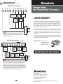
Connect wires to quick wiring terminal block as appropriate using the new
terminal designations. See Section 7.
Make sure all of the wire connections are secure and are not touching any other
terminal to prevent electrical shorts and potential damage to the thermostat.
Turn the front thermostat body over, exposing the rear view of the circuit board.
Locate the internal ˚F / ˚C switch on the circuit board. Using your fingers, flip
the switch toward the preferred temperature ˚F / ˚C scale.
Locate the internal fan option switch, HG (Gas) / HE (Elec) on the circuit board.
This switch controls the heating system fan delay. Select gas for gas or oil fired
systems. This will allow the furnace to run for a few seconds before initiating
the fan. Select electric for systems with electric furnace elements that require
the fan to come on immediately. Using your finger, flip the switch toward the
HG (Gas) or HE (Elec).
Locate the internal NORM / HP switch on the circuit board. This switch
configures the thermostat for conventional (NORM) heating and cooling systems
or heat pump (HP) systems. Using your fingers, flip the switch toward the
NORM or HP.
MODEL 3200 ONLY: Locate the auxiliary heat option switch, AE-AG, on the
circuit board. For electric auxiliary heat units, the switch should be set to the
AE position. For units with gas or oil auxiliary heat, move the switch to the AG
position. This will lock out the compressor stage 1 minute after a second stage
heat call for maximum efficiency.
2
18. Attach front body of thermostat to sub-base of thermostat, being careful
to align the terminal pins on the front body with the terminal block on
the sub-base.
19. Open front thermostat door and open battery compartment door.
20. Install two new "AA" alkaline batteries. Locate the positive (+) ends of the
batteries and match them with the positive (+) terminals located in the battery
compartment. Close battery compartment.
21. Restore system power so you can test installation.
NOTE: If batteries were installed prior to accomplishing steps 14 through 16,
you will need to reset the thermostat to register thermostat switch configurations
prior to programming any user settings. Gently press the RESET button on the
front of the thermostat using a paper clip or a small pencil tip.
NOTE–MODEL 3200: If the thermostat is
configured for a conventional system and the
system switch is in the EM HEAT position, the
unit will still function in a conventional 2 stage
HEAT mode, but the display will flash
NO EM HEAT SET.
3 Testing Your New Thermostat
WARNING! Read BEFORE Testing
• Do not short (or jumper) across terminals on the gas valve or at the heating or
cooling system control board to test the thermostat installation. This could
damage the thermostat and void the warranty.
• Do not select COOL mode if the outside temperature is below 50˚ F (10˚ C). This
could damage the controlled cooling system and may cause personal injury.
• This thermostat includes an automatic compressor protection feature to avoid
potential damage to the cooling system from short cycling. This thermostat
automatically provides a 5-minute delay after turning off the cooling or heating
system output to protect the compressor.
NOTE: Test your thermostat prior to programming any user settings. Pressing the
RESET button will erase any user entries previously programmed and return them
to their default values.
1. Place the system switch in the HEAT position.
2. Press the button on the keypad until the set point temperature setting is a
minimum of 3 degrees higher than the current room temperature. The heating
system should start within several seconds. The fan may not turn on immediately
due to the heating system built-in fan delay.
3. Place the system switch in the OFF position. The heating system should stop
within several seconds on conventional heating or cooling systems. On heat
pump systems, you must wait 5 minutes for the automatic compressor short
cycle protection period to expire, or press the RESET button to bypass this
feature for initial testing purposes. Pressing the RESET button will erase any
user program settings.
4. Place the system switch in the COOL position.
5. Press the button on the keypad until the set point temperature is a minimum
of 3 degrees lower than the current room temperature.
3