1
Using your
http://www.napcosecurity.com/
iBridge® IBR-ITAB Security System
© NAPCO 2013
OI372A 03/13
1
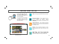
INTRODUCTION
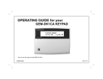
The IBR-ITAB iBridge® Touch
Screen Tablet Keypad is a "smart"
user-friendly, interactive menu-driven ZWave enabled tablet keypad designed
for your Napco control panel. Its interactive touch screen will not only display
the status of your system, but will also
give you step-by-step instructions to
guide you through all operations.
This booklet contains important
information about the operation of your
system with the IBR-ITAB keypad; read
it carefully and keep it handy for future
reference. Check the Glossary for terms
that may be unfamiliar to you.
You'll probably find subjects or
screens mentioned in this booklet that
do not apply to your system. Napco keypads and control panels have such a
wide variety of features that few security
systems, if any, will ever need them all.
Your alarm professional has chosen
appropriate features for your particular
needs.
Regardless of how your system has
been configured, rest assured that it has
been carefully designed and engineered
to the highest industry standards. To
assure optimum safety and security,
familiarize yourself with this equipment.
Periodically check its condition and state
of readiness by testing it at least once a
week in both the ac/battery and batteryonly modes (ask your alarm professional
how to make these tests).
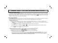
IMPORTANT - TEST YOUR SYSTEM WEEKLY
Test your sounding device and backup battery
Test your central station communicator
(These tests should only be performed on weekends or at a time
(Activate Dialer Test programmed? YES NO)
designated by your alarm company.)
1. Notify your Central Station of the impending test.
1. While disarmed, tap Security, Other Options, Keypad Mode, R.
2. Answer NO (tap Q) until "ACTIVATE SIREN TEST" appears in the 2. While disarmed, enter your User Code and tap R.
3. Answer NO (tap Q) until "ACTIVATE DIALER TEST" appears in
window.
3. Tap YES (P) to execute the test. The alarm will sound for about
the window.
4. Tap YES (P) to send a test code to the central station.
two seconds.
• If the alarm does not sound, call for service.
• If the test is not successful, "COMM FAIL E03-00 SERVICE" will
display, indicating a communication failure. Call for service.
• If the battery is low, "LOW BATTERY E02-00 SERVICE" will appear in
the display indicating a low battery condition. Allow 24 hours for the
Note: Any subsequent successful transmission will clear a "Failure to
battery to recharge. If the trouble continues, call for service.
Communicate" system trouble.
2
T AB L E O F C O N T E N T S
Section
Page
IBR-ITAB HARDWARE CONTROLS & INDICATORS ...........................5
GETTING STARTED ..............................................................................6
USING THE TOUCH SCREEN (AND BACK / POWER BUTTON) ........7
HOME SCREEN ICONS ........................................................................8
ENTER YOUR SECURITY SYSTEM .....................................................9
"K SERIES" KEYPAD MODE: CONTROLS & INDICATORS .............10
"CLASSIC" KEYPAD MODE: CONTROLS & INDICATORS...............12
ARMING AWAY: SETTING THE ALARM WHEN LEAVING ...............14
ARMING STAY: PROTECTING YOURSELF AT HOME ....................16
EASY EXIT / EMERGENCY BUTTONS...............................................17
DISARMING (TURNING OFF THE ALARM) WHEN RETURNING .....18
ARMING "NIGHT": PROTECTING YOURSELF WHEN SLEEPING ..19
BYPASSING ZONES ...........................................................................20
FIRE PROTECTION .............................................................................22
FUNCTION MENU ...............................................................................26
CENTRAL-STATION MONITORING ....................................................31
ADVANCED FEATURES .....................................................................32
PROGRAMMING USER CODES .........................................................33
ENTER ZONE DESCRIPTIONS -- "CELL PHONE STYLE" .......... 35-36
KEYPAD MESSAGES ..........................................................................38
USING THE ONSCREEN KEYBOARD ................................................41
USER SETTINGS MENU .....................................................................44
GLOSSARY ..........................................................................................56
SYSTEM TROUBLE ERROR CODES .................................................59
TROUBLESHOOTING .........................................................................64
TO SILENCE AN ALARM, ENTER YOUR
CODE, AND TAP U.
FOR SERVICE, CALL: ____________________
CENTRAL STATION: _____________________
EXIT DELAY: ___________________________
ENTRY DELAY: _________________________
FIRE ALARM SOUND*:
____________________________________
BURGLAR ALARM SOUND*:
____________________________________
KEYPAD FIRE ENABLED?
YES NO
KEYPAD PANIC ENABLED?
YES NO
KEYPAD AUX. ENABLED?
YES NO
*FIRE HAS PRIORITY OVER BURGLARY.
3
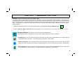
INTRODUCTION
THANK YOU FOR CHOOSING NAPCO
This guide will introduce you to the features of your new IBRITAB iBridge® tablet keypad. For assistance, please go to
napcosecurity.com. Note: Screen images, icons and instructions shown in this guide may vary depending on the firmware
version installed in your IBR-ITAB.
IMPORTANT CUSTOMER INFORMATION
Please be advised that the various applications and services
available through this iBridge tablet device are provided by various device, operating system, software and application developers (e.g., Google™, Motorola, Microsoft®, Palm®, etc.). If you
use, link to or download a service or software application such
as a non-Napco location-based GPS type service, chat room,
marketplace or social network from this device, you should
carefully review the terms of service or application. If you use
any of these non-Napco services or applications, personal infor-
mation you submit may be read, collected, or used by the service or application provider and/or other users of those services.
Napco is not responsible for your use of those applications or
for the information you choose to share with others. Specific
terms and conditions, privacy polices and terms of use apply to
those non-Napco applications and services. Please carefully
review all conditions and terms applicable to those services and
software applications for all privacy policies, risks or waivers.
Your Napco Limited Warrantee and other terms and conditions
govern your use of all Napco wireless products and services.
Before charging, assembling or using your IBR-ITAB iBridge
tablet keypad device for the first time, please read and understand the important safety and legal information packaged with
your device.
Caution: The rear of the IBR-ITAB contains a strong magnetic
field that can interfere with pacemakers, defibrillators and other
electronic devices.
IMPORTANT NOTE
Although the instructions in this guide are depicted using the GEM-K1CA "K Series" keypad buttons, this guide can also be
used with the "classic" GEM-RP1CAe2 keypad. If your system uses the "classic" GEM-RP1CAe2 keypad, the "classic" INTERIOR, INSTANT, FUNCTION and ON/OFF buttons can be used in place of the "K Series" model STAY, AWAY, MENU and
ENTER buttons respectively. Refer to the User Guide that came with your wired keypad for more information.
4
I B R - I T AB H A R D W AR E C O N T R O L S & I N D I C AT O R S
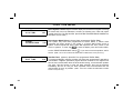
– (Volume Down): Press to decrease the
loudness of the IBR-ITAB sounds.
+ (Volume Up): Press to increase the loudness of the IBR-ITAB sounds.
M (Menu): Press to display a menu of selections for most screens.
(Home): Press and hold to go to the Touch
Screen Calibration screen (see page 47).
USB Socket: Standard USB socket
for thumb drives, portable hard
drives, memory sticks, etc. For data
transfer only (NOT for charging).
Microphone: Integral high sensitivity,
voice input.
Back / Power Button: Press to turn on your IBR-ITAB. When up
and running, press to return to the previous screen. Lights red when
charging, and green when fully charged (but still attached to the
charger).
Mini-B USB Socket: (Do not use).
Three options appear when the Back / Power Button is pressed and held down
for several seconds:
Screen Lock Turns the IBR-ITAB screen off; the IBR-ITAB Napco Security
Application still runs in the background; press any button on the IBR-ITAB
and the Home Screen appears.
Reboot Restarts the IBR-ITAB; the IBR-ITAB Napco Security Application
turns off and automatically starts again.
microSD Card Slot: A slot for a secure digital microSD flash memory
card. Supports card capacities of
up to eight gigabytes, for of added
storage. Note: The "microSD" card
format is also called "TransFlash".
Power Off After a confirmation popup. exits the IBR-ITAB Napco Security
Application, and turns the IBR-ITAB off. To restart, wait 15 seconds, then
press and hold the Back / Power Button until the screen displays startup
text, indicating the IBR-ITAB has turned on and will begin the startup
process.
5
GETTING STARTED
CHARGE YOUR IBR-ITAB
The model IBR-ITAB iBridge® wireless tablet keypad
contains a rechargeable battery that must be charged at
its wall-mounted charging station, or at an IBRITABSTAND desk-mounted charging station.
Caution: Use ONLY the charger that came with your
IBR-ITAB when charging. Do NOT attempt to connect a
charger to the USB port. The USB port is used for data
transfer only, NOT for charging.
Place the IBR-ITAB into the wall-mounted charging station. If using the IBR-ITABSTAND desk mounted charging station, be sure to plug the other end of the charging
station into a standard electrical outlet. While the battery
is charging, the Back / Power Button charging indicator
lights red.
Caution: Before assembling, charging, or using your device for the first time, please read the important legal and
safety information packaged with your IBR-ITAB. Any
attempt to remove or replace your battery may damage
the product. The battery should only be replaced by a
Napco-approved service facility.
TURNING ON YOUR IBR-ITAB
Press and hold the Back / Power Button until
the screen displays startup text, indicating the
IBR-ITAB has turned on and will begin the
startup process. After a short time a popup
appears; tap "Napco RCM Application" to
continue.
Note: To automatically start the Napco RCM Application, check the Use by default for this action checkbox
before tapping the "Napco RCM Application" selection.
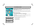
After a few seconds, the IBR-ITAB Napco Security Application Home Screen appears. From this screen, tap any
of several buttons, including:
Security: Tap to display the status of your Napco
alarm system. Allows the control of all system
operations, just like a standard wired keypad.
Video: (optional) Tap to discover and view the
camera transmissions in your system.
Automation: (optional) Tap to control the home
automation system components, including lighting
and other devices.
Climate: (optional) Tap to control the home automation thermostats and other climate control devices.
6
U S I N G T H E T O U C H S C R E E N ( AN D B AC K / P O W E R B U T T O N )
Navigation through the IBR-ITAB
When the IBR-ITAB is first powered, the Home Screen is the
first screen displayed. You can navigate through various submenus by simply using your finger to touch through the icons
and menus as needed. The IBR-ITAB responds differently depending on how the screen is touched:
• Touch: To chose an icon, or click a button or menu selection, touch or "tap" it with your finger.
• Drag: To scroll or move slowly, touch and hold to select a
menu item, then drag your finger up and down the touch
screen to scroll through the menu selections.
"Touch": Chose an icon or button by touching or "tapping"
• Hold Down: Certain icons have two functions depending
on whether they are tapped or pressed and held down for
3 seconds.
Using the Back / Power Button
• Home: Press the Back / Power Button repeatedly to return to the Home Screen.
• Back: Press the Back / Power Button to return to the previous screen.
"Drag": Touch and hold, then drag up and down to scroll
7
HOME SCREEN ICONS
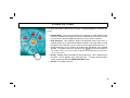
The "Home Screen" may contain other touchable icons, including:
SECURITY: This icon is your
gateway to your alarm system.
From here you can arm, disarm,
bypass and control all system
operations.
may prevent arming (see SYSTEM
TROUBLE ERROR CODES). If you
are unable to clear the trouble to
allow the system to be armed,
call for service immediately.
VIDEO: (optional) Tap to discover and view the camera transmissions in your system.
EMERGENCY Buttons: Used
to signal a Fire, Police or Auxiliary emergency.
AUTOMATION: (optional) Tap
to control the Z-Wave home
automation system components,
including lighting and other devices.
CLIMATE: (optional) Tap to control the Z-Wave home automation
thermostats and other climate
control devices.
LOCKING DEVICES: (optional)
Tap to access the Z-Wave door
locking devices in your system.
TROUBLES: Appears if a problem occurs in the system that
8
USER SETTINGS: Tap to access the screens to allow
changes to the way your IBRITAB operates (see USER SETTINGS MENU).
HELP: On-screen instructions
for Z-Wave functions.
BROWSER: Tap to open the
IBR-ITAB web browser, allowing
access to the Internet.
HOME: Tap to return directly to
the Home Screen.
SIGNAL: Displays the wireless
signal power. The indicator displays 3 bars maximum; the more
bars lit, the stronger the wireless
signal. A red "X" appears when
the device is not connected.
BATTERY CHARGE STATUS:
Displays the condition of the integral battery. When charging, the
blue icon appears; when fully
charged, the full green icon appears. When the battery is approximately half-drained, the yellow icon appears. When battery
is almost depleted, the red warning icon appears (reconnect to
charging station immediately).
ENTER YOUR SECURITY SYSTEM
Tap to arm
"Away" when
leaving (page 14)
Tap to arm "Night"
when sleeping
(page 19)
Tap to selectively
bypass zones
(page 20)
Tap for other options:
• Keypad Mode
• Zone Directory
• Events
• Dealer Servicing
Information
(page 21)
Tap to arm
"Stay" to protect
yourself at home
(page 16)
Tap to disarm
the system
(icon active only
when armed)
(page 18)
9
" K S E R I E S " K E Y P AD M O D E : C O N T R O L S & I N D I C AT O R S
2
1
3
14
SYSTEM READY 1
10/16/18 09:40AM
13
6
12
4
11
5
10
7
10
8
9
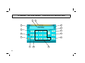
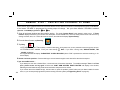
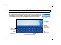
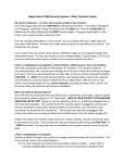
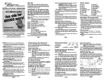
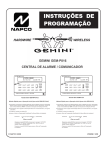
" K S E R I E S " K E Y P AD M O D E : C O N T R O L S & I N D I C AT O R S
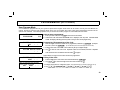
1. Banner: Displays system status
messages, zone descriptions,
etc.
2. Keypad Window: Displays
system status messages, zone
descriptions, etc.
3. BACK Button: Tap to return to
the previously selected screen.
4. EMERGENCY Buttons: Used
to signal a Fire, Police or
Au xil iary em er gen c y (f or
example, a medical emergency).
5. USER SETTINGS:
Tap to
access the screens to allow
changes to the way your IBRITAB operates (see USER
SETTINGS MENU).
6. MENU Button:
Selects
available system functions as
displayed in the window. The
selected function is executed by
tapping the U button.
7. B Y P AS S B u t t o n :
(1)
Deactivates selected zones from
the system. (2) Unbypasses a
bypassed zone (GEMP816/1632/1664/3200/9600/
X255 panels only).
8. RESET Button:
(1) Resets
various s ystem troubles,
displays, etc. (see text). (2)
Resets residential smoke
detectors.
9. Numerical Keys (1-9, 0): Used
to enter codes, zone numbers,
etc.
10. AREA Button (G): Selects
other areas (see Manager's
Mode on page 15).
11. AWAY Button: (1) Arms all
zones in the system, with
display indicating the exit time
remaining. (2) Scrolls window
display backward (PRIOR). (3)
Answers "No" to questions in
the window display.
12. STAY Button: (1) Bypasses all
Interior Zones simultaneously
("STAY Mode") to allow free
movement within the premises.
Hold down P when the
system is armed in "STAY
Mode" to cancel entry delay on
Exit/Entry zones, causing an
instant alarm upon violation. (2)
Scrolls the window display
forward (NEXT). (3) Answers
"Yes" to questions in the window
display.
13. ENTER Button: Input entry
key. Causes the entered code
or selected function to be
executed.
14. HOME: Tap to return directly to
the Home Screen.
11
" C L AS S I C " K E Y P AD M O D E : C O N T R O L S & I N D I C AT O R S
2
1
3
14
4
13
5
12
6
11
10
7
8
12
9
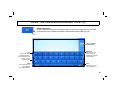
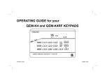
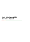
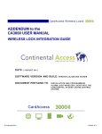
" C L AS S I C " K E Y P AD M O D E : C O N T R O L S & I N D I C AT O R S
1. Banner: Displays system status
messages, zone descriptions,
etc.
to signal a Fire, Police or
A ux i l ia ry e m er genc y ( f o r
example, a medical emergency).
2. Keypad Window: Displays
system status messages, zone
descriptions, etc.
7. USER SETTINGS:
Tap to
access the screens to allow
changes to the way your IBRITAB operates (see USER
SETTINGS MENU).
3. BACK Button: Tap to return to
the previously selected screen.
4. FUNCTION Button:
Selects
available system functions as
displayed in the window. The
selected function is executed by
tapping the J button.
5. B Y P AS S B u t t o n :
(1)
Deactivates selected zones from
the system. (2) Unbypasses a
bypassed zone (GEMP3200/9600/X255 panels only).
6. EMERGENCY Buttons: Used
8. RESET Button:
(1) Resets
various s ystem troubles,
displays, etc. (see text). (2)
Resets residential smoke
detectors.
9. Numerical Keys (1-9, 0): Used
to enter codes, zone numbers,
etc.
10. AREA Button (G): Selects
other areas (see Manager's
Mode on page 15).
entry delay on Exit/Entry Zones,
causing an instant alarm upon
violation. (2) Scrolls window
display backward (PRIOR). (3)
Answers "NO" to questions in
the window display.
12. I N T E R I O R
Button: (1)
Bypasses all Interior Zones
simultaneously to allow free
movement within the premises.
(2) Scrolls the window display
forward (NEXT). (3) Answers
"YES" to questions in the
window display.
13. ON/OFF Button: Input entry
key. Causes the entered code
or selected function to be
executed.
14. HOME: Tap to return directly to
the Home Screen.
11. INSTANT Button: (1) Cancels
13
A R M I N G " AW A Y " : S E T T I N G T H E AL AR M W H E N L E A V I N G
If the feature "EZ-ARM" is programmed, the arming steps will change. Ask your alarm installer if EZ-ARM is enabled.
(Optional - Is EZ-ARM programmed?
YES NO)
1 Close all perimeter windows and doors before arming.
The words "System Ready" must appear in order to arm. If "Zones
Faulted" displays followed by the number and description of each faulted zone, then note each problem zone and secure it by
closing a window, door, etc. When all zones are secure, the window will display "System Ready".
2 From the Home Screen, tap Security.
3 Tap Away.
• If EZ-ARM is enabled: The Exit Delay countdown takes place, during which time you are permitted to leave through the exit door.
• If EZ-ARM is NOT enabled: Enter your code and tap U. Note: If you enter a wrong code, "INVALID ENTRY, TRY
AGAIN" will display.
The Keypad Window will display "PLEASE EXIT IN XXX SECONDS" (where "XXX" represents the exit time remaining, in 10second steps).
4 Leave the premises.
Leave through the exit door before the exit time expires.
If you are unable to arm…
If you attempt to arm with a faulted Zone, a 3-second tone will sound at the tablet. The audible message "There is a Zone
open, please secure and try again" and the text "CAN'T ARM SYSTEM, ZONE FAULTED" will display in the window,
indicating that the faulted zone(s) must be secured before the panel can be armed.
14
If you cannot secure the faulted zone(s), cannot locate or repair the problem yourself, either call your alarm installer for assistance, or you can temporarily bypass the problem zone(s) from the system (see Bypassing Zones on page 20).
A R M I N G " AW A Y " : S E T T I N G T H E AL AR M W H E N L E A V I N G
Arming with a System Trouble
If you attempt to arm with a "SYSTEM TROUBLE" display alternating with an indicated trouble code (e.g. "E02-00" (low battery);
see SYSTEM TROUBLE ERROR CODES), a 3-second tone will sound at the keypad. The window will display "CAN'T ARM
SYSTEM, PRESS RESET KEY". If you cannot correct the problem immediately, tapping C will enable you to arm in this
condition. Be sure to call for service as soon as possible.
Area Arming (Optional)
Some systems may be divided, or partitioned, into smaller independent subsystems, which are referred to as Areas. In a system
that has been partitioned into multiple areas, one or more area may be armed while others remain disarmed.
Manager's Mode (Optional)
The Manager's Mode allows the user to arm / disarm other areas in a partitioned system. To arm/disarm a different area:
1. While disarmed, tap Security, Other Options, Keypad Mode. Tap the numerical key representing the other area
number.
2. Tap G followed by U. The keypad will now provide status and control of that area.
3. Enter your User Code followed by Q (use D for "Classic" keypad configurations) to arm or disarm the area.
4. Tap G followed by U to return to the home area.
Global Arming (Optional) (Available only with the GEM-P1632/1664/3200/9600/X255 panels)
To arm all areas simultaneously, tap 9, G and enter your code followed by U.
To disarm all areas simultaneously, tap 0, G and enter your code followed by U.
• The User Code must be valid in all area(s).
• If any zone is not secured, the keypad will display "CAN'T ARM SYSTEM, AREA X IN TROUBLE", where X indicates
the number of the Area in trouble. All faulted zones in the respective area(s) must be secured or bypassed. Note: If a
system trouble is indicated, the system cannot be armed using this method.
15
A R M I N G " S T A Y " : P R O T E C T I N G Y O U R S E L F AT H O M E
Interior Zones, when bypassed, allow free movement within the home while the protection of armed perimeter zones is maintained.
If the feature "EZ-ARM" is programmed, the arming steps will change. Ask your alarm installer if EZ-ARM is enabled.
(Optional - Is EZ-ARM programmed?
YES NO)
1 Close all perimeter windows and doors before arming.
The words "System Ready" must appear in order to arm. If "Zones
Faulted" displays followed by the number and description of each faulted zone, then note each problem zone and secure it by
closing a window, door, etc. When all zones are secure, the window will display "System Ready".
2 From the Home Screen, tap Security.
3 Tap Stay.
• If EZ-ARM is enabled: The Exit Delay countdown takes place, during which time you are permitted to leave through the exit door.
• If EZ-ARM is NOT enabled: Enter your code and tap U. Note: If you enter a wrong code, "INVALID ENTRY, TRY
AGAIN" will display.
The Keypad Window will display "PLEASE EXIT IN XXX SECONDS" (where "XXX" represents the exit time remaining, in 10second steps).
4 Remain inside the premises.
Persons wishing to exit can leave through the exit door before the exit time expires.
If you are unable to arm…
If you attempt to arm with a faulted Zone, a 3-second tone will sound at the tablet. The audible message "There is a Zone
open, please secure and try again" and the text "CAN'T ARM SYSTEM, ZONE FAULTED" will display in the window,
indicating that the faulted zone(s) must be secured before the panel can be armed.
16
If you cannot secure the faulted zone(s), cannot locate or repair the problem yourself, either call your alarm installer for assistance, or you can temporarily bypass the problem zone(s) from the system (see Bypassing Zones on page 20).
E AS Y E X I T / E M E R G E N C Y B U T T O N S
Easy Exit (Optional - Easy Exit programmed? YES NO)
Your system may have been programmed for Easy Exit, which allows a user to exit the premises while the system is armed STAY. By
activating Easy Exit while the system is armed STAY, the Exit Delay countdown will take place, during which time you are permitted to
leave through the exit door. The Easy Exit Delay time will be identical to the Exit Delay time the system gives you each time it is armed
STAY. This will allow, for example, an early morning commuter to exit the house, without having to disarm and rearm the system,
awaking the family.
• With the system armed STAY, open the keypad screen by pressing and holding the Disarm button.
• At the keypad, tap U to activate Easy Exit on your system.
(GEM-P3200/9600/X255 V20 or greater, GEM-P816/P1632/P1664 V9A or greater)
Emergency Buttons (Only available if programmed with the User Settings button)
The Emergency Buttons, if programmed, are always active, whether the system is armed or disarmed.
• Fire Emergency: From the Home Screen, tap the "E" button, then tap the button marked "Fire" (shown at left) to alert the
central station of a fire emergency. *(Is Fire Emergency programmed? YES NO)
• Auxiliary Emergency: From the Home Screen, tap the "E" button, then tap "Aux." (shown at left) to alert the central
station of an auxiliary emergency (for example, a medical emergency). *(Is Aux. Emergency programmed? YES NO)
• Police Emergency: From the Home Screen, tap the "E" button, then tap the button marked "Police" (shown at left) to alert
the central station of a police emergency. *(Is Police Emergency programmed? YES NO)
17
D I S AR M I N G ( T U R N I N G O F F T H E AL AR M ) W H E N R E T U R N I N G
Disarming the System
1 Enter your premises through the Entry/Exit door. The keypad will sound a steady tone to remind you to disarm the system
before your Entry Delay time expires. The keypad automatically appears.
U. The Keypad Window will read "System Ready", indicating that the system has been
2 Enter your User Code and tap
disarmed. If you enter an invalid code, the keypad will beep 4 times, signifying an error. Re-enter your code immediately.
10 seconds before Entry Delay expires, the keypad will emit a pulsing warning tone.
Alarm Indication / Silencing an Alarm
If "ALARM" is displayed, an alarm occurred while you were out. Proceed with caution! If you suspect that an intruder may still be on the
premises, leave immediately and call authorities from a neighbor's telephone.
To silence an audible alarm:
1 At the keypad screen, enter your code and tap U. After the system is disarmed, the window will continue to display
"ALARM" followed by the zone(s) violated.
2 To reset the display, note the zones violated, then tap C.
Ambush (Optional) Your Ambush Code Type is: TYPE 1 (Prefix) TYPE 2 (Unique)
My Ambush Code is ___________________
If an intruder forces you to disarm your system, enter your Ambush Code and tap U.
There are two types of Ambush Codes: (1) A 2-
digit code (prefix) entered just prior to your normal User Code and (2) A separate and unique User Code.
• Example Type 1 (Prefix): If your User Code is 1234 and your Ambush Code is 99, tap 991234U.
• Example Type 2 (Unique): If your User Code is 1234 and your Ambush Code is 8899, tap 8899U
18
Using your Ambush Code will send a silent alarm to the central station. The window will display "SYSTEM READY" as if the system
were normally disarmed. There will be no indication that a silent alarm has been sent.
ARMING "NIGHT": PROTECTING YOURSELF WHEN SLEEPING
Night Mode: Instant Protection
When retiring for the evening, after all family members are home, you can cancel the entry delay on the
Entry Zone(s) and arm the system in "Night Mode" to allow for "Instant Protection". When armed in Night
Mode, opening any entry door will cause an immediate alarm.
When arming with instant Night Mode protection, the exit delay will remain in effect, allowing exiting of the
premises just after arming. While armed, the window will display "SYSTEM ARMED" ("SYSTEM ARMED
I" will display with the GEM-P3200/9600/X255 control panels) and the red colored Banner will read
"Night" to indicate instant protection.
But once armed with instant Night Mode, opening any entry door will cause an immediate alarm.
Tap Night.
• If EZ-ARM is enabled: The Exit Delay countdown takes place, during which time you are
permitted to leave through the exit door.
• If EZ-ARM is NOT enabled: Enter your code and tap U. Note: If you enter a wrong code,
"INVALID ENTRY, TRY AGAIN" will display.
The Keypad Window will display "EXIT TIME XXX", "PLEASE LEAVE NOW" (where "XXX" represents
the exit time remaining, in 10-second steps).
19
B Y P AS S I N G Z O N E S
If you attempt to arm with a faulted Zone, a 3-second tone will sound at the tablet. The
audible message "There is a Zone open, please secure and try again" and the text
"ZONES FAULTED" will display in the window, indicating that the faulted zone(s) must
be secured before the panel can be armed.
If you cannot locate or repair the problem yourself, call your alarm installer for assistance.
If you cannot get immediate help, bypass the problem zone(s) from the system as follows:
Selectively Bypassing Zones
From the Home Screen, tap Security, then tap Bypass Zones.
Bypass the problem zone(s) from the system by tapping B, then the zone number
(or vice versa).
Note: Bypassed zones are unprotected. If armed with zones bypassed, be sure to
have the system checked and corrected as soon as possible.
CAN’T ARM SYS TEM
ZONE S FAULTED
With the problem zone(s) bypassed from the system, you can:
• Arm "Away" (see page 14)
• Arm "Stay" (see page 16)
ZONES FAULTED
BYPASS
20
BYPASSED
• Arm "Night" (see page 19)
OTHER OPTIONS
Your IBR-ITAB includes a wide variety of features. Tap Other Options to access the following:
• Keypad Mode: Tap to open the keypad screen, allowing your IBR-ITAB to behave
just like a standard wired keypad, but with the added benefit of the Banner at the
top of the screen, providing additional guidance to control system conditions.
• Zone Directory: Tap to display a listing of all protected zones in the Area. If
needed, tap the up or down arrow buttons (located on the right side) to scroll
through the zone directory (required for GEM-P816/1632/1664/3200/9600/X255 panels). If
faulted zones exist in your system, the faulted zone will appear in the Keypad
Window. To bypass a zone from the system, tap B, then the zone number (or
vice versa). (Note: This function available with GEM-P1632 and GEM-P1664 control panel firmware version 9a or later).
• Events: Displays most recent alarm events (history log). Line 1 displays event
and date. Line 2 displays time, area and zone. To check previous alarm
events, scroll back using the PRIOR (INSTANT) button.
• Service: For installer use only.
21
FIRE PROTECTION
(Applicable only where local ordinance permits use of this alarm control panel for fire protection.)
FIRE
FIRE ALARM
Fire-Zone Alarm*
If a fire is detected, "FIRE ALARM" will be displayed and the keypad sounder will pulse. In
addition, the "System Trouble" icon will flash.
1. If a fire is in progress, evacuate the premises immediately! If necessary, call the Fire
Department from an outside phone.
2. Tap the C button to silence the keypad sounder.
3. If there is no evidence of a fire, enter your User Code and tap U to turn off the alarm.
4. Check smoke detector(s). If a smoke detector tripped, its red alarm indicator light will
be on.
After the alarm condition is corrected (thermostat cooled down; smoke cleared from
detector; etc.), tapping C again will reset the keypad within about 10 seconds.
NOTE: When the Fire Zone is reset, the FIRE icon on the left side of the display will go out.
If the FIRE icon is still displayed, the fire zone has not been properly reset. If you cannot
clear this condition by tapping C, call for service.
FIRE TROUBLE
Fire-Zone Trouble*
1. If a problem in the fire-circuit is detected, "FIRE TROUBLE" and the Zone number will
2.
22
*Exact messages and behavior varies depending on control panel.
display and the sounder will pulse to signal a malfunction. The "System Trouble" icon
will flash, and the audible message "System has detected trouble condition" will
sound.
Tap C to silence the sounder. Call for service immediately!
FIRE PROTECTION
Preparing a Fire Escape Plan
Even with the most advanced fire alarm
system, adequate protection requires an
escape plan.
To prepare your plan, draw floor plans of
your building. (Space is provided on the
next page). Show two exits - a front or
back door and a window from each room.
(Make sure the window works. You may
need a special fire-escape ladder if the
window is high up). Write down your
outside meeting place.
Family Rehearsal.
Rehearse each of the following activities:
1. Everyone in his room with the doors
closed.
2. One person sounds the alarm.
3. Each person tests his door.
4. Pretend the door is hot and use the
alternate escape exit.
5. Everyone meets outdoors at the
assigned spot.
Important! - Read Carefully
Discuss these escape procedures with all
those who use the building:
1. In a residence, sleep with the bedroom
door closed. A closed door will hold
back deadly smoke while you escape.
2. When the fire alarm signals, escape
quickly. Do not stop to pack.
3. Test the door. If it is hot, use your
alternate route through the window. If
the door is cool, brace your shoulder
against it and open it cautiously. Be
ready to slam the door if smoke or
heat rushes in. Crawl through smoke,
holding your breath. Close the doors
again on leaving to help prevent the
fire from spreading.
4. Go to your specific outdoor meeting
place so you can see that everyone is
safe.
5. Assign someone to make sure nobody
returns to the burning building.
6. Call the Fire Department from a
neighbor's telephone.
Would You Like More Safety Information?
For more information on home fire detection, burn safety, and home fire safety,
write to the National Fire Protection Association, Public Affairs Dept. 05A,
Batterymarch Plaza, Quincy, MA 02269.
23
FIRE PROTECTION
Floorplan
Draw a plan of your premises in the space provided below.
Floorplan
24
FIRE PROTECTION
LIMITATIONS OF FIRE ALARM WARNING SYSTEM
Although a fire alarm system may be of
a reliable and state-of- the-art design,
neither it nor its peripheral detection
devices can offer guaranteed protection
against fire. Any such equipment may fail
to warn for a variety of reasons:
Control panels, communicators,
dialers, smoke detectors, and many other
sensing devices will not work without
power. Battery- operated devices will not
work without batteries, with dead batteries,
or with improperly-installed batteries.
Devices powered solely by AC will not
work if their power source is cut off for any
reason.
Fires often cause a failure of electrical
power. If the system does not contain a
working battery backup power supply, and
if the electrical circuit feeding the devices
is cut or is not providing power for any
reason, the system will not detect heat or
smoke or provide any warning of a
possible fire.
Telephone lines needed to transmit
alarm signals to a central monitoring
station may be out of service.
Smoke detectors, though highly
effective in reducing fire deaths, may not
activate or provide early-enough warning
for a variety of reasons: (a) they may not
sense fires that start where smoke cannot
reach them, such as in chimneys, walls,
roofs, behind closed doors, etc.; (b) they
may not sense a fire on a different level of
the residence or building; (c) they have
sensing limitations; no smoke detector can
sense every kind of fire every time.
Thermostatic heat detectors do not
always detect fires because the fire may
be a slow smoldering low-heat type
(producing smoke); because they may not
be near the fire; or because the heat of the
fire may bypass them. These detectors will
not detect oxygen levels, smoke, toxic
gases, or flames. Therefore, they may only
be used as part of a comprehensive firedetection system in conjunction with other
devices. Under no circumstances should
thermostatic heat detectors be relied upon
as the sole measure to ensure fire safety.
Alarm warning devices such as sirens,
bells, or horns may not alert someone
behind a closed or partially-opened door.
Warning devices located on one level are
less likely to alert those on a different level.
Even those who are awake may not hear
the warning if the alarm is obscured by
noise from a stereo, radio, air conditioner,
or other appliance, or by passing traffic,
etc. Alarm warning devices, however loud,
may fail to warn the hearing impaired.
Alarm products, as all electrical
devices, are subject to component failure.
Even though the equipment is designed for
many years of trouble-free performance,
electronic components could fail at any
time.
Above are some of the reasons that
fire alarm equipment could fail. The most
common cause of an alarm system not
functioning when a fire occurs is
inadequate testing and maintenance. The
system should be tested at least weekly to
ensure that all the equipment is working
properly.
While an alarm system may make one
eligible for lower insurance rates, it is not a
substitute for insurance. Homeowners,
property owners, and renters are therefore
urged to maintain adequate insurance
coverage of life and property.
25
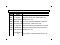
FUNCTION MENU
The keypad can provide access to a wide assortment of utility functions. The functions are displayed in a prompting "YES/NO" format.
From the Home Screen, tap Security, Other Options, Keypad Mode, then proceed as follows:
1 To enter the Function Menu, tap R.
• In all UL-listed or high-security installations, a valid User Code must first be entered followed by R.
2 To skip a function, answer NO (Q) or R.
3 To select and execute a function, answer YES (P) or U.
• Functions may be manually scrolled forward or backward using R and B, respectively.
• To return to normal keypad operation, tap the C button. The keypad will automatically return to its normal operating
mode if no activity is detected for longer than one minute.
DISPLAY
ZN FAULTS
DISPLAY
ZN BYPASSED
Display Zone Faults? Displays the zone number of zones that are not secured. If
Y/N
needed, tap the NEXT and PRIOR Buttons, as displayed on-screen, to scroll faulted zones
(required for GEM-P3200/9600/X255 panels. GEM-P816/1632 panels will auto-scroll).
Displays bypassed zones. If needed, tap NEXT (P)
and PRIOR (Q) to scroll bypassed zones (required for GEM-P3200/9600/X255 panels.
GEM-P816/1632 panels will auto-scroll).
Display Zones Bypassed?
Y/N
DISPLAY
ZN DIRECTORY Y/N
Display Zone Directory? Displays a listing of all zones in the Area. If needed, tap
NEXT (P) and PRIOR (Q) to scroll zone directory (required for GEM-P3200/9600/
X255 panels. GEM-P816/1632 panels will auto-scroll). (Note: This function available with
GEM-P1632 control panel firmware version 9a or later).
26
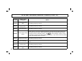
FUNCTION MENU
ACTIVATE
SIREN TEST
Activate Siren Test? Activates the alarm (while disarmed) for about 2 seconds and
Y/N
Display System Troubles? Displays 1- or 2-digit error code along with a description of
SYSTEM TBL
Y/N
DISPLAY
FIRE ALARM
DISPLAY
FIRE TRBL
ACTIVATE
CHIME
ACTIVATE
WATCH
performs a battery test. If the alarm does not sound, call for service.
• If the battery is low, a "LOW BATTERY E02-00 SERVICE" will appear in the display
indicating a low battery condition. Allow 24 hours for the battery to recharge. If the
trouble continues, call for service.
a problem detected in the system. (See SYSTEM TROUBLE ERROR CODES for a full
description of these codes). Use NEXT (P) and PRIOR (Q) to scroll system
troubles. (For GEM-P3200/9600/X255 panels only).
Display Fire Alarms? Displays alarms that have occurred on the Fire Zone(s). Tap the
Y/N
NEXT and PRIOR Buttons to scroll zones (required for GEM-P3200/9600/X255 panels.
GEM-P816/1632 panels will auto-scroll).
Display Fire Troubles? Displays trouble conditions that have been detected on the Fire
Y/N
Zone(s). Use NEXT (P) and PRIOR (Q) to scroll zones (required for GEMP3200/9600/X255 panels. GEM-P816/1632 panels will auto-scroll).
Activate Chime? The Chime Mode will sound a tone at the keypad when the
Y/N
programmed zone is faulted while disarmed. To deactivate the Chime Mode, re-enter the
Function Mode and when "DEACTIVATE CHIME" is displayed, tap YES (P). Note:
The Chime Mode is disabled while armed.
Activate Watch Mode? (Optional - Watch Mode programmed? YES NO) This
Y/N
optional feature simultaneously turns on all zones designated as Day Zones, which will
cause an indication at the keypad if a zone is opened while the system is disarmed. To
deactivate the Watch Mode, arm, then disarm. All Day Zones will revert to regular Burglary
Zones. Note: The Watch Mode is disabled while armed. (Note: This function available with
GEM-P9600 and GEM-P3200 control panels only).
27
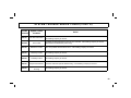
FUNCTION MENU
RESET
SYS TRBL
RESET
SENSOR MSG
Y/N
Y/N
Reset System Trouble? System troubles display and sound at the keypad. Correcting
the trouble will clear most indications, however the following error codes will require
manual reset: E13; E19; E20 and E22. (See SYSTEM TROUBLE ERROR CODES for a
description of error codes.)
Reset Sensor Watch Failure? (Sensor Watch programmed? YES NO).
Your system may have been programmed for Sensor Watch, a feature which
supervises the motion sensors in the system. If a Sensor Watch failure occurs, a
System Trouble E22-NN will result, where NN represents the zone number of the
sensor in question. To reset, tap C to clear the display, enter the Function Menu,
scroll to "RESET SENSOR MSG" and tap U. If you cannot correct the problem, call for
service. (Note: This function available with GEM-P9600 and GEM-P3200 control panels only).
START
EXIT TIME
Y/N
Start Exit Time? (Optional) (Start Exit Time programmed? YES NO)
In Commercial Burglary systems, exit delay may have been programmed to start after a
central-station "ringback" (verification) signal has been received. If the ringback tone
has not been received within about 30 seconds after arming, a communication problem
may exist. Use this function to start exit delay manually, then exit the premises
immediately. Be sure to have your alarm specialist check communications with the
central station as soon as possible. (Note: This function available with GEM-P9600 and GEMP3200 control panels only).
28
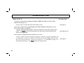
FUNCTION MENU
ACTIVATE
DIALER TEST
Y/N
TO ARM IN 1-4 HRS
PRESS 1-4
/N
Activate Telephone Test? (Telephone Test programmed? YES NO). Sends a
communicator test to the central station. A communication failure will be indicated
at the keypad by a system trouble "E03-FAIL TO COMM" display. Repeat the test
to attempt to correct a communication failure, as any successful communication
will clear this display.
Delay Arming 1-4 hours. (Not for UL-listed systems). Your system may be set to
arm automatically after a delay period of 1 to 4 hours.
To Delay Arm the system:
• With the function "TO ARM IN 1-4 HRS" displayed in the window, enter the
desired Delay Arming time in hours (1, 2, 3,or 4), followed by U.
TO DELAY AUTOARM
PRESS 1-4
/N
(display for GEM-P3200 / 9600 / X255)
At the end of this 1 - 4 hour Delay Arming period, the siren will sound a 2-second
warning and the keypad will begin a 15-minute arming countdown with the sounder
pulsing. The sounder may be silenced at this time by tapping C, but it will turn
back on with a steady warning tone 1 minute prior to arming, at which time the
building must be exited.
The same steps can be used to delay a scheduled Auto Arming, if your system has
been programmed as such.
29
FUNCTION MENU
ACTIVATE
PROGRAM
ACTIVATE
DOWNLOAD
RELAY
CONTROL
Y/N
Activate Program? Activates the Program Mode from Keypad No. 1. Note: This
feature is disabled while armed. (See PROGRAMMING USER CODES)
Y/N
Activate Download? For installer's use only. If accidentally enabled, tap C
to exit. Note: This feature is disabled while armed.
Y/N
Relay Control? (Relay Control programmed? YES NO).
Turns ON or OFF one or more programmed Relay Groups. Tap
U to turn the
displayed group on or off; tap NEXT (P) to proceed to the next group, or
PRIOR (Q) to scroll back to the previous group. Tap C when done. (Note:
This function available with GEM-P3200/9600/X255 control panels only).
• Relay Group 01: [ ____________________________________ ]
• Relay Group 02: [ ____________________________________ ]
• Relay Group 03: [ ____________________________________ ]
• Relay Group 04: [ ____________________________________ ]
• Relay Group 05: [ ____________________________________ ]
• Relay Group 06: [ ____________________________________ ]
• Relay Group 07: [ ____________________________________ ]
• Relay Group 08: [ ____________________________________ ]
30
C E N T R AL S T A T I O N M O N I T O R I N G
Your alarm specialist may have
programmed your system to be
monitored by a central station. The builtin digital communicator can transmit
emergency signals and status reports to
the central station 24 hours a day.
Opening and/or Closing Reporting.
Your system can notify the central
station every time it is disarmed or
armed. Any or all of up to 96
different users can each be
identified. If your system reports on
arming (Closing Report), the central
station will acknowledge arming.
This will signal at the keypad as a
“ringback” beep. Note: If the
ringback signal is not heard, call for
service.
Communicator Features
Abort Delay. Ask your installer which
of your zones have Abort Delay, a
delay that enables you to reset the
system before it communicates to
the central station. Your system
has a SIA CP-01 required Abort
Delay of 30 seconds. It may be removed or increased up to 45 seconds (at your option) by consulting
with your installer.
Regular Burglary (Non-24-Hour) Zone
reports are aborted by disarming
within the delay period. 24-Hour
Zones and zones programmed to
report restores must be restored
first, then the panel armed and
disarmed, all within the delay
period.
31
A D V AN C E D F E AT U R E S
Security Bypass/Unbypass
(Security Bypass programmed? YES NO).
In high-security applications, zones may be bypassed (or unbypassed) only if a valid code is entered first, as follows:
1. Enter a User Code valid for bypass, then tap B.
2. Tap B then the zone number (or vice versa) to deactivate that zone.
Similarly, a bypassed zone may be unbypassed using the same procedure.
(This feature available for GEM-P3200/9600/X255 panels only).
Start Exit Time After Ringback (for Commercial Burglary Systems only)
(Optional - Start Exit Time programmed? YES NO).
If your system reports to a central station, your panel may have been programmed to start exit delay after the central-station
ringback (verification) signal. Then, after arming, your system will communicate to the central station. After the central station
acknowledges receipt (ringback), exit delay will start. If ringback is not heard within about 30 seconds, a communication
problem may exist; call for service. Function 11 (Start Exit Time) may then be used to manually start the exit delay, however
reporting capability may be sacrificed. (If your system does not report or the ringback feature was not programmed, exit delay
will start as soon as your code is entered. Also note that if an exception window is programmed, and the closing is within that
window, no ringback is provided. Ask your alarm professional if this feature is enabled.) (This feature available for GEMP3200/9600/X255 panels only).
Exit-Delay Restart
(Exit-Delay Restart programmed? YES NO).
On arming, the programmed exit delay will start. After the exit/entry door has been opened and then closed, exit delay will restart if the door is opened again. The Exit-Delay Restart feature will occur one time only in any arming period. (This feature
available for GEM-P3200/9600/X255 panels only).
32
P R O G R AM M I N G ( O P T I O N A L )
User Program Mode
Your Installer has programmed into your system a special User Program Code which can be used to not only Arm and Disarm the
system, but also to enter the User Program Mode, where you can program other User Codes, Zone Descriptions and also set the
system Time and Date. The following explains how you will use this code to program or erase additional User Codes:
Enter the User Program Mode
ACTIVATE
PROGRAM
Y/N
1. Enter your User Code, then tap R to enter the Function Mode.
2. Answer NO until “ACTIVATE PROGRAM Y/N” is displayed, then tap YES. “ENTER USER
CODE” will display indicating that the system is ready for User Code programming.
ENTER USER CODE
123
- -
Programming / Reprogramming a User Code
ENTER USER CODE
- -
3. Tap
1. Enter the digits of the user number to be programmed, followed by RR. (Example:
For User 4, enter "04 RR"). (For the GEM-X255 panel, enter all three digits of the user number).
2. Enter the new User Code. Note: User Codes may be up to 6 digits in length.
U to save the new User Code.
Duplicate Codes are not allowed; therefore a duplicate
Code entered in the LCD Window will erase when U is tapped.
Repeat Steps 1 through 3 for each User Code to be programmed.
ENTER USER CODE
4567 - Note: The GEM-X255 panel will display
users in 3 digits, for example:
001
4567
-
-
Erasing a User Code
1. Enter the digits of the user number to be erased followed by RR.
2. Tap G0 to erase each digit of the User Code and then tap U.
• Example: Erase User 3’s 4-digit User Code: (For the GEM-X255 panel, enter all three digits of the User #).
• Tap 03RRG0G0G0G0 U.
33
P R O G R AM M I N G ( O P T I O N A L )
Reviewing a Programmed User Code
To review an existing User Code, enter the user number and the corresponding User Code will display. (For the GEM-X255
panel, always enter all three digits of the user number).
Exiting the User Program Mode
When you have completed programming or erasing User Codes, tap C to exit the User Program Mode.
Programming Example:
Program the User 3 Code to "3784".
1. Enter your User Code, followed by R.
2. Answer NO (tap Q ) repeatedly until "ACTIVATE PROGRAM Y/N" is displayed, then tap YES (P). The
display will read: "ENTER USER CODE"
3. Tap 03 for User No. 3, then tap R, R, followed by 3784. (For the GEM-X255 panel,
enter all three digits of the user number).
4. Tap U to save the code. Note: Duplicate Codes are not allowed; therefore a duplicate Code entered in the
LCD Window will erase when U is tapped. Tap C to exit the Program Mode.
Notes:
• If the system contains more than one keypad, only the keypad designated "No. 1" may be used for programming (if in
doubt which is No. 1, ask your installer).
• While in Program Mode, burglar and fire alarm functions are disabled.
• In selecting your codes, do not program repetitive numbers (1111), consecutive numbers (1234), your birth date, address, or other
obvious combinations. Choose a code of up to six digits (a minimum of four is recommended, and required in UL installations). If
the keypad detects no Program Mode activity for more than about 4 minutes, three short beeps will sound. Tap C to silence.
34
P R O G R AM M I N G ( O P T I O N A L )
Programming Zone Descriptions
The zone descriptions which appear on the keypad display may be programmed using the standard wired keypad in the User
Program Mode.
Enter the User Program Mode
ACTIVATE
PROGRAM
Y/N
01- FRONT DOOR
CELL PHONE-STYLE ENTRY
HOLD
G
1.
2.
Enter your User Code, then tap R to enter the Function Mode.
3.
"ENTER USER CODE" will display, tap NEXT (P) and the keypad will display
the Zone 1 Description.
Answer NO (tap Q) until "ACTIVATE PROGRAM Y/N" is displayed, then tap
YES (P).
Entering a new zone description (Cell Phone-Style Entry)
•
•
Use buttons R and B to move the cursor under the letter to be changed.
•
Use buttons R and B to move the cursor as needed. Tap U to save.
CHARACTERS
DISPLAYED
IN SEQUENCE
AND TAP
CHARACTERS
DISPLAYED
IN SEQUENCE
1
ABC1
1
abc1
2
DEF2
2
def2
3
GHI3
3
ghi3
4
JKL4
4
jkl4
5
MNO5
5
mno5
To advance to the next zone (or to any other zone):
• Move the cursor to the displayed zone number (i.e., "01") using R and B.
6
PQR6
6
pqr6
•
7
STU7
7
stu7
8
VWX8
8
vwx8
9
YZ90
9
yz90
0
(SPACE) • - .
( ) , / : ? #
0
(Reserved)
TAP
•
Tap 0 through 9 and G to select letters. The first tap will display the
first character, the next tap will display the next character. See the table at left and
page 36 for more information.
Change the zone number using keys 0 through 9. Enter two digits for the
zone number (after entering the first digit, the cursor will automatically advance to
the second digit). When the second zone number digit is entered, the cursor will
automatically advance to the right, allowing the description locations to be entered.
Always tap U to save each zone description.
35
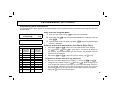
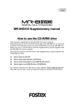
ENTER ZONE DESCRIPTIONS -- "CELL PHONE STYLE"
EXAMPLE: Repeatedly tap 3
to display "G H I 3" in sequence
CELL PHONE-STYLE ENTRY
36
HOLD
G
TAP
CHARACTERS
DISPLAYED
IN SEQUENCE
AND TAP
CHARACTERS
DISPLAYED
IN SEQUENCE
1
ABC1
1
abc1
2
DEF2
2
def2
3
GHI3
3
ghi3
4
JKL4
4
jkl4
5
MNO5
5
mno5
6
PQR6
6
pqr6
7
STU7
7
stu7
8
VWX8
8
vwx8
9
YZ90
9
yz90
0
(SPACE) • - .
( ) , / : ? #
0
(Reserved)
U
R
1
2
3
(RIGHT)
ABC1
DEF2
GHI3
B
4
5
6
(LEFT)
JKL4
MNO5
PQR6
(SAVE)
C
7
8
9
0
STU7
VWX8
YZ90
(SPACE)
• - . ( ) ,
/ : ? #
Use R and B buttons to move the cursor as needed. Tap U to save.
Hold G and tap the number to display lowercase letters in sequence.
P R O G R AM M I N G ( O P T I O N A L )
Programming the system Date and Time.
The User Program Mode may also be used to set the system Date and Time which display on the keypad.
ACTIVATE
PROGRAM
Enter the User Program Mode
Y/N
ENTER DATE
00/00/00
1.
2.
3.
Enter your User Code, then tap R to enter the Function Mode.
Answer NO (Q) until "ACTIVATE PROGRAM Y/N" is displayed, then
tap YES (P).
"ENTER USER CODE" will display, tap NEXT (P) until the keypad
displays the "Enter Date" screen.
Programming the Date
ENTER DATE
07/29/18
1.
At the Enter Date screen, simply punch in the correct date using the numeric
keypad buttons.
For example, for July 29, 2018, enter: 07 29 18
2.
Tap
U
to save the Date.
Programming the Time
ENTER TIME
(12:00A)
After entering in the Date, tap NEXT (P) for the Time Entry screen.
1. At
the Enter Time screen, simply punch in the correct time using the numeric
keypad buttons and if necessary, tap any numeric button to change the AM
display to PM (or vice versa).
ENTER TIME
For example, for 6:30 PM, enter: 06 30 (0if necessary)
(06:30P)
2.
Tap U to save the Time.
37
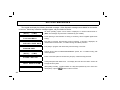
K E Y P AD M E S S AG E S
The keypad can display the following functional messages. Other diagnostic messages are available for the installer
or servicer. Should any unfamiliar messages appear, call your dealer for service.
SYSTEM READY
(DATE)
(TIME)
C
PLEASE WAIT
FOR RINGBACK
Panel reporting to central station on arming. If necessary, wait for ringback signal before
exiting.
EXIT TIME XXX
PLEASE LEAVE NOW
Exit delay in progress. XXX denotes exit time remaining, in seconds. If displayed, "S"
indicates Service Code active; "I" indicates arming with Instant protection.
ENTRY TIME XXX
DISARM NOW
Entry delay in progress. XXX shows entry time remaining, in seconds.
ARMED STAY I
(DATE)
(TIME)
System armed. With the GEM-P3200/9600/X255 panels, the "I" indicates arming with
Instant protection.
ZONES FAULTED
Zones not secured (doors or windows may be open). Faulted zone(s) will scroll.
ZONES NOT NORMAL
CAN'T ARM SYSTEM
*DAY ZONE TRBL*
38
All zones operating; system can be armed. If displayed, "C" denotes Chime Mode on.
(Note: This message may have been customized by your installer.)
Arming attempted with faulted zone. The display will scroll the zone faults. Secure the
zone(s) and arm system.
(With pulsing sounder). Trouble condition on a Day Zone (followed by one or more zone
descriptions). Tap the C button to silence sounder.
K E Y P AD M E S S AG E S
****ALARM****
Alarm condition, followed by zone description(s). “ALARM” and zones will display after
system is disarmed. Note zones, then tap C to clear keypad.
***FIRE TRBL***
(With pulsing sounder.) Trouble condition on a Fire Zone.
sounder. Correct trouble or call for service.
***FIRE ALARM***
(With pulsing sounder.) Alarm condition on a Fire Zone. Tap C to silence sounder.
Evacuate premises or correct cause of alarm.
CODE DENIED
INCORRECT AREA
INVALID ENTRY
TRY AGAIN
CAN’T ARM
SYSTEM/
AREA # IN TROUBLE
Tap C to silence
(For partitioned systems only); code not valid for area.
Wrong code entered.
(In Manager's Mode.) Arming prevented due to unsecured zone. “#” represents number
of area with unsecured zone. Tap the area number, then the G button, then
view zones in that area. Correct problem, then arm as normal.
P1632/1664/3200/9600/X255 panels only).
U to
(For GEM-
39
K E Y P AD M E S S AG E S
40
ATTEMPTING TO
CANCEL
The system is in the process of reporting a cancel signal to central station which will
cancel the alarm which it has just reported.
ALARM CANCELED
The alarm signal has been cancelled during the Abort Delay (before an alarm signal
report was sent to the central station). If cancelled after the alarm signal report was
sent, this message appears when the system receives an acknowledgment from the
central station of the cancellation of the alarm signal.
*SYSTEM TROUBLE*
Indicates problem(s) detected on system. (See examples below and SYSTEM
TROUBLE ERROR CODES for a complete list of system troubles and corrective
actions.)
AC POWER FAIL
E01-00 SERVICE
Check power transformer. Check for blown fuse or circuit breaker; general power
outage.
LOW BATTERY
E02-00 SERVICE
Battery weak. If not recharged within 24 hours, replace battery.
COMM FAIL
E03-00 SERVICE
Communication failure to central station.
U S I N G T H E O N S C R E E N K E Y B O AR D
Standard Keyboard
The "Standard" onscreen keyboard allows you to type text, numbers and other characters. With
some applications, the onscreen keyboard opens automatically; most other applications (such
as in the Caption popup shown at right) require you to tap a text field to open the keyboard.
Tap to save when
finished typing
Backspace
(Moves cursor one
column to the left,
deleting the character
in that position)
Shift
Tap twice (or press
and hold) for ALL
CAPS (light turns on)
Symbols
Tap to switch to the
numbers and symbols
keyboard (see next
page for more options)
Period
Press and hold to open a small window
with a set of common symbols
Enter
("Return key") Tap to
end a paragraph
41
U S I N G T H E O N S C R E E N K E Y B O AR D ( C O N T ' D )
Numbers and Symbols
On the "Standard" keyboard shown on the previous page, tap the "?123" key and switch to
the "Numbers and Symbols" keyboard shown below.
Tap to save when
finished typing
Backspace
(Moves cursor one
column to the left,
deleting the character
in that position)
ALT
Tap for additional symbols shown on next
page
(light turns on)
ABC
Tap to switch back to
the "Standard"
keyboard (shown on
previous page)
42
Period
Press and hold to open a small window
with a set of common symbols
Enter
("Return key") Tap to
end a paragraph
U S I N G T H E O N S C R E E N K E Y B O AR D ( C O N T ' D )
Additional Symbols
On the "Numbers and Symbols" keyboard shown on the previous page, tap the unlit "ALT"
key and switch to the "Additional Symbols" keyboard shown below (ALT key is lit).
Tap to save when
finished typing
ALT
Tap to return to the
"Numbers and Symbols" keyboard shown
on previous page
(light turns off)
ABC
Tap to switch back to
the "Standard"
ALL CAPS keyboard
Backspace
(Moves cursor one
column to the left,
deleting the character
in that position)
Enter
("Return key") Tap to
end a paragraph.
43
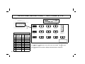
USER SETTINGS MENU
Tablet
Date and Time
Display
Screensaver Options
Sound
Touch Screen Calibration
Video
Camera List
Discover All Cameras
Home
Time Enable
Weather Options
Z-wave
IBR-ITAB Napco
Security Application
"User Settings"
Button
Remote Login
Wi-Fi Option
Voice
App Version
Reconnect
44
SETTINGS MENU ICONS
"TOP OF SCREEN" ICONS
When in the Settings menu, several active (touchable) icons appear at the top of IBR-ITAB screen:
3G
Go Back to Previous Screen:
Tap to return to the previous menu
level; if currently in the Settings
menu, returns to the Home
Screen.
Specialized Menu: Opens specialized menu buttons that appear
at the bottom of the screen. Buttons are unique for each applications (specialized menu buttons
are not available within all applications).
USB in Use: Indicates the USB
Socket located on the side of the
IBR-ITAB is in use (thumb drive,
portable hard drive, memory stick,
etc.). Note: This USB Socket is
for data transfer only (NOT for
charging).
Android: Appears when the Android operating system is in use.
Signal Strength Indicator: Displays the wireless signal power
between the IBR-ITAB and the
IBR-WIFI-MOD control panel interface module. Note the indicator
displays 3 bars; the more bars that
are lit, the stronger the wireless
signal.
Battery Charging: The IBR-ITAB
is correctly connected to its charging station and its integral battery
is charging.
Battery Charged: The IBR-ITAB
is removed from its charging station and is operating on integral
battery power only; battery is fully
charged.
3:48 PM
Battery Almost Drained: Battery
is almost depleted, reconnect to
charging station as soon as possible.
Device Options: Tap to open a
popup with the following selections: Screen lock powers down
the IBR-ITAB display while the
IBR-ITAB remains in operation
(press the Back / Power button to
resume); Reboot restarts the IBRITAB; Power off turns off the IBRITAB.
Battery 1/2 Full: Battery is approximately half drained.
45
U S E R S E T T I N G S > T AB L E T
Date and Time:
Automatic: When checked to enable, retrieves IBRITAB date/time data automatically from network resources. When enabled, the next three selections are
ghosted ("grayed out" and not selectable).
Set date: Tap to open a dialog that allows the month,
day and year to be manually set in the IBR-ITAB.
Note: The "Automatic" menu selection (above) must
be unchecked to enable this menu item.
Select time zone: Tap to select a time zone to be
used in the IBR-ITAB. Note: The "Automatic" menu
selection (above) must be unchecked to enable this
menu item.
Set time: Tap to open a dialog that allows the current
time to be manually set in the IBR-ITAB. Note: The
"Automatic" menu selection (above) must be unchecked to enable this menu item.
Use 24-hour format: Check to display 24-hour military time, as measured in hours numbered to twentyfour from one midnight to the next. For example, 3:23
pm would be displayed as "15:23".
Select date format: Tap to open a dialog that allows
the selection of the following date formats:
46
•
•
•
•
Normal (12/31/2011) (Month/Day/Year)
12/31/2011 (Month/Day/Year)
31/12/2011 (Day/Month/Year)
2011/12/31 (Year/Month/Day)
Display - Allows changes to the IBR-ITAB display screen.
Brightness: Tap to open a sliding status bar control.
Increase or decrease the screen brightness by sliding
your finger left or right across the status bar.
Auto-rotate screen: Not used.
Animation: Tap to open a pull-down menu where
you can select "No animations" to disable all optional
animation effects, "Some animations" to enable animated transitions for some effects, or "All animations" for all supported effects including screen to
screen navigation attributes. Note: The "No animations" setting does not control animation in all applications.
Screen timeout: Specifies how much user idle time
(IBR-ITAB is operational but not being used) must
elapse before the screen turns off. The default setting
is "never". Note: When this feature is enabled and
the screen dims, the IBR-ITAB also enters "sleep
U S E R S E T T I N G S > T AB L E T ( C O N T ' D )
mode", an inactive state to save power. To reawaken, touch any non-screen button. Screen timeout selections include 15 seconds, 30 seconds, 1 minute, 2 minutes, 10 minutes, 30 minutes and never.
TV Mode: (Reserved for future use)
TV Resolution: (Reserved for future use)
TV HDCP: (Reserved for future use)
Screensaver Options - IBR-ITAB screen options that activate after a selected user idle time duration (IBRITAB is operational but not being used).
Screen dim timeout: Reduces the IBR-ITAB screen
brightness to zero (dark) after the selected duration ends
and the idle time duration begins (15 or 30 seconds, 1,
2, 5, or 20 minutes). To disable the screen dim feature,
select "Never Timeout". Note: When this feature is enabled and the screen dims, the IBR-ITAB also enters
"sleep mode", an inactive state to save power. To reawaken, touch the screen. This feature will automatically wake up when an entry delay or alarm is detected.
Screen Darkness: Allows the selection of darkness
percentage after the screen dim timeout duration
starts. Often used in bedroom locations. Selections
range from 0% (no dim/bright) to 100% (fully dim to
black) in 10% increments.
Sound - Controls sound intensity and feedback settings.
Volume: Tap to open a dialog containing sliding
status bar controls to set the Media volume, Alarm
volume and Notification volume intensity.
Audible selection: Check to play a sound when certain icons, keys, buttons and other onscreen items are
touched.
Screen lock sounds: Check to play sounds when
the IBR-ITAB display screen is locked or unlocked.
Haptic feedback: Check to briefly vibrate the IBRITAB when certain icons, keys, buttons and other onscreen items are touched (unavailable with some models).
Touch Screen Calibration - Tap to start the IBR-ITAB's
internal touch screen calibration process that directly
defines the boundaries of the sensor areas within the
IBR-ITAB's touch screen. When the calibration process starts, simply tap the light blue cross ("+") that ap47
U S E R S E T T I N G S > T AB L E T ( C O N T ' D )
pears on the touch screen. Each time the cross is
tapped, it re-appears at a different location on the
screen; tap the cross each time it re-appears on the
screen until the calibration process ends and the System Settings menu selections re-appear.
Note: The Touch Screen Calibration screen can be
entered at any time by pressing and holding the
"Home" button at the top edge of the IBR-ITAB (the far
right button of the 4 buttons along the top of the housing).
48
USER SETTINGS > VIDEO
Use the Video menu to make changes to the video data settings received by the IBR-ITAB.
Camera List - Displays a list of all active video cameras in your system.
Discover All Cameras - Initiates the network scanning process that discovers all cameras attached to the iBridge network. Upon discovery, the video for the discovered cameras will be available for display from the IBR-ITAB Home
Screen (Video button).
49
USER SETTINGS > HOME
Time Enable - Check to enable the IBR-ITAB to display
the time on the Home Screen. Also automatically
corrects for Daylight Saving Time.
Weather Options - Local weather reports can be displayed on the Home Screen.
Refresh Frequency: Tap to set how often to
automatically update the weather report feed. Selections include 5, 10, 15, 20, 30, 40, 50, 70, 80,
90 and 100 minutes. More frequent updates increase data use and slightly decrease battery life
between charges.
Weather Feed: Check to display a weather report feed on the Home Screen. Uncheck to remove the weather feed from the Home Screen.
Note: To customize the weather report feed to a
particular Zip Code, see the following menu entries below.
50
Zip code entry: Check to associate the weather
report feed to the area of the United States specified by the Zip Code entered in the field below.
Uncheck to disassociate the weather feed from
this Zip Code.
Zip Code: Tap to set the Zip Code to which the
Weather Feed is associated.
Update Z-Remote Clock - Synchronizes the IBRZREMOTE module internal clock with the same
time as the IBR-ITAB.
U S E R S E T T I N G S > Z - W AV E
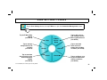
Tap the User Settings button, then tap Z-Wave* to open the Automation Management screen.
Tap for Z-Wave Help
Menus
(see OI378)
Help
Tap to manage
multiple devices at
one time
(see OI378)
Tap to associate
alarm events to your
home automation
system
(see OI378)
*If not enabled, see contact your security dealer
Groups
Events
Z-Wave
Device
Setup
Cameras
Scenes
Tap to add, remove,
and configure your ZWave system devices
(see OI378)
Tap to associate
alarm events to
trigger the recording
of videos (see OI378)
Tap to configure up to
32 pre-set home automation conditions
(see OI378)
51
U S E R S E T T I N G S > REMOTE LOGIN, WI-FI OPTION, VOICE, APP VERSION
Remote Login - Allows secure access to your system
through a network outside of your home network.
Note: This setting only appears for the model
IBR-ITAB, and will not appear for the model IBRITAB-HW.
You do not need to be at home to access your
alarm system, your Z-Wave devices or your video
cameras. You can access all parts of your system
using any web-enabled device, including your
web-enabled IBR-ITAB itself.
To allow secure access to your system through a
network outside of your home network (for example at a café or other web-enabled location), the
User Settings > Login screen allows a Username, Password and Display Name to be required
before a connection outside of your home network
is permitted.
Thus if the IBR-ITAB is lost or misplaced, access to
your home system via an external network will be
restricted.
To automatically save the Username, Password
and Display Name within the IBR-ITAB to allow
automatic login to your home network via any outside network, simply check the Save Password
checkbox, then tap Save. To discard all data and
52
exit without saving a Username, Password or Display Name, tap Clear.
Wi-Fi Option - Check to enable the wireless connection between the IBR-ITAB and the IBR-WIFI-MOD. Uncheck to manually disable the wireless connection.
Note: This menu selection appears within other Android Settings menu selections.
Voice - Check to enable voice annunciation of security system status. For example, if this feature is enabled
(checked), when arming the security system in
STAY mode, the IBR-ITAB will annunciate "Arming
in STAY mode" when the STAY button is tapped.
App Version - Displays the version of the Napco Security
Application currently installed within the IBR-ITAB.
Reconnect - Tap to break the wireless connection between the IBR-ITAB and ISEE-WAP and attempt
to reestablish the wireless connection.
I B R - I T AB " V I D E O " B U T T O N
If your system has video cameras, tap the Video button to
view real-time video feed for up
to four (4) cameras.
Video
You can tap one of the images
to enlarge, or tap one of the
four buttons located at the right
side of the screen:
Home - Tap to go to the IBR-ITAB Home Screen.
Emergency Buttons - Tap to signal a Fire, Police or Auxiliary (for example, medical)
emergency. Only available if programmed, then
always active.
Camera Discovery - Tap to initiate the network
scanning process to find all cameras attached to
the iBridge network.
Refresh - Tap to refresh the images (i.e. manually requesting the latest video feed from the network).
Video Tools - Jumps directly to the User Settings > Video menu, to allow changes to the
video data settings received by the IBR-ITAB.
IBR-ITAB "Video screen"
53
I B R - I T AB " AP P L I C AT I O N S " B U T T O N
Tap the Applications button to access the software
programs installed on your
IBR-ITAB.
Some programs are pre-installed at
the factory, including:
Browser: Tap to open a
web browser application,
to access the Internet.
Calculator: Tap to perform basic arithmetic operations, including addition, subtraction, multiplication and division.
Gallery: Tap to open a GUI that allows you to view image
files stored on your IBR-ITAB. Tap the "Set as" icon to crop
your image file, tap Share (requires appropriate file-sharing
software to be installed in your IBR-ITAB), or tap Delete the
remove the file from your IBR-ITAB.
Napco: Tap to log into your iSee Video site, allowing remote high-resolution streaming video Internet monitoring.
See your alarm dealer or www.napcosecurity.com/video.
html for more information.
Settings: Tap to enter the dealer User Settings menu
(User Settings > Tablet > Android Settings menu), as detailed earlier in this manual.
IBR-ITAB "Applications screen"
54
Touch Calibrator: Opens the Touch Screen Calibration
utility. Tap to start the IBR-ITAB's internal touch screen calibration process that directly defines the boundaries of the
sensor areas within the IBR-ITAB's touch screen. When the
calibration process starts, simply tap the light blue cross
("+") that appears on the touch screen. Each time the cross
I B R - I T AB " AP P L I C AT I O N S " B U T T O N ( C O N T ' D )
is tapped, it re-appears at a different location on the screen;
tap the cross each time it re-appears on the screen until the
calibration process ends and the System Settings menu selections re-appear.
Voice Recorder: Tap to open the digital audio recorder; tap
the Record button to begin recording, then tap Stop to
name and save the digital audio file. Once saved, the file
can be tapped to open a selection of operations, including:
Play: Tap to play the audio recording using the IBRITAB's speaker.
Send: Tap to email the file if the appropriate email application software is installed in your IBR-ITAB.
Ringtone: If a telephone application is installed, tap
Phone to assign the audio file to play as the audible
sound made by an incoming telephone call, or tap Notification to assign the audio file to play for incoming
messages or other IBR-ITAB alerts.
Edit Title: Tap to rename the audio file name.
Delete: Tap to remove the file from your IBR-ITAB.
55
G L O S S AR Y
Following are brief descriptions of terms and features used herein that may be unfamiliar to you. Some of the features are
programmable options that may or may not apply to your particular system.
Abort Delay - A delay period that
allows the control panel to be reset,
thus aborting a report to a central
station.
Access Code - A code (up to 6
digits) used to remotely unlock a
door.
Ambush Code - A code entered
when forced to disarm. Sends a
silent alarm to the central station with
no indication at the keypad. There
are two types: (1) A 2-digit code
(prefix) entered just prior to your normal User Code and (2) A separate and
unique User Code used in place of
your normal User Code.
Area - Some systems may be
divided, or partitioned, into smaller
independent subsystems, which are
referred to as Areas. Each Area may
be controlled by its own keypad or by
56
a keypad of a different Area through
Managers Mode.
Arming/Disarming - Turning the
system on/off by entering your code
at the keypad, then tapping U.
Battery - Backup power source in
the control-panel enclosure to
provide protection in the event of a
power failure.
BYPASS Button - Enables you to
manually remove one or more
protective zones from the system.
Central Station - Monitors
incoming reports and emergency
messages from a digital
communicator and notifies the proper
authorities.
Chime - A keypad beep while
disarmed alerting that the
programmed zone has been opened.
Closing Window - (Optional.) A
time interval within which closing
(arming) is permitted without
reporting to the central station.
Communicator - Reports
intrusions, emergencies, openings,
closings, etc. directly to the central
station over telephone lines.
Control Panel - The brain of the
system, it controls all system
functions.
Directory - A listing of the
programmed zone descriptions
stored in memory.
Easy Arming - Quick arming by
tapping U (optional).
G L O S S AR Y ( C O N T ' D )
Exit/Entry Delays - Separate
delays that let you exit and enter your
premises without setting off an alarm
when the system is armed.
Instant Protection - Arming
without entry delay using the Q
button while remaining on the
premises.
Keypad - Puts control-panel
functions at your fingertips. It can be
mounted anywhere in your premises.
Manager's Mode - In a partitioned
system, a low-security operating
mode that allows arming by area.
Panic Buttons - Used to signal a
Fire, Police or Auxiliary emergency
(for example, a medical emergency).
Partitioned System - A system
that has been subdivided into two or
more (up to eight) independent
subsystems (areas).
Pre-Alarm Warning - A keypad
sounder alert of an impending alarm.
This option is programmable by zone
for the same duration as that
programmed for Abort Delay (see
Abort Delay).
Report - A transmission to a central
station notifying of a change in the
status of the system (alarm, trouble,
low battery, etc.).
at each keypad to alert that (a) entry
delay has started; (b) an attempt was
made to arm with a zone in trouble;
(c) a Day-Zone condition exists (see
Zones: Day Zone); (d) 10 seconds
exit time remaining; (e) invalid code
entered; or (f) central station
acknowledged arming (see
Ringback).
RF Low Battery - (Wireless systems only) Weak transmitter battery.
System Trouble - A problem (low
battery, power failure, etc.) detected
in the system.
RF Check In - (Wireless systems
only) Periodic test report from
transmitter (if a report is not received
on time, a supervisory-failure system
trouble will result).
Trouble - A zone fault; an open
door, window, or other problem that
may prevent arming.
Ringback - A beep after arming
verifying the central-station's receipt
of a closing report.
User Code - Your personalized
code for arming and disarming the
system. It may contain up to six digits.
Service Code - A code intended for
temporary use.
Sounder - A local warning device
57
G L O S S AR Y ( C O N T ' D )
Zones - Independent circuits that
protect specific areas of the
premises:
Auto-Bypass Zone: A zone
that will be automatically
bypassed from the protection
system if it is in trouble
(faulty) when the system is
armed.
Burglary Zone:
intrusion.
Detects
Day Zone: A zone that will
cause a visual and audible
indication at the keypad if it
is in trouble while disarmed.
Exit/Entry Follower Zone:
Provides exit and entry delay
for interior devices. Entry
58
delay only occurs if re-entry
takes place through the
normal exit/entry door first.
Fire Zone: Detects fire alarms
or trouble conditions.
Interior Zones: Circuits within
t h e p r e m i s e s , u s ua l l y
including space-protection
devices, interior doors, etc.;
but not exterior doors or
windows. These can all be
bypassed simultaneously
using the P button.
Priority Zone: A zone that
prevents arming if in trouble.
Priority Zone with Bypass: A
Priority Zone that can be
bypassed using the C
button.
Selective-Bypassed Zone: A
zone that can be individually
bypassed using the B
button.
24-Hour Zone: A zone that is
armed and ready at all times
to respond to an emergency
situation.
SYSTEM TROUBLE ERROR CODES
Your control panel is capable of detecting a variety of troubles that may affect system performance. In the unlikely event that a
problem should occur, the SYS TBL (system trouble) icon will display on the left side of keypad window along with one or more of the
following error codes. If the problem is related to a specific zone or device, the corresponding number will also be indicated. Below is
a list of the most common troubles along with the necessary corrective action, if any. If a message appears that is not listed below,
call your security professional for service. When a system trouble occurs, the keypad can be silenced and the display can be cleared
by tapping C. The system can then be armed and disarmed as usual.
Note: If you cannot clear a system trouble yourself, call installing company for service as soon as possible.
Trouble
Indication
System Trouble
Condition
Action
E01-00
AC Power Failure
This trouble will occur if AC power is not present. Make sure system transformer is plugged into
AC receptacle and check the circuit breaker, otherwise call installing company for service.
Low Battery
If there has been a recent power failure, the battery may be partially depleted and must be
recharged by the control panel. The control panel performs an automatic daily test of the
battery, at which time the trouble will clear if the battery has been recharged.
If the trouble does not clear in 24 hours, call installing company for service.
E02-00
E03-00
Communication
Failure
The system was not able to report to central station. If this is due to a temporary interruption in
the telephone service, the trouble can be cleared when the service is restored by performing a
Communication Test:
1 While disarmed, enter your User Code followed by R.
2 Answer NO (Q) until “ACTIVATE DIALER TEST” appears in the window.
3 Tap YES (P) to send a test signal to the central station.
If the trouble continues, call installing company for service.
59
SYSTEM TROUBLE ERROR CODES (CONT'D)
Trouble
Indication
System Trouble
Condition
E04-NN
Wireless Transmitter
Supervisory Failure
E05-NN
Wireless Transmitter
Low Battery
Action
A problem has been detected with a wireless transmitter. Call installing company for service
The battery in a wireless transmitter is low and should be replaced. This transmitter is on the
zone corresponding to the number NN. The replacement battery for the GEM-TRANS2 door/
window transmitter, GEM-PIR motion detector and GEM-GB glass break detector is the Duracell
DL123A 3 volt lithium. (2 required for the GEM-PIR and GEM-GB.) The replacement battery for
the GEM-SMK is the Duracell MN1604 9 Volt Alkaline (2 required). The GEM-DT Dual
Technology Sensor requires 4 C cell alkaline batteries.
Warning: Replace batteries only with the same type as specified above. Use of another battery
may present a risk of fire or explosion. Do not recharge or disassemble battery, or dispose of in
fire.
60
E06-NN
Receiver Response
Failure
Call installing company for service.
E07-00
Download Failure
Call installing company for service.
E08-00
Telephone Line Cut
E09-00
System Cold Start
The telephone line has failed. If telephone service has been temporarily interrupted, the trouble
will clear automatically when it is restored. Otherwise, call installing company for service.
--
SYSTEM TROUBLE ERROR CODES (CONT'D)
Trouble
Indication
System Trouble
Condition
E10-NN
Keypad Response Failure
E11-NN
Keypad Tamper
E12-NN
Expansion Zone Module
Response Failure
E13-NN
Expansion Module Tamper
E14-NN
Relay Board Response FailNN= Relay Board Number. Call installing company for service.
ure
Action
Call installing company for service.
A keypad has been removed from the wall. Call installing company for service if
problem cannot be repaired.
Call installing company for service.
The cover has been removed from a zone expansion module. A problem has been
detected with an Expansion Module. Call installing company for service.
E15-NN
RF Transmitter Tamper
Wireless Transmitter Tamper Cover removed. NN=Transmitter Number. Call installing
company for service.
E16-NN
Wireless Receiver Jam
A problem has been detected with the wireless receiver. Call installing company for
service.
E17-NN
Receiver Tamper Condition
Call installing company for service.
The batteries (2) in the wireless KeyFob transmitter indicated are low and should be
replaced. The replacement battery is the #386 watch battery.
E18-NN
KeyFob Transmitter Low
Battery
Warning: Replace batteries only with the same type as specified above. Use of another
battery may present a risk of fire or explosion. Do not recharge or disassemble battery, or
dispose of in fire.
61
SYSTEM TROUBLE ERROR CODES (CONT'D)
Trouble
Indication
E19-00
Action
User Program Memory
Call installing company for service.
Error
E20-00
Dealer Program
Memory Error
Call installing company for service.
E21-00
System Shutdown
Call installing company for service.
E22-NN
62
System Trouble
Condition
A Motion Sensor on the zone indicated has failed the programmed Sensor Watch activity test.
Insure that the sensor is able to detect activity in the area; clear any obstacles which may be
Sensor Watch Activity blocking the sensor from detecting activity. Tap C to clear the display, and then use the
Failure
Function Menu to Reset Sensor Watch Failure (see page 28). If you cannot correct the problem
yourself, call installing company for service.
E23-00
Burglary Bus Failure
Call installing company for service.
E24-00
Service Message
E27-00
Printer Failure
Call installing company for service.
E39-00
Receiver Capacity
Error
Call installing company for service.
The system is in need of a preventive maintenance service call. Call installing company for
service.
SYSTEM TROUBLE ERROR CODES (CONT'D)
Trouble
Indication
System Trouble
Condition
E40-00
RF Self Test Failure
E41-NN
Fire Trouble
E51-00
Bell/Siren Trouble
There is a problem with the Bell or Siren. Call installing company for service.
E58-00
Telemetry Trouble
Call installing company for service.
E59-00
Telemetry Failure
Call installing company for service.
Action
A wireless motion sensor on the zone indicated has failed its automatic self test routine.
Call installing company for service.
A problem has been detected on the Fire zone indicated. Call installing company for service.
(GEM-P1632 and GEM-P816 panels only).
E66-00
Dirty Smoke Detector "Clean Me" indication (Smoke Detector dirty). Call installing company for service.
E99-00
Keypad Panic Shorted
Call installing company for service.
too Long
63
TROUBLESHOOTING
What do I do if...
For more info...
I try to arm my system but the keypad just displays “ZONES FAULTED” and “CAN’T ARM
SYSTEM” and beeps at me.
A zone is open. Find and secure the open window or door.
See Page 14
I try to arm my system but the keypad displays “SYSTEM TROUBLE” and beeps at me. The
Error Codes numbers are displayed.
A System Trouble has been detected. Note the scrolling error codes, which represent the
trouble. Tap C and you will now be able arm to the system, but the trouble must be
fixed as soon as possible.
See Page 20 & 28
The Fire Alarm is sounding and I don’t know how to turn it off.
If a fire is in progress, evacuate the premises immediately! If necessary, call the Fire Department from
an outside phone. If there is no evidence of a fire, enter your code and tap
U to silence the alarm.
Note the Zone Number displayed. Check the smoke detector(s). If a smoke detector tripped, its red
alarm indicator light will be on. Tap C to silence the keypad sounder.
64
See Page 22
NOTES
65
NOTES
66
C O P Y R I G H T & T R AD E M AR K S
R
Napco Security Technologies, Inc.
333 Bayview Avenue
Amityville, New York 11701
For Sales and Repairs, (800) 645-9445
For Technical Service, (800) 645-9440 or visit us at http://tech.napcosecurity.com/
(Note: Technical Service is for security professionals only)
Publicly traded on NASDAQ
Symbol: NSSC
www.napcosecurity.com
Certain features, services and applications are network dependent and may not be available in all areas; additional
terms, conditions and/or charges may apply. Contact your Internet service provider for details. All features, functionality, and other product specifications, as well as the information contained in this guide, are based upon the latest available information and believed to be accurate at the time of printing. Napco reserves the right to change or modify any
information or specifications without notice or obligation. Note: The diagrams and images in this guide are provided for
illustrative purposes only.
Important: Microsoft® and Windows® are trademarks the Microsoft Corporation. All other trademarks, service marks,
and product or service names described in this manual are for identification purposes only and may be trademarks or
registered trademarks of their respective owners. The absence of a name or logo in this document does not constitute
a waiver of any and all intellectual property rights that Napco Security Technologies, Inc. has established in any of its
product, feature, or service names or logos.
Caution: Napco does not take responsibility for changes/modifications to the transceiver.
© NAPCO 2013 All rights reserved.
67
N AP C O L I M I T E D W AR R AN T Y
NAPCO SECURITY SYSTEMS, INC. (NAPCO) warrants its products to be free from manufacturing
defects in materials and workmanship for thirty-six months following the date of manufacture. NAPCO will,
within said period, at its option, repair or replace any product failing to operate correctly without charge to
the original purchaser or user.
This warranty shall not apply to any equipment, or any part thereof, which has been repaired by others,
improperly installed, improperly used, abused, altered, damaged, subjected to acts of God, or on which
any serial numbers have been altered, defaced or removed. Seller will not be responsible for any
dismantling or reinstallation charges.
THERE ARE NO WARRANTIES, EXPRESS OR IMPLIED, WHICH EXTEND BEYOND THE
DESCRIPTION ON THE FACE HEREOF. THERE IS NO EXPRESS OR IMPLIED WARRANTY OF
MERCHANTABILITY OR A WARRANTY OF FITNESS FOR A PARTICULAR PURPOSE.
ADDITIONALLY, THIS WARRANTY IS IN LIEU OF ALL OTHER OBLIGATIONS OR LIABILITIES ON
THE PART OF NAPCO.
Any action for breach of warranty, including but not limited to any implied warranty of merchantability, must
be brought within the six months following the end of the warranty period.
IN NO CASE SHALL NAPCO BE LIABLE TO ANYONE FOR ANY CONSEQUENTIAL OR INCIDENTAL
DAMAGES FOR BREACH OF THIS OR ANY OTHER WARRANTY, EXPRESS OR IMPLIED, EVEN IF
THE LOSS OR DAMAGE IS CAUSED BY THE SELLER'S OWN NEGLIGENCE OR FAULT.
In case of defect, contact the security professional who installed and maintains your security system. In
order to exercise the warranty, the product must be returned by the security professional, shipping costs
prepaid and insured to NAPCO. After repair or replacement, NAPCO assumes the cost of returning
products under warranty. NAPCO shall have no obligation under this warranty, or otherwise, if the product
has been repaired by others, improperly installed, improperly used, abused, altered, damaged, subjected
to accident, nuisance, flood, fire or acts of God, or on which any serial numbers have been altered,
defaced or removed. NAPCO will not be responsible for any dismantling, reassembly or reinstallation
charges.
This warranty contains the entire warranty. It is the sole warranty and any prior agreements or
THE FOLLOWING STATEMENT IS REQUIRED BY THE FCC.
This equipment generates and uses radio-frequency energy and, if not installed and used properly, that
is, in strict accordance with the manufacturer's instructions, may cause interference to radio and
television reception. It has been type tested and found to comply with the limits for a Class-B computing
device in accordance with the specifications in Subpart J of Part 15 of FCC Rules, which are designed
to provide reasonable protection against such interference in a residential installation.
However, there is no guarantee that interference will not occur in a particular installation. If this
equipment does cause interference to radio or television reception, which can be determined by turning
Napco Security Technologies, 333 Bayview Avenue, Amityville, NY 11701
68
representations, whether oral or written, are either merged herein or are expressly canceled. NAPCO
neither assumes, nor authorizes any other person purporting to act on its behalf to modify, to change, or to
assume for it, any other warranty or liability concerning its products.
In no event shall NAPCO be liable for an amount in excess of NAPCO's original selling price of the
product, for any loss or damage, whether direct, indirect, incidental, consequential, or otherwise arising out
of any failure of the product. Seller's warranty, as hereinabove set forth, shall not be enlarged, diminished
or affected by and no obligation or liability shall arise or grow out of Seller's rendering of technical advice or
service in connection with Buyer's order of the goods furnished hereunder.
NAPCO RECOMMENDS THAT THE ENTIRE SYSTEM BE COMPLETELY TESTED WEEKLY.
Warning: Despite frequent testing, and due to, but not limited to, any or all of the following; criminal
tampering, electrical or communications disruption, it is possible for the system to fail to perform as
expected. NAPCO does not represent that the product/system may not be compromised or circumvented;
or that the product or system will prevent any personal injury or property loss by burglary, robbery, fire or
otherwise; nor that the product or system will in all cases provide adequate warning or protection. A
properly installed and maintained alarm may only reduce risk of burglary, robbery, fire or otherwise but it is
not insurance or a guarantee that these events will not occur. CONSEQUENTLY, SELLER SHALL HAVE
NO LIABILITY FOR ANY PERSONAL INJURY, PROPERTY DAMAGE, OR OTHER LOSS BASED ON
A CLAIM THE PRODUCT FAILED TO GIVE WARNING. Therefore, the installer should in turn advise the
consumer to take any and all precautions for his or her safety including, but not limited to, fleeing the
premises and calling police or fire department, in order to mitigate the possibilities of harm and/or damage.
NAPCO is not an insurer of either the property or safety of the user's family or employees, and limits its
liability for any loss or damage including incidental or consequential damages to NAPCO's original selling
price of the product regardless of the cause of such loss or damage.
Some states do not allow limitations on how long an implied warranty lasts or do not allow the exclusion or
limitation of incidental or consequential damages, or differentiate in their treatment of limitations of liability
for ordinary or gross negligence, so the above limitations or exclusions may not apply to you. This
Warranty gives you specific legal rights and you may also have other rights which vary from state to state.
the equipment off and on, the user is encouraged to try to correct the interference by one or more of the
following measures: reorient the receiving antenna; relocate the computer with respect to the receiver;
move the computer away from the receiver; plug the computer into a different outlet so that computer
and receiver are on different branch circuits.
If necessary, the user should consult the dealer or an experienced radio/television technician for
additional suggestions. The user may find the following booklet prepared by the Federal
Communications Commission helpful: “How to Identify and Resolve Radio-TV Interference Problems”.
This booklet is available from the U.S. Government Printing Office, Washington, DC 20402; Stock No.
004-000-00345-4.