1
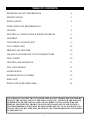
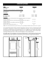
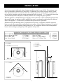
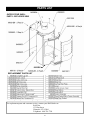
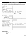
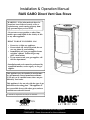
Installation & Operation Manual RAIS GABO Direct Vent Gas Stove WARNING: If the information in these instructions is not followed exactly, a fire or explosion may result causing property damage, personal injury or loss of life. - Do not store or use gasoline or other flammable vapors and liquids in the vicinity of this or any other appliance. - WHAT TO DO IF YOU SMELL GAS • • • • Do not try to light any appliance. Do not touch any electrical switch; do not use any phone in your building. Immediately call your gas supplier from a neighbor’s phone. Follow the gas supplier’s instructions. If you cannot reach your gas supplier, call the fire department. - Installation and service must be performed by a qualified installer, service agency or the gas supplier. This appliance may be installed in an aftermarket, permanently located manufactured home (USA only) or in a mobile home, where not prohibited by local codes. This appliance is for use only with the type of gas indicated on the rating plate. This appliance is not convertible for use with other gases, unless a certified conversion kit is used. Ce manual est disponsible en Français sur demande. Report # 138-S-09b-5 INSTALLER: Leave this manual with the appliance. CONSUMER: Retain this manual for future reference. AVERTISSEMENT: Assurez-vous de bien suivre les instructions données dans cette notice pour réduire au minimum le risque d’incindie ou d’explosion ou pour éviter tout dommage matériel, toute blessure ou la mort. - Ne pas entreposer ni utilizer d’essence ni d’autres vapeurs ou liquides inflammables dans le voisinage de cet appareil ou de tout autre appareil. - QUE FAIRE SI VOUS SENTEZ UNE ODEUR DE GAZ: • • • • Ne pas tenter d’allumer d’appareil. Ne touchez à aucan interrupteur. Ne pas vous servir des téléphones se trouvant dans le bâtiment où vous trouvez. Appelez immédiatement votre fournisseur de gaz depuis un voisin. Suivezles instructions du fournisseur. Si vous ne pouvez rejoindre le fournisseur de gaz, appelez le service des incindie. - L’installation et l’entretien doivent être assurés par un installateur ou un service d’entretien qualifié ou par le fournisseur de gaz. Cet appareil peut être installé dans une maison préfabriquée (mobile) déjà installée à demeure si kes règlements locaux le permettent. Attention. Au moment de l’entretien des commandes, étiquetez tous les fils avant de les débrancher. Des erreurs de la câblage peuvent entraîner un fonctionnement inadequate et dangereux. Cet appareil doit être uniquement avec las type de gaz indiqué sur la plaque signalétique. Cet appareil ne peut être converti à d’autres gaz, sauf si une trousse de conversion est utilisée. S’assurer que l’appareil fonctionne adéquatement une fois l’entretien terminé. Ne pas utiliser cet appareils’il a été plongé, meme partiellement, dans l’eau. Appeler un technician qualifié pour inspecter l’appareail et remplacer toute partie du système de commande et toute commande qui a été plongée dans /’eau. AVERTISSEMENT. Ne pas utiliser l’appareil si le panneau frontal en verre n’est pas en place, est craqué ou brisé. Confiez le remplacement du panneau à un technician agree. INSTALLATEUR: Laissez cette notice avec l’appareil. COMSOMMATEUR: Conservez cette notice pour consultation ultérieur. 2 TABLE OF CONTENTS IMPORTANT SAFETY INFORMATION 4 SPECIFICATIONS 5 INSTALLATION 6 MASSACHUSETTS REQUIREMENTS 7 VENTING 8 ELECTRICAL CONNECTIONS & WIRING DIAGRAM 13 ASSEMBLY 14 CONVERSION TO REAR VENT 17 GAS CONNECTION 18 PRIMARY AIR ADJUSTER 18 AIR INLET AND EXHAUST OUTLET RESTRICTORS 19 FINE-TUNING 20 LIGHTING AND OPERATION 21 FUEL CONVERSION 23 MAINTENANCE 25 MAINTENANCE LOG FORMS 26 PARTS LIST 27 INSTALLATION RECORD FORM 28 WE STRONGLY SUGGEST THAT YOU READ THIS MANUAL THOROUGHLY BEFORE BEGININNG THE INSTALLATION OF THE GABO GAS STOVE. ALTHOUGH THE BASIC REQUIREMENTS FOR THE INSTALLATION OF ALL DIRECT VENT GAS HEATERS ARE SIMILAR, EACH SPECIFIC PRODUCT HAS ITS OWN UNIQUE SET-UP AND INSTALLATION REQUIREMENTS THAT MUST BE FOLLOWED EXACTLY. PLAN YOUR INSTALLATION IN ADVANCE BY CAREFULLY REVIEWING ALL THE INFORMATION CONTAINED IN THIS MANUAL. 3 IMPORTANT SAFETY INFORMATION The installation must conform with local codes or, in the absence of local codes, with the National Fuel Gas Code, ANSI Z223.1 or the Canadian Installation Code, CAN/CGA B149. A manufactured home (USA only) or mobile home OEM installation must conform with the Manufactured Home Construction and Safety Standard, Title 24 CFR, Part 3280 or when such a standard is not applicable, the Standard for Manufactured Home Installations, ANSI/BCSBCS A225.1, or Standard for Gas Equipped Recreational Vehicles and Mobile Housing, CSA Z240.4. The appliance and its appliance main gas valve must be disconnected from the gas supply piping system during any pressure testing of that system at test pressures in excess of 1/2 psi (3.5 kPa). The appliance must be isolated from the gas supply piping system by closing its equipment shutoff valve during any pressure testing of the gas supply piping system at test pressures equal to or less than 1/2 psi (3.5 kPa). The installation must provide for adequate ventilation air to the appliance. This gas appliance must not be connected to a chimney flue serving a separate solid-fuel burning appliance. The appliance, when installed, must be electrically grounded in accordance with local codes, or, in the absence of local codes, with the National Electrical Code ANSI/NFPA 70, or the Canadian Electrical Code, CSA C22. 1. When the appliance is installed directly on carpeting or non-ceramic tile or other combustible material other than wood flooring, the appliance shall be installed on a metal or wood panel extending the full width and depth of the appliance. A commercially available hearth pad meets this requirement. The appliance area must be kept clear and free from combustible materials, gasoline and other flammable vapors and liquids. The flow of combustion and ventilation air must not be obstructed. Do not use this appliance if any part has been under water. Immediately call a qualifed service technician to inspect the appliance and to replace any part of the control system and any gas control which has been under water. Due to high temperatures, the appliance should be located out of traffic and away from furniture and draperies. Children and adults should be alerted to the hazards of high surface temperatures and should stay away to avoid burns or clothing ignition. Young children should be carefully supervised when they are in the same room as the appliance. Clothing or other flammable material should not be placed on or near the appliance. Any screen or guard removed for servicing an appliance must be replaced prior to operating the appliance. Installation and repair should be done by a qualified service person. The appliance should be inspected before use and at least annually by a professional service person. More frequent cleaning may be required due to excessive lint from carpeting, bedding material, etc. It is imperative that the control compartments, burners and circulating air passageways of the appliance be kept clean. WARNING: Do not operate the appliance with the glass door assembly removed, or if the glass is cracked or broken. Replacement of the glass should be done by a qualified service person. WARNING: Use only door assembly, P/N 8303567 which includes the glass panel, frame and gasket. Do not use substitute materials. Do not strike or slam the glass front. Do not use abrasive cleaners. Do not clean when hot. 4 SPECIFICATIONS INPUT Natural Gas Propane (LP) Input Rating-Btu/hr 31,000 31,000 Min. Input-Btu/hr 21,000 22,800 Orifice-DMS 7/64” #52 INPUT (Rear vent, directly though wall to horizontal termination) Input Rating-Btu/hr 25,000 28,000 Min. Input-Btu/hr 18,000 22,000 Orifice-DMS #39 #53 GAS SUPPLY Manifold Pressure 3.5”w.c. / 0.9kPa 10.0”w.c. / 2.5kPa Min. Supply Pressure 4.0”w.c. / 1.0kPa 11.0”w.c. / 2.8kPa Max. Supply Pressure 10.0”w.c. / 2.5kPa 13.0”w.c. / 3.3kPa EFFICIENCY Steady State Efficiency (At Min. Input Rate and Using Minimum Allowable Vent Length)- % Top Vent / Rear Vent 62.8 / 66.2 62.8 / 63.2 Annual Fuel Utilization Efficiency [AFUE](Using Minimum Allowable Vent Length) - % Top Vent / Rear Vent 61.9 / 65.2 61.7 / 62.3 Canadian p.4 Efficiency (Using Minimum Allowable Vent Length)- % Top Vent / Rear Vent 55.5 / 58.1 56.6 / 56.4 Maximum Observed Steady State Efficiency - % 79.7 78.8 NOTE: The maximum achievable steady state efficiency can vary depending the installation and on how the stove is operated. It is recommended that the pilot flame be turned off if the appliance will not be in use for an extended period of time. This appliance is equipped for use with the fuel type indicated on the rating plate. Fuel conversion kits that include the necessary parts and instructions are included with the stove or are available from your installer, dealer or RAIS. This appliance has been certified by OMNI-Test Laboratories, Inc. to ANSI Z21.88-2005 • CSA 2.33-2005 Vented Gas Fireplace Heaters and CAN1-2.17-M91, Gas-Fired Appliances for Use At High Altitudes. The GABO is approved for installation at elevations up to 2000 feet in the U.S. and 1370 meters (4500 feet) in Canada without change. If your installation is at an elevation greater than these, consult with the local authority having jurisdiction for gas product installations to determine their specific requirements for high altitude installations. 18 1/8” (460mm) 20” (508mm) 39 13/16” (1011mm) 6 1/8” (156mm) 34 1/16” (865mm) 5 INSTALLATION Several issues must be addressed when selecting a suitable location for your GABO. The minimum clearances to combustible construction are listed below. In addition, access to the gas supply must be considered. The location of the stove will also affect the venting requirements and you must be certain the location will allow compliance with the venting requirements shown on pages 8 – 13. You must also insure that your installation provides adequate accessibility clearance for servicing and proper operation. When the appliance is installed directly on carpeting or non-ceramic tile or other combustible material other than wood flooring, the appliance shall be installed on a metal or wood panel extending the full width and depth of the appliance. A commercially available hearth pad meets this requirement. Installation and repair should be done by a qualified service person. The appliance should be inspected before use and at least annually by a professional service person. More frequent cleaning may be required due to excessive lint from carpeting, bedding material, etc. It is imperative that the control compartment, burners and circulating air passageways of the appliance be kept clean. MINIMUM CLEARANCES TO COMBUSTIBLE CONSTRUCTION Stove to Left Side Wall 6” (150mm) Stove to Corner Wall Stove to Right Side Wall 6” (150mm) Stove to Ceiling Stove to Rear Wall 2” (51mm) Stove to 12” Deep Mantel Max. Alcove Depth 24” (610mm) Stove to 1½” (38mm) Trim A = 6” (150mm) B = 6” (150mm) C = 2” (51mm) D = 24” (610mm) Max. Alcove Depth 2” (51mm) 35” (890mm) 12” (305mm) 2” (51mm) F = 35” (890mm) G = 12” (305mm) H = 12” (305mm) Max. I = 2” (51mm) C A B D H F ` WALLS I I G E = 2” (51mm) E E CORNER CEILING 6 MANTEL INSTALLATION The gas stove is shipped with a flexible connector that has a 1/2” NPT female connection. The gas supply piping should have a separate gas shutoff valve and a 1/8” NPT plugged tapping upstream of the valve. The stove and its main control valve must be disconnected from the gas supply piping system during any pressure testing of that system at test pressures in excess of 1/2 psi (3.5 kPa). The stove must be isolated from the gas supply piping system by closing the main control valve during any pressure testing of the gas supply system at test pressures equal to or less than 1/2 psi (3.5 kPa). After the gas supply has been connected, use a commercial gas leak detector or apply a soapy water solution to all the fittings to check for gas leaks. Never use a flame to test for leaks. REQUIREMENTS FOR THE COMMONWEALTH OF MASSACHUSETTS This product must be installed by a licensed plumber or gas fitter when installed within the Commonwealth of Massachusetts. If this appliance is installed in a dwelling, building or structure used in whole or in part for residential purposes and the installation includes a horizontal vent termination that is less than seven (7) feet above the finished grade in the area of the venting, including but not limited to decks and porches, a hard-wired carbon monoxide detector with an alarm and battery back-up must be installed on the floor level of the dwelling, building or structure where the appliance is to be installed. Additionally, a hard-wired or battery operated carbon monoxide detector with an alarm must be installed on each additional level of the dwelling, building or structure served by the appliance. It shall be the responsibility of the property owner to secure the services of qualified licensed professionals for the installation of hard-wired carbon monoxide detectors. In the event that the horizontally vented appliance is installed in a crawl space or attic, the hardwired carbon monoxide detector with alarm and battery back-up may be installed on the next adjacent floor level. In the event that this requirement cannot be met at the time of completion of the installation of the appliance, the owner shall have a period of thirty (30) days to comply with the requirement. However, during said thirty (30) day period, a battery operated carbon monoxide detector with alarm must be installed. Each carbon monoxide detector as required in accordance with the above provisions must comply with NFPA 720 and be ANSI/UL 2034 and IAS certified. In addition when the stove is horizontally vented and the vent termination is less than seven (7) feet above finished grade a metal or plastic identification plate must be permanently mounted to the exterior of the building at a minimum height of eight (8) feet above grade directly in line with the exhaust vent terminal. The sign shall read, in print size no less than one-half (1/2) inch in size, “GAS VENT DIRECTLY BELOW. KEEP CLEAR OF ALL OBSTRUCTIONS”. A COPY OF THESE INSTRUCTIONS PLUS ALL VENTING INSTRUCTIONS WHICH INCLUDE PARTS LISTS, AND/OR ALL VENTING DESIGN INSTRUCTIONS MUST REMAIN WITH THE STOVE AT THE COMPLETION OF THE INSTALLATION. ATTENTION INSTALLERS: Mark below which venting system was used in the installation. These instructions must remain with the GABO Installation & Operation Manual. Simpson DuraVent GS® AmeriVent Direct® Selkirk DT® To avoid confusion discard the all vent manufacturers instructions that do not apply to this installation. 7 VENTING The GABO Gas Stove has been tested and listed for installation with 4” X 6 5/8” Simpson DuraVent GS®, AmeriVent Direct® and Selkirk DT® direct venting components. For specific installation requirements, follow the installation instructions included by the venting manufacturer with the venting system components you have chosen. The total vent length may not exceed 36 feet, including vertical rise and horizontal run. The vent lengths are measured from the stove, not the floor. The minimum vertical vent rise when using a vertical vent termination is 10 feet. The minimum vertical rise required when using a horizontal vent termination is 2 feet. The maximum allowed horizontal vent run is 12 feet when the venting includes at least 5 feet of vertical rise. The maximum allowed horizontal vent run for vertical rises of less than 5 feet is shown in the venting charts. No more than three elbows may be used in any installation. The venting charts are set up for installations that use no elbows or that include the use of one elbow. For the second or third elbows that are included in the installation, add 4 feet to the actual horizontal run for each elbow to determine the equivalent horizontal run for the installation. The venting charts allow a simple way to determine the recommended initial settings for both the air inlet restrictor and the exhaust baffle. These settings have been determined by extensive testing and will be a good starting point while setting up the stove. Small adjustments from these settings may be needed to account for specific installation variables. Please see the instructions on pages 19 & 20 for information on how to adjust the restrictors. The numbers (1-7) designate the position of the air inlet restrictor. The higher the number, the greater the restriction. There is a position indicator line on the adjuster handle. When ½ or ¾ is added to the number designation, this indicates that the position is halfway or three-quarters between adjacent numbers. Use the long lines which represent the halfway position between the numbers as a guide. The letters (A-F) indicate the position of the exhaust baffle. The higher the letter, the greater the restriction. Use the top edge of the adjuster handle as the position indicator. When +, ⅛, ¼, ⅜, ½, ⅝, ¾ or ⅞ is added to the letter designation, this indicates that the position is fractionally between adjacent letters. For example, E ⅞ is halfway between E ¾ and F. Use the lines between the letters as a guide. F ⅛ is the first line past F. If F + corresponds to your recommended settings, this is halfway between F and F ⅛. Note: Although some of the recommended settings represent only small incremental differences on the setting indicators, the change in the actual air inlet restrictor or exhaust baffle position is significant. To use the charts, determine the horizontal run length and vertical rise length (in feet) for your installation. If more than one elbow is used, add 4 feet to the actual horizontal run length for each additional elbow to calculate the equivalent horizontal run for the chart. Note: Remember that a maximum of three elbows is allowed. Select the venting chart for the fuel type (Natural Gas or Propane (LP) Gas) and find the box on the chart that corresponds to the vertical rise and actual horizontal run (or equivalent horizontal run, if two or three elbows are used) and read the settings for the inlet air restrictor (1-7) and exhaust baffle (A-F⅛). Examples are shown page 9. Use these as a guide for your particular installation. Note: The GABO is shipped from the factory with inlet air restrictor and exhaust baffle set for 2 feet of vertical rise and 1 foot of horizontal run and for natural gas. The GABO is shipped with a Simpson DuraVent GS® starter section that is specifically designed for the GABO. Regardless of the venting brand you chose, you must use the DuraVent starter section that was provided with your stove. All of the venting brands listed for use with the GABO are compatible with the provided starter section. For venting system installation details, refer to the instructions provided with the venting system you have chosen. Each brand has specific installation requirements that must be followed to insure a safe and functional venting system for your GABO. SEE PAGE 13 FOR INFORMATION ABOUT REAR VENTING DIRECTLY THROUGH THE WALL TO A HORIZONTAL VENT TERMINATION. 8 VENTING Example 1 Fuel = Propane (LP) Vertical Rise = 22 feet Horizontal Run = 3 feet Elbows = 3 Equivalent Horizontal Run = (3 + 4(Elbow 2) + 4(Elbow 3)) = 11 feet Air Restrictor Setting = 3 ¾ Exhaust Baffle Setting = F + Example 2 Fuel = Natural Gas Vertical Rise = 10 feet Horizontal Run = 5 feet Elbows = 1 Equiv. Horizontal Run = 5 feet Air Restrictor Setting = 3 Exhaust Baffle Setting = F Example 3 Fuel = Propane (LP) Vertical Rise = 23 feet Horizontal Run = 0 feet Elbows = 0 Equiv. Horizontal Run = 0 feet Air Restrictor Setting = 3 ¾ Exhaust Baffle Setting = F ⅛ Example 4 Fuel = Natural Gas Vertical Rise = 4 feet Horizontal Run = 6 feet Elbows = 1 Equiv. Horizontal Run = 6 feet Air Restrictor Setting = 2 Exhaust Baffle Setting = D ¾ EXHAUST BAFFLE 3¾ F+ AIR INLET EXHAUST BAFFLE EXHAUST F 3 AIR INLET EXHAUST BAFFLE AIR INLET F⅛ 3¾ EXHAUST BAFFLE D¾ AIR INLET 2 9 VENTING 4½-F⅛ NATURAL GAS VENTING VENTING NOT ALLOWED 4-F⅛ ⅛ 3½-F+ 3 ¾ -F 3¾-F+ 3½-F+ 4-F+ VERTICAL RISE IN FEET 3¾-F⅛ 3-F+ 3½-F+ 3½-F 3½-E⅞ 3½-F 3 ½ -F 2½-F 3-F 3-E⅞ 2½-E¾ 2½-E⅝ 2½-E⅝ 2½-E½ 2½-E 2½-E 1-D 2½-E¼ 2½-E¼ 2½ - E½ 2½ - D¾ 2 -D¾ 1½-D½ 1 - C½ 2½-E⅞ 3½-E¾ 2½-E⅞ 2½ - E¾ 3-F 1-D 2½-E 2½-E¾ 1½-D 1-C 1-A VENTING NOT ALLOWED HORIZONTAL RUN IN FEET 10 VENTING PROPANE (LP) GAS VENTING VENTING NOT ALLOWED 4-F⅛ 3¾-F⅛ VERTICAL RISE IN FEET 3½-F⅛ 3¾-F+ 3¾-F+ 3½-F+ 3¼-F+ 3¾-F 3½-F 3¼-F 3½-F 3¾-F 3½-E⅞ 3¾-E⅞ 3½-E⅞ 3½-F 3-E⅞ ⅞ 3½ - F 3-E¾ 3-E⅝ 3 -E 3½-E¾ 3-E¾ 3-E⅝ 3-E⅝ 2½-E½ 2½-E¼ 2½-E 1½-D½ 1½-D¾ 1-D¼ 2½-E⅝ 1-D 2½-E½ 1-A 1-A VENTING NOT ALLOWED HORIZONTAL RUN IN FEET 11 2½-E VENTING PLEASE NOTE: If your specific venting configuration falls in a box in the venting charts (on pages 10 & 11) that is above the dotted line ( ), you must use one of the approved direct vent venting systems that utilizes a stainless steel inner liner. This requirement is part of the ANSI standards and is based on testing conducted to determine where the exhaust gas temperature drops to the point where condensation might occur in the vent pipe. The standards require the use of corrosion resistant liner materials if that specific total vent length is exceeded. REAR VENTING DIRECTLY THROUGH THE WALL TO A STANDARD HORIZONTAL VENT TERMINATION The Gabo Gas Stove can be vented in rear exit with up to 18” of horizontal pipe (and no vertical pipe) utilizing a standard horizontal vent termination. However, in order for the stove to operate properly, the gas input rate to the stove must be reduced by down-sizing the main fuel orifice that came installed in the stove. The replacement orifices for this purpose are shipped with the stove or are available from your RAIS dealer. The Gabo is shipped from the factory set up to burn natural gas. If you are burning natural gas, replace the standard orifice with the #39 orifice following the instructions on page 23. If you will be burning propane, install the #53 orifice when the fuel conversion is done. Refer to pages 23 & 24. For either fuel, the inlet air restrictor and exhaust outlet baffle should be set at their full open positions to minimize flow resistance. This corresponds to a setting of 1 for the air inlet setting and A for the exhaust baffle setting. Please note: It is highly recommended that a 14” snorkel vent termination be used for this type of installation. Including a 14” snorkel can reduce the variability in performance that can occur due to the low draft associated with this type of installation. Also note: If a 36” snorkel vent termination is used, the gas input rate to the stove does not have to be reduced. To determine the appropriate air inlet restrictor and exhaust baffle settings if using a 36” snorkel, refer to the venting chart settings on pages 10 & 11 for your fuel type and use 3’ for the vertical rise. Use the horizontal run that corresponds most closely to your installation. For up to 12” of horizontal run, use the 1’ box. For 12” to 18” of horizontal run, use the 2’ box. Some fine-tuning from these settings may be desirable. Please refer to page 20 for additional information. 12 VENTING VENT TERMINAL CLEARANCES (Refer to illustration on page 12) Venting terminals shall not be recessed into a wall or siding. ELECTRICAL CONNECTIONS The Gabo Gas Stove may be connected to an optional millivolt thermostat or remote controller. Connect the two wires from the optional thermostat or controller to the terminal block located under the bottom left of the firebox. The wires may go to either terminal. CONTROL WIRING DIAGRAM Caution: Label all wires prior to disconnection when servicing the controls. Wiring errors can cause improper and dangerous operation. Verify proper operation after servicing. 13 ASSEMBLY UNPACKING AND PLACING THE GABO By now, you will have removed the shipping carton from the base pallet. The GABO is shipped in a specially designed shipping carton Cut the strapping that secures the stove to the pallet and remove the wooden cribbing from the top of the stove. Remove the plastic bag that covers the stove. Remove the package of logs and accessories that is packed in the space under the stove and set aside. Lift the stove up and off the pallet. The best place to lift is at the base of firebox. Note: The stove front and the glass frame/glass assembly have to be removed in order to install the logs. Removing them now will reduce the weight and make it easier to lift the stove. Remove transit packing material from between the stove front and the louver and then remove the stove front by lifting it straight up to disengage the keyhole slots from the pins that secure it to the sides. Once it is disengaged, you can move the front away from the stove body. Set the front aside with the back side down to protect the outer surface. With the stove front removed and set aside, remove the glass panel and frame assembly. The latches are located at the top of the door frame. Lift the latch handles up and disengage the latch rods from the slots in the glass frame. Lift the glass and frame assembly up and off the stove and set aside in a safe place. Remove any packing material from inside the firebox. See the two illustrations below. LATCH LOCATIONS The GABO is equipped with leveling bolts to make it easier to install the stove on an irregular surface. The leveling bolts are shipped in the accessory box that was packed in the space under the firebox. Once you have unpacked the leveling bolts, install them in the base plate of the stove. This will require a helper as the stove must be tipped up on the base, first to one side and then the other to allow the leveling bolts to be screwed in from the bottom. For right now, be sure all four leveling bolts are screwed in all the way. They can be adjusted later. See the illustration below for leveling bolt locations. Move the GABO to location where it will be installed. Using as little adjustment as possible for each leveling bolt, adjust them as needed to get the stove as level as possible both side to side and front to back. Once the GABO is in its final location, remove the transit tape from the relief door. The relief door can be identified by the five vertical ribs on its top surface and is located directly adjacent to the glass frame latches on the top of the firebox. This tape must be removed to insure proper operation of the relief door. Also, remove the tie wrap that secures the control access panel during shipping. It is located on the right side of the panel and can be cut with a knife or scissors. The GABO Gas Stove is shipped from the factory equipped to burn natural gas. If you will be burning propane (LP) gas you must convert the stove by replacing the burner orifice and valve regulator and adjusting the pilot fuel selector plate and primary burner air setting. This should be done before the stove is set up. Follow the instructions on pages 23 & 24. LEVELING BOLTS 14 ASSEMBLY LOGS AND EMBERS Carefully unpack each of the three logs and the ember chunk from the log and accessory box. The logs and ember chunk are somewhat fragile and will not survive being dropped from any significant height. If you haven’t already done so, remove any protective cover material from the top of the burner. Each of the three logs is unique and must be placed in a precise location on top of the burner. The burner and log system is designed to facilitate correct placement of the logs. Flat recessed areas on the burner top are keyed to each of the main logs. See the adjacent illustration. Place the arched log first. There is recessed area in the left front corner of the burner top as well as right rear corner. The charred area on the log faces the front of the stove. When correctly positioned, the log will sit firmly in place without tipping or rocking. The arched log has two sockets for the ceramic pins that are included with the log set. These pins locate the left and right cross logs. Place the pins in the sockets. Refer to the illustration below. Place the right cross log next. Use the recessed area at the front right corner of the burner top that corresponds to the shape of the base of the cross log. Place the charred end of the log in the recess and guide the alignment pin hole in the underside of the log onto the rear alignment pin in the arch log. The adjacent illustration shows the proper positions for the first two logs. 15 ASSEMBLY Place the left cross log next. Use the raised platform at the left rear corner of the burner top to support the end of the cross log. The split charred end of the log faces toward the front. Place the pin socket over the front alignment pin hole in the arch log. You may have to wiggle the arch log and right cross log to get the pin socket to drop over the alignment pin. See the adjacent illustration. Finally, place the ember chunk with the noncharred end in the corresponding recess in the burner top per the adjacent illustration. It has a specific position and orientation and will not rock when in the proper position. When correctly placed, the logs and ember chunk will look like the illustration below. 16 ASSEMBLY After the logs and embers have been placed, the next step is to replace the glass panel and frame. Carefully pick up the glass and glass frame assembly by grasping the sides of the frame and using your thumbs and fingers to hold the glass in place within the gasket and frame. With the glass frame (and glass) at a slight angle (leaving room for your fingers between the frame and the firebox) insert the bottom edge of the frame into the frame retainers located on the bottom front of the firebox. Take care to center the frame from left to right. Once the bottom edge is in place, move your fingers out of the way and press the top of the frame against the firebox while pushing down to be sure the frame is fully engaged in the frame retainers. Hold the frame in place with one hand and engage the two glass frame latches by lifting and aligning latch pins into the slots in the top of the frame. Push the latch handles back and down until they are parallel with the top of the firebox, similar to the action of a ski boot buckle. See the adjacent illustration. Top or Rear Vent The GABO has provisions for either top or rear venting but is shipped from the factory set-up for top venting. The rear position is sealed with a special cover plate. If your installation requires rear-venting, you will need to reverse the positions of the starter secSTARTER SECTION tion and the cover plate. First, remove the top plate of the stove by unscrewing the four decorative top retaining bolts. With the bolts removed, lift the top up and off the stove body and set aside. Remove the four screws that secure the vent starter section flange to the firebox top and remove the starter. There are two ceramic fiber gaskets that seal the starter to the stove. These gaskets are very important! Take care in handling these gaskets as they will be re-used. They are somewhat fragile and will tear if handled roughly. See the adjacent illustration. OUTER GASKETS Next, remove the stove back plate from the stove. First remove the two screws at the top of the back that secure the back plate to the back plate bracket. Next lift the back plate up to disengage it from the three slots in the stove base plate. While taking care not to pull on the wiring harness, rotate the back plate away from the back of the stove. Refer to the illustration on page 18. Next break out the rear exit cover plate from the rear plate. INNER GASKETS COVER PLATE Remove the vent cover plate from the rear of the stove following the same procedure as the starter again taking care with the gaskets. Install the cover plate on the top vent opening by reversing the removal procedure. Be sure that the inner and outer gaskets are in their proper positions. 17 ASSEMBLY Install and tighten the four screws. Finally, install the vent starter section in the rear vent position. Again, make sure that the inner and outer gaskets are in their proper positions and install and tighten the four screws. Replace the stove back plate by aligning the rear vent cut-out over the vent starter pipe. Next align the three tabs on the bottom of the back plate with the corresponding slots in the stove base plate. If the fit is tight, work from one side to the other, engaging the tabs sequentially. Once the tabs are engaged, re-install the two fasteners that secure the top of the back plate. KNOCKOUT Reinstall the top plate using the four decorative fasteners. A filler plate is provided for the vent cut-out in the top plate. The filler plate is located in the accessory box that was included with the stove. Once you have re-installed the top plate, simply drop the filler plate in place. LIFT THEN ROTATE BACK PLATE GAS CONNECTION The GABO is shipped from the factory with a flexible gas connector that has a 1/2” NPT female connection. The gas supply piping should have a separate gas shut-off valve and a 1/8” NPT plugged tapping upstream of the valve. The GABO and its inlet regulator and main burner valve must be disconnected from the gas supply piping system during any pressure testing of that system at test pressures in excess of 1/2 psi (3.5kPa). The GABO must be isolated from the gas supply piping system by closing the main control valve during any pressure testing of the gas supply system at test pressures equal to or less than 1/2 psi (3.5kPa). After the gas supply has been connected, use a commercial gas leak detector or apply a soapy water solution to all the fittings to check for gas leaks. Never use a flame to test for leaks. PRIMARY AIR ADJUSTER Your GABO gas stove was shipped from the factory equipped for use with natural gas and the primary burner air adjuster was set at the factory at the recommended position fully closed position for that fuel. However, it is a good idea to confirm that the position is correctly set. The fully-closed position corresponds to the adjuster screw turned in fully. If you will be using propane (LPG) for your installation, please see the instructions for fuel conversion on pages 23 & 24 of this manual. This includes instructions for the proper setting for the primary air adjuster. See the illustration below for the location of the primary air adjuster screw. Making small adjustments to the primary air setting will let you adjust the way the flames PRIMARY AIR look for your particular installation. See the ADJUSTER SCREW reference to primary air adjustment in the sections on page 20 that explains fine-tuning. 18 ASSEMBLY AIR INLET AND EXHAUST OUTLET RESTRICTORS The GABO is equipped with externally adjustable restrictors for both the inlet air and the exhaust outlet. This makes it possible to fine tune the direct vent system for the specific conditions of your installation. The recommended settings are keyed to the specific details of your venting configuration. To access the restrictor adjustment guide plates, you must first remove the front air louver from the stove. To do this, first loosen the four decorative fasteners that secure the stove top. These do not have to be fully removed but must be loose enough that the front of the top can be lifted up slightly. The louver assembly is held in place by pins that are keyed to special slots in the sides of the stove. Grasp the louver assembly firmly. Note: The louver is quite heavy so get a good grip on it. Pull the louver forward and lift the louver up until it disengages from its retainer pins. The stove top may have to lifted slightly to allow room for the louver to disengage from the stove. Having a second person lift the front edge of the top may be helpful since the top is quite heavy. Once the louver disengages, slide it forward to remove it and set it aside. This will now give you access to the restrictor guide plates and locking wingnuts. LOUVER RETAINER SLOT LOUVER RETAINER PIN You will now see the two guide plates. The guide plates have a pointer that corresponds to a number scale for the air adjustment and letter scale for the exhaust adjustment. These are the letters and numbers that are referenced in the venting charts on pages 10 and 11 and shown in detail in the examples shown on pages 8 and 9. To change the setting, loosen the guide plate locking wingnuts. Next rotate each guide plate to the recommended setting for your installation shown in the appropriate venting chart for natural gas or for propane (LP) gas. Once the settings are correct, tighten the locking wingnuts. EXHAUST RESTRICTOR GUIDE PLATE LOCKING WINGNUT LOCKING WINGNUT INLET AIR RESTRICTOR GUIDE PLATE 19 FINE-TUNING Fine-Tuning The recommended settings found in the vent charts on pages 10 & 11 and the default primary air settings have been optimized based on extensive testing, however, additional adjustments may be required to accommodate specific installation circumstances. For example, a north wall installation may require slightly different settings than a south wall. Fine-tuning can be accomplished with the stove installed and operating. Please take care not to burn yourself on any of the hot surfaces. Always wear gloves and other protective equipment. The stove front and louver should still be removed at this point allowing the two adjuster mechanisms to be accessed. The settings for each can be adjusted from the recommended settings while you are watching the fire in the stove. It is important that the fine-tune adjustments are made only after the stove is thoroughly heated so allow the stove to burn for at least 20-30 minutes at high fire while observing the flame. The type of adjustments that you might try are somewhat dependent on the type of fuel that is being used. When burning natural gas, flames that are too short or too blue will be the most common observation. When burning propane, flames that are too long and too sooty will be most common. Each situation requires different actions. If you are burning natural gas and observe that the flames are short and blue: First, check the position of the primary burner air adjuster. The adjuster screw is located on the bottom of the firebox near the valve. For natural gas, the primary air adjuster should be in the fully-closed position. If it is not, loosen the adjuster screw locknut and turn the adjuster screw in until it stops. If the appearance of the fire does not change, you may need to adjust the air inlet restrictor. Be careful as the stove surfaces are HOT! Loosen the air inlet restrictor indicator plate locking wingnut and move the setting up in ¼ increments. For example, move the setting from 2 ¾ to 3. Tighten the locking wingnut and observe the flames. Repeat the process until the flames become taller and more luminescent. However, no more than one full increment of adjustment should be made. If the flames are still too short and blue, next adjust the exhaust baffle setting. Loosen the exhaust baffle indicator plate locking wingnut and move the setting up in ¼ increments. For example, move from a setting of D to a setting of D ¼. Repeat the process until the flames become taller and more luminescent. However, no more than one full increment of adjustment should be made. If no change in the flame appearance is noted after that, there may be an installation problem. Consult with a RAIS representative. If you are burning propane and observe that the flames are tall and sooty: First, check the position of the primary burner air adjuster. For propane, the primary air adjuster should be in the fully-open position. If it is not, loosen the adjuster screw locknut and back out the adjuster screw until it stops. If the appearance of the flame does not change, you may need to adjust the exhaust baffle. This can be done with the stove operating but again, be careful as the stove surfaces are HOT! Loosen the exhaust baffle indicator plate locking wingnut and move the setting down by ¼ increments. For example, move from a setting of E ½ to a setting of E ¼. Tighten the locking wingnut and observe the flames. Repeat the process until flame tips shorten and become lighter in color. However, no more than one full increment of adjustment should be made. If the flames are still too tall and sooty, next adjust the air inlet restrictor setting. Loosen the air inlet restrictor indicator plate locking wingnut and move the setting down in ¼ increments. For example, move the setting from 2 ¾ to 2 ½. Tighten the locking wingnut and observe the flames. Repeat the process until the flames become shorter and more lighter. However, no more than one full increment of adjustment should be made. If no change in the flame appearance is noted after that, there may be an installation problem. Consult with a RAIS representative. Once all adjustments are made, make sure the air inlet and exhaust baffle adjuster plate locking wingnuts are tight. If an adjustment was made to the primary burner air, tighten the locknut on the adjustment screw to lock in the new setting. Shut off the stove and let it cool down. Reinstall the Louver Replace the air louver by aligning the slots on the louver end plates with the louver pins on the stove sides. You may need to lift the top slightly to get “up-and-over” the pins. The louver will drop into place when in the proper position. Tighten the four decorative top fasteners. Reinstall the Stove Front To reinstall the stove front, align the four attachment slots on the door edges with the pins on the stove sides. Push the front in and down to its final position. 20 LIGHTING AND OPERATION LIGHTING THE FIRE FOR YOUR SAFETY READ BEFORE LIGHTING WARNING: If you do not follow these instructions exactly, a fire or explosion may result causing property damage, personal injury or loss of life. A. This appliance has a pilot which must be lighted by hand. When lighting the pilot, follow these instructions exactly. B. BEFORE LIGHTING smell all around the appliance area for gas. Be sure to smell next to the floor because some gas is heavier than air and will settle on the floor. WHAT TO DO IF YOU SMELL GAS • Do not try to light any appliance. • Do not touch any electric switch; do not use any phone in your building. • Immediately call your gas supplier from a neighbor’s phone. Follow the gas supplier’s instructions • If you cannot reach your gas supplier, call the fire department. C. Use only your hand to push in or turn the gas control knob. Never use tools. If the knob will not push in or turn by hand, don’t try to repair it, call a qualified service technician. Force or attempted repair may result in a fire or explosion. D. Do not use this appliance if any part has been under water. Immediately call a qualified service technician to inspect the appliance and to replace any part of the control system and any gas control which has been under water. 1. 2. 3. 4. 5. 6. 7. 8. 9. LIGHTING THE FIRE STOP! Read the safety information above on this label. Set the thermostat to the lowest setting. Turn off all electric power to the appliance. Push in the gas control knob slightly and turn clockwise to “OFF”. NOTE: Knob cannot IN OUT be turned from “PILOT” to “OFF” unless knob is pushed in slightly. KNOB IN “OFF” POSITION Wait five (5) minutes to clear out any gas. Then smell for gas including near the floor. If you smell gas, STOP! Follow “B” in the safety information above on this lable. If you don’t smell gas, go to the next step. Find pilot - Look in the rear center of the firebox. Turn the knob on the gas control counterclockwise to “PILOT”. PILOT Push in the control knob all the way and hold in. Immediately light the pilot by repeatedly pushing the piezo. Continue to to hold the control knob in for about one (1) minute after the pilot is lit. Release knob and it will pop back up. Pilot should remain lit. If it goes out, repeat steps 4 through 8. • If the knob does not pop up when released, stop and immediately call your service technician or gas supplier. • If the pilot will not stay lit after several tries, turn the gas control knob to “OFF” and call your service technician or gas supplier. Turn the gas control knob counterclockwise to “ON”. PI TO TURN OFF GAS TO APPLIANCE 1. Set the thermostat to the lowest setting. 2. Turn off all electric power to the appliance. 3. Push in the gas control knob slightly and turn clockwise to “OFF”. 21 L OT LIGHTING AND OPERATION PILOT AND MAIN BURNER OPERATION Follow the lighting instructions on page 21. When the pilot is lit and operating properly, it should look like the adjacent illus- CORRECT PILOT tration. One flame will be directed at the pilot thermocouple, a FLAMES second flame is directed at the pilot thermopile and the third will be emanating toward the burner. If the pilot flames do not resemble the illustration above, see the instructions below for pilot flame adjustment. After the main burner ignites and has been in operation for a few minutes, the flames should look like those in the illustration below. Note: Flame height will vary depending on the firing rate but flames should be burning in all of the areas seen in the illustration. PILOT FLAME ADJUSTMENT The pilot flow is factory set to maximum. The pilot flame should envelope 3/8” to 1/2” of the thermocouple and thermopile. See the illustration at the top of this page. If the pilot flames do not resemble those shown in the illustration, the pilot flame may be adjusted. 1. Locate the pilot adjustment screw on the valve referring the adjacent illustration. 2. Turn the adjustment screw clockwise to decrease or counterclockwise to increase pilot flame. 22 PILOT FLAME ADJUSTMENT SCREW VALVE REGULATOR FUEL CONVERSION The GABO Gas Stove is shipped from the factory equipped to burn natural gas. If you will be burning propane (LP) gas you must convert the stove by replacing the burner orifice and valve regulator and adjusting the pilot fuel selector plate and primary burner air setting. This should be done before the stove is set up. Follow the instructions on page 14 for removing the stove front and glass/glass frame assembly from the stove. If the logs are in place on the burner, remove them and set them aside in a safe location. Burner Orifice Locate the burner hold down bolt. It is located on the underside of the firebox above the valve. Open the control access door by pulling forward and rotating BURNER HOLD DOWN BOLT down. See the adjacent illustration for help in determining the hold down bolt location. Using a 7/16” wrench, remove the bolt and set aside. Pick the left end of the burner assembly up a few inches and then lift the burner straight up to disengage the burner assembly from the primary air adjuster system. The burner assembly is somewhat heavy so take care in handling. Set the burner assembly aside in a safe location to avoid damage. Place an 11/16” open end wrench on the orifice holder fitting to secure it and loosen the orifice using a 9/16” wrench or preferably a deep socket. Set the old orifice aside and install the new orifice. Again, be sure to use a stabiORIFICE HOLDER lizing wrench on the FITTING orifice holder fitting and be sure the orifice is tight in the orifice holder fitting. Note: The orifice holder and orifice are brass components and could break if overtightened Refer to PRIMARY AIR the two adjacent illus- ADJUSTER BOX trations. Primary Air Adjuster The primary air adjuster screw is located under the firebox near the control valve. It is factory set in the fully closed position for natural gas. For propane the proper setting is fully open. Loosen the locknut and back the screw out until you observe the primary air shutter has reached the fully open position. Retighten the locknut. Burner Orifice Installation (when rear-venting directly through the wall) Follow the procedure above for replacing the burner orifice if you are rear venting your stove directly through a wall to a horizontal termination. The proper orifices for this purpose are included with your stove. For natural gas, use the #39 orifice. For propane (LP) gas, use the #53 orifice. Refer to page 12 of this manual for more information. Pilot Orifice The pilot is convertible from one fuel to the other by simply loosening the pilot hex (using a 7/16” open end wrench) and sliding the orifice strip to the correct position for the fuel you are using. Turn the pilot hex 1/4 turn counter-clockwise taking care not to contact the orifice strip or either of the igniter electrode. Refer to the illustrations on page 24. 23 FUEL CONVERSION Pilot Orifice (cont.) Slide the orifice strip from the natural gas position to the LP Gas position. Refer to the illustrations below. Once the pilot strip has been re-positioned, re-tighten the pilot burner barrel and the pilot conversion is complete Note: The pilot burner should align with the thermocouple and thermopile when tightened. TIGHTEN 1/4 TURN LOOSEN 1/4 TURN NOTE: THE ORIFICE STRIP MAY BE RANDOMLY LOCATED ON ANY SIDE OF THE HEX FITTING. Valve Regulator The Hi/Low pressure regulator on the valve must be replaced with the propane (LP) regulator. Refer to the illustration at the bottom of page 22 for the location of the valve regulator. Follow the installation instructions that are included with the propane regulator. Leak Testing After the fuel conversion has been completed, use a commercial gas leak detector or apply a soapy water solution to all the fittings and around the valve regulator and pressure taps to check for gas leaks. Never use a flame to test for leaks. Fuel Conversion Label Finally, using permanent ink, fill in all blank spaces on the fuel conversion label that was included with the stove. This information is very important as this label will supersede the natural gas specified on the permanent rating plate. Apply the label to the rear surface of the control access door where it will be clearly visible after installation. See adjacent illustration of the fuel conversion label. In some circumstances, it may be necessary to convert the stove back to natural gas. Contact your installer or Rais dealer for assistance. Replace the Burner and Complete the Stove Assembly Re-install the burner by positioning it inside the firebox several inches above its final location and lowering the right end down first so that the burner inlet guide engages over the primary air adjuster box. From the proper angle, you can look under the burner as you lower it down (a flashlight may be helpful). Once the burner inlet is properly engaged in the primary air adjuster box, lower the left side down. The burner will sit flat in the stove when properly position. A second guide on the floor of the firebox insures that the burner hold down bracket is in the proper alignment for the burner hold down bolt. Re-install the burner hold down bolt. If the burner is properly positioned, the hold down bolt should thread in without causing movement of the burner. Follow the instructions on that begin on page 14 of this manual to complete the assembly and installation of your GABO. 24 MAINTENANCE A qualified service agency should conduct an annual inspection and maintenance of your GABO including the overall installation and venting to keep it running safely. The following procedures should be performed only by a qualified service person. The gas supply should be turned off and the stove should be completely cool whenever a maintenance procedure is performed. All parts of the appliance that are removed for servicing must be replaced prior to operation. WARNING: Do not operate the appliance with the glass front removed, cracked or broken. Replacement of the glass should be done by a qualified service person. WARNING: Use only door assembly, P/N 8303567 which includes the glass panel, frame and gasket. Do not use substitute materials. Do not strike or slam the glass front. REPLACING THE GLASS The glass mounting system consists of the glass panel, special glass gasket and the metal glass frame. Should the glass need to be replaced, you must replace the entire glass/glass frame assembly that can be obtained from your authorized RAIS dealer. Use the following procedure and refer to the illustrations on pages 14 and 17 of this manual. 1. Turn the stove completely off and allow it to cool completely. 2. Remove the Stove Front. See instructions on page 14. 3. If the glass is broken, be sure to wear gloves and eye protection. 4. Unlatch the two glass frame latches by pulling up and forward on the latch finger handles. Disengage the latch rods from the slots in the glass frame. This will allow the glass frame to tip slightly forward. The glass may be loose in the frame, so it is very important to support both the glass and the frame when handling. Place your thumbs on the outside of the glass frame and wrap your fingers around the frame and onto the glass. Squeeze the frame and glass while moving. Carefully lift the glass frame and glass up and off the stove. Set the glass and frame aside on a padded surface. If the glass is broken, do this over spread out newspaper to catch all loose material. Wrap the old glass frame, glass and gasket in several layers of newspaper and discard. Installing the replacement glass/glass frame assembly. 1. Unpack the new glass/glass frame assembly taking care when handling. 2. Carefully pick up the glass and glass frame assembly by grasping the sides of the frame and using your thumbs and fingers to hold the glass in place within the gasket and frame. 3. With the glass frame (and glass) at a slight angle (leaving room for your fingers between the frame and the firebox) insert the bottom edge of the frame into the frame retainer located on the bottom front of the firebox. Take care to center the frame from left to right. Once the bottom edge is in place, move your fingers out of the way and press the top of the frame against the firebox while pushing down to be sure the frame is fully engaged in the frame retainer. Hold the frame in place with one hand and engage the two glass frame latch rods. 4. Push the latch handles back and down until the handles are parallel with the top of the firebox. 5. Replace the Stove Front. See instructions on page 20. CLEANING THE GLASS WARNING: Never clean the glass while it is hot. Do not use abrasive cleaners or cleaners containing ammonia. NOTE: A micro-fiber cleaning cloth and plain water is recommended by the glass manufacturer. . 25 MAINTENANCE INSPECTING THE VENTING An inspection of both the inner and outer vent pipes and the vent terminal should be made as part of the annual service appointment. The venting must have no blockage and be in good repair. The vent manufacturer’s instructions may provide specific details on vent inspection. Any vent sections that are disassembled must be reassembled and sealed as required. This appliance should be inspected before use and at least annually by a qualified service person. More frequent cleaning may be required due to excessive dust or lint from carpeting, bedding materials, pets, etc. It is imperative that control compartments and circulating air passageways of this appliance be kept clean. CLEANING THE LOGS, BURNER AND FIREBOX During the annual inspection and maintenance appointment, the service person should clean the logs, burner and firebox. To gain access to the firebox, logs and burner, follow the instructions beginning on page 14 of this manual. An extra-soft brush should be used to gently clean the logs and burner as they are extremely fragile. DO NOT USE A VACUUM CLEANER TO CLEAN THE LOGS OR BURNER. A vacuum cleaner may be used to clean the metal parts of the firebox. Replace the logs and embers after cleaning. Follow the instructions on pages 15-16 of this manual to insure proper placement of the logs and ember chunk on the burner. AIR FLOW The GABO utilizes a convection air heat exchange system to maximize heat delivered from the stove. It is important that air flows freely through the convection air system and out the front and side air grills. Do not place objects under the stove that will block the convection air inlet flow or in front of any air outlet. MAINTENANCE LOG Date of Service ____________________ Serviced By ______________________ Service Performed Inspect Venting Clean Burner, Logs & Firebox Clean Control Area Clean Convection Air System Leak Test Gas Connections Other __________________________ Date of Service ____________________ Serviced By ______________________ Service Performed Inspect Venting Clean Burner, Logs & Firebox Clean Control Area Clean Convection Air System Leak Test Gas Connections Other __________________________ Date of Service ____________________ Serviced By ______________________ Service Performed Inspect Venting Clean Burner, Logs & Firebox Clean Control Area Clean Convection Air System Leak Test Gas Connections Other __________________________ Date of Service ____________________ Serviced By ______________________ Service Performed Inspect Venting Clean Burner, Logs & Firebox Clean Control Area Clean Convection Air System Leak Test Gas Connections Other __________________________ 26 PARTS LIST OUTER STOVE SHELL PARTS - EXPLODED VIEW 8303505 REPLACEMENT PARTS LIST *This is a quick response thermocouple. Replace it only with Part No. 8303565 For replacement parts and customer service, contact your RAIS dealer or: RAIS Inc. 133 Elm Street Winooski, VT 05404 Telephone: 888-724-7789 27 INSTALLATION RECORD The installer should complete the form below that describes the details of the installation. Having this written record of installation information available will greatly expedite trouble-shooting should any problem arise with your stove. The installer should keep a duplicate of this form for their records. Manufactured by: RAIS a/s Industrivej 20 DK-9900 Frederikshavn Denmark www.rais.com 28 V05/06.07