1
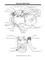
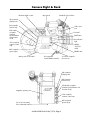
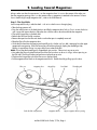
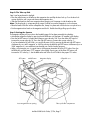
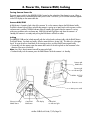
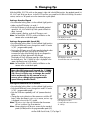
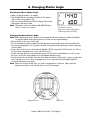
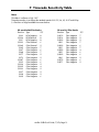
535B Quick Guide
Customer Support Information .........................................2
Camera Left & Front........................................................3
Camera Right & Back .....................................................4
1.
2.
3.
4.
5.
6.
7.
Quick Specs.................................................5
Loading Coaxial Magazines ........................6
Threading ...................................................8
Power On, Camera RUN, Inching...............10
Changing Fps ............................................11
Changing Shutter Angle.............................12
Timecode Sensitivity Table .........................13
7/97a
Customer Support
If you have a question or problem, please contact one of our offices at the following addresses. In the case
of inquiries or when ordering parts, please refer to the camera model and serial number.
Arriflex Corporation, East Coast
617 Route 303, Blauvelt, NY 10913-1109
Voice phone:
914-353-1400
FAX:
914-425-1250
Email:
[email protected]
Website:
http://www.arri.com
Arriflex Corporation, West Coast
600 North Victory Blvd., Burbank, CA 91502-1639
Voice phone:
818-841-7070
FAX:
818-848-4028
About This Quick Guide
If you are viewing the Adobe Acrobat version of this Quick Guide, best viewing and printing results can be
achieved through the use of the Acrobat Reader version 3.0 or later. The Acrobat Reader can be
downloaded for free from the Adobe web site at http://www.adobe.com.
Safety Specifications
• When transporting the camera, make sure that the sliding door securing the field lens is all the way down.
• In order to ensure optimal performance, it is essential that you acquaint yourself with this Quick Guide
and that you follow the operating instructions described herein. We strongly recommend that you also
acquaint yourself with the full 535B instruction manual.
• Assembly and initial operation should only be carried out after carefully reading the instructions and
familiarizing yourself with the equipment and the assembly procedures!
• Use only original ARRI accessories and replacement parts!
• Clean optical surfaces only with an optical brush or a clean optical cloth! In cases of solid dirt, moisten an
optical cloth with pure alcohol (or brand-name lens cleaner).
• Do not use solvents when cleaning the film path!
• When adjusting the mirror shutter, turn the camera off and remove the power cable. Accidentally running
the camera while adjusting the mirror shutter can cause great damage.
• Do not unscrew any screws which are sealed with locking paint!
• Never run the camera without a lens or a protective cap in the lens mount receptacle.
• Never place your hand in the lens cavity or the inside of the camera while the camera is running!
• Never open the movement or gate locking mechanism while the camera is running!
Arriflex 535B Quick Guide, 7/97a, Page 2
Camera Left & Front
Receptacle for heated eyecup cable
Arriglow brightness adjustment
Eyecup
Contrast filter lever
Eyepiece
Safety button for finder turret
Release lever for finder turret
Eyepiece lock
Magazine display
(Electronic footage counter)
Door lock safety
button
Magazine
door lock
Run button
Electronic inching/
PHASE button
400 foot magazine
Locking slider
LCD display
Run indicator light
Camera door lock
MODE button
SEL button
SET button
Image rotation knob
Bubble level
Friction adjustment
Image rotation release
Viewfinder
PL mount
Mirror shutter
Viewfinder extension lock
Arriflex 535B Quick Guide, 7/97a, Page 3
Camera Right & Back
Mechanical film counter
Grip System
Viewfinder swivel release
DU receptacle
(display unit)
RU receptacle
(remote unit)
Video assist
port
ESU & MCL
receptacle
(external
synchronization
unit & master
clock)
Dovetail
RUN button
Run indicator
light
CCU receptacle
(camera control
unit)
NORM
- PS/CCU
switch
BAT receptacle
(power input)
PROG button
Main power on/off switch
RS receptacles
(remote RUN & 24 V dc)
12 V ACC receptacle
(accessories)
DU receptacle
(display unit)
RU receptacle
(remote unit)
ESU & MCL receptacle
(external synchronization unit
& master clock)
Magazine opening cover
CCU receptacle
(camera control unit)
BAT receptacle
(power input)
Two 3/8-16 mounting
holes underneath camera
Arriflex 535B Quick Guide, 7/97a, Page 4
1. Quick Specs
Fps range:
3.000 to 60.000 fps, forward and reverse
Mirror shutter:
15.0° to 180.0°, manually adjustable
Fixed settings at: every 15° from 15° to 135° and 144°, 172.8° and 180°
Power:
BAT:
24 V dc, Fischer connector, pin #1 is negative, pin #2 is positive
Acceptable voltage range: 20 to 32 V dc
RS:
Pin #1 is GND, pin #2 is +24V dc, pin #3 is /E-Run
Power output: 24 V dc, 1 amp max.
12 V ACC:
Pin #9 is GND, pin #11 is +12 V dc
Power output: 12 V dc, 1.8 amps max.
CCU:
Pin #4 is GND, pin #3 is +24 V dc
Power output: 24 volts dc, 0.4 amps max.
Fuses:
Main fuse: .................15 A Picofuse
Located on the left side of the electronics cover. The main
fuse can only be accessed when the magazine is removed.
Magazine fuse F1: .....3 A Picofuse
Magazine fuse F2: .....0.25 A Picofuse
Located underneath a cover in the magazine throat.
Movement:
Two pull-down film transport claws and two registration pins
Flange focal distance: 51.98 - 51.97 mm
Temperature range:
-4° Fahrenheit to +122° Fahrenheit (-20°Celsius to +50°Celsius)
Viewfinder Indicators: END blinking: Film end coming up in X feet (“X” can bet set by user)
END:
Camera ran out of film
ASY:
Asynchronous camera operation
BAT:
Low battery (less than 20 volts). Exchange battery.
Display Indicators:
TC
TC blinking
bat
asy
end blinking
end
fps blinking
Timecode is turned on
Timecode is turned on, but not recording properly
Low battery (less than 20 volts). Exchange battery.
Asynchronous camera operation
Film end coming up in X feet (“X” can be set by user)
Camera ran out of film
ESU is not receiving a valid signal
Display Warnings:
The LCD Display will indicate any situations that will prevent running the
camera by changing one or more of its digits into underlines.
Magazine improperly attached
ft
fps
Movement block
not locked
Magazine not ready
Magazine
communications check
0 0 0 0
0 0 _ 0
Film jam in upper Sprocket guides
loop area
are open
Arriflex 535B Quick Guide, 7/97a, Page 5
Film jam in lower loop
area, or film end
2. Loading Coaxial Magazines
Always make sure that a loop protector is on the magazine when it is not on the camera. Also make sure
that the magazine opening cover is on the camera when no magazine is attached to the camera. To learn
how to load the light weight magazine LM-1, refer to the 535B manual.
Step 1: The Feed Side
Load unexposed film only in absolute dark - such as in a dark room or changing bag.
• Take the loop protector off.
• Press the safety button on the feed side door and flip the magazine door lock up. Turn it counter clockwise
until it stops and remove the door. Place the door with the interior face down beside the magazine.
• Flip up the hinged clip on the feed shaft.
• Remove the film from the film container.
• Remove the tape from the film end. Make sure that the tape is completely removed.
• Place the film roll on the magazine door.
• Guide the film head into the opening and carefully push it further until you feel it emerging from the upper
magazine throat opening. If the film cannot be pushed through easily, employ the threading aid by
flipping it up and then turning it counter clockwise to advance the film.
Note: Ensure that the threading aid is flipped back into position. Otherwise it can cause noise.
• Now place the film on the feed shaft and push the film core down as far as it will go, without pressing on
the film itself. The film will otherwise become conical and cause noise.
• Flip down the hinged clip to lock the film core on the feed shaft.
• Put the magazine door back on the magazine and lock it. Double check by pulling up on the door.
Film core
Magazine door
Feed side film compartment
Hinged clip
Magazine throat
Feed shaft
Threading aid
Upper magazine throat opening
Arriflex 535B Quick Guide, 7/97a, Page 6
Step 2: The Take-up Side
Step 2 can be performed in daylight.
• Press the safety button on the take-up side magazine door and flip the door lock up. Turn the door lock
counter clockwise until it stops and remove the magazine door.
• Slide the film head into the lower magazine throat opening until it emerges inside the take-up side.
Note: The loop-length is unimportant at this stage. It will be set once the magazine is on the camera.
• Place the head of the film into the collapsible core, clamp it in place and wind clockwise a couple of turns.
• Put the magazine door back on the magazine and lock it. Double check by pulling up on the door.
Step 3: Setting the Counter
The magazine display will count down the loaded footage if it has been entered during loading.
• Activate the magazine display by pressing the MODE button until the letters "ft" appear in the display.
• Press the left SET button to increase the footage counter value by 100'. Press the center SET button to
increase the counter value by 10'. Press the right SET button to increase the counter value by 1'.
If you have loaded a full roll of film, you can quickly enter 393' by pressing the left and right SET buttons
simultaneously on a 400' magazine, or 983' by pressing the left and right SET buttons simultaneously on a
1000' magazine. It is assumed that some footage was used for loading purposes.
• When using timecode, now is a good time to set the proper timecode sensitivity (TCS) value. Press the
MODE button until the letters "TCS" appear in the display. Pressing any of the three SET buttons will
increase the TCS value by 1. See the table at the end of the Quick Guide for the proper TCS values.
SET buttons
MODE button
Lower magazine throat opening
Magazine display
Collapsible core
Take-up side film compartment
Arriflex 535B Quick Guide, 7/97a, Page 7
3. Threading
Mounting the Magazine
Attaching a magazine to the camera and threading film is done in the same manner with the coaxial and
with the lightweight magazines.
Note: On the 535B the movement block is disengaged from the drive system when it is swung away
from the gate. Both the movement and the drive system can now be turned independently of each other.
The movement block cannot be returned to the front position if either one has been moved. To return to
the proper coupling position, slowly turn the knurled discs on the sprocket rollers without pushing them
in, until the movement block will swing forward freely.
Attaching the Magazine to the Camera
• Open the camera door and remove the magazine opening cover.
• Turn the inching knob on the movement until the white index line aligns with the LOADING POSITION line.
• Push the movement locking lever to the UNLOCK position and swing the movement block away from the
film gate.
• Turn the sprocket guide lever up, towards the OPEN position.
• Pull some film out of the magazine until the loop is about 1 foot long.
• Push the loaded magazine halfway into the dovetail guide on the camera.
• Place the film in the movement so that it lies between the sprocket guides and the sprocket rollers, and
between the movement and the film gate (see graphic on the next page).
• Push the magazine into the camera as far as it will go. The magazine will lock with an audible click.
Upper sprocket guide
Knurled disc
Sprocket roller
Film gate
Sprocket guide lever
Movement locking lever
Movement
Sprocket roller
Inching knob
Knurled disc
Magazine lock
Lower sprocket guide
Arriflex 535B Quick Guide, 7/97a, Page 8
Threading the Film
• Position the film on the upper and lower sprocket rollers so that the sprockets engage the film perforations.
Gravity will hold the film in place on the lower sprocket roller, but you may have to lift the upper film loop
a little to hold the film on the upper sprocket roller. Close the sprocket roller guides by turning the sprocket
guide lever towards the CLOSED position.
Note: If you cannot easily close the sprocket guide lever, it is an indication that the sprockets do not engage
the film perforation properly. Open the sprocket guide lever again and reposition the film. Never
force the sprocket guide lever!
• The white index line on the inching knob should still align with the LOADING POSITION on the movement.
• Push the movement locking lever to the UNLOCK position and gently swing the movement forward towards
the film gate. Simultaneously slide the film a little up and down to ensure that the transport claws engage
the film perforations.
• Set the upper and lower film loop to the corresponding film loop markings by pushing down on the
knurled discs and turning them.
• To check for proper film transport, turn the inching knob in the direction of the arrow on the movement
(clockwise). Alternatively, you can push the PHASE button to electronically inch the camera.
Upper film loop marking
Knurled disc
Upper sprocket roller
Sprocket guide lever
Movement locking lever
Movement
Inching knob
Lower film loop marking
Knurled disc
Arriflex 535B Quick Guide, 7/97a, Page 9
Lower sprocket roller
4. Power On, Camera RUN, Inching
Turning Camera Power On
The main power switch for the ARRIFLEX 535B is located on the underside of the electronics cover. When a
battery is attached to the camera and the main power switch is turned on, you should see characters appear
on the LCD display on the camera left side.
Camera RUN/STOP
A RUN button is located on both sides of the camera. To run the camera, depress the RUN button briefly.
The RUN indicator light will glow red while the camera is coming up to speed, and switch to green once the
set frame rate is reached. The RUN indicator light will steadily glow green when the camera is running
without any problems at the set frame rate. If the RUN indicator light glows red when the camera is in
Standby, the camera is not ready and pushing the RUN button will have no effect.
Inching
The ARRIFLEX 535B can be inched manually with the inching knob or electronically with the PHASE button.
The PHASE button, if pushed very briefly, will also rotate the mirror shutter 180°. This allows for a fast gate
check. To move the mirror shutter back in the viewing position, push the PHASE button again briefly.
• To manually inch the camera, open the camera door and turn the inching knob on the movement in the
direction of the arrow (clockwise).
Note: Any film in the movement area will be exposed to light!
• To electronically inch the camera, press the PHASE button while the camera is in Standby.
Camera right
RUN button
Camera right
run indicator light
NORM - PS/CCU
switch
Electronics cover
Main power switch
Electronic inching/
PHASE button
Camera left
RUN button
LCD display
Camera left
run indicator light
Arriflex 535B Quick Guide, 7/97a, Page 10
5. Changing Fps
With the NORM - PS/CCU switch on the camera's right side in the NORM position, the standard speeds 24,
25, 29.97 and 30 fps can be run. In the PS/CCU position, any speed from 3.000 to 60.000 fps, forward or
reverse, can be run. All speeds set on the camera are crystal speeds.
Setting a Standard Speed
• Ensure that the locking slider is in the unlocked (right) position.
• Make sure the LCD display is in mode 1.
• Push the SEL button to cycle through the available standard
speeds 24, 25, 29.97 and 30 fps. Each speed will flash for
about 3 seconds.
• While a speed is flashing, push the SET button to set it.
Note: Set the NORM - PS/CCU switch to NORM to run the
camera at the set standard speed.
Setting a Programmable Speed (PS)
• Ensure that the locking slider is in the unlocked (right) position.
• Push the MODE button once to change from mode 1 to mode
2 ("PS" - programmable speed).
• Pressing the SEL button now will select one digit after the other.
A selected digit will blink. Pressing the SET button will
increment the value of the blinking digit by one. Repeat this
procedure for all digits that need to be changed.
The display will show full frame speed plus three digits past
the decimal point. The 1/1000 th of a fps is displayed in the
upper right-hand corner of the display.
Note: Set the NORM - PS/CCU switch to NORM to run the
camera at the set standard speed.
LCD display in mode 1.
Current frame rate set at 24 fps.
LCD display in mode 2.
Current frame rate set at 18.325 fps.
Note: One SEL button push beyond the 1/1000th
fps is the setting that allows for reverse running
(cd). Since it is fairly easy to change, be careful
not to accidentally set the camera to run in
reverse when changing the programmable
speed. Always double check!
Setting the Camera to run in Reverse
• Ensure that the locking slider is in the unlocked (right) position.
• Push the MODE button once to change from mode 1 to mode
2 ("PS" - programmable speed).
• Press the SEL button repeatedly until "cd" (camera direction)
blinks.
• Change the running direction of the camera now with the SET
button. When the camera is set to run in reverse, a minus sign
is displayed in front of the "PS" symbol.
Note: This minus sign is the only indication that the camera
will run in reverse. Pay close attention!
Note: Camera direction will be set to reverse for the standard
speeds (NORM) and for the programmable speeds (PS).
LCD display in mode 2.
Current frame rate set at reverse
21.325 fps.
Arriflex 535B Quick Guide, 7/97a, Page 11
6. Changing Shutter Angle
Checking the Mirror Shutter Angle
• Make sure that the camera is in standby.
• Push the PHASE button and keep it held down. The camera
will run at the inching speed (1 fps).
• After two seconds the top line of the LCD display will show the
open angle of the mirror shutter.
Note: The camera will not inch electronically (PHASE button)
when it is set to run in reverse.
LCD display in mode 1.
Open mirror shutter angle (144.0°)
visible during electronic inching.
Changing the Mirror Shutter Angle
Note: Before adjusting the mirror shutter, turn the camera off and remove the power cable! Accidentally
running the camera while adjusting the mirror shutter can cause great damage.
• Remove the lens or lens mount cavity cap.
• Turn the inching knob on the movement until the adjustment screw and the shutter lock are visible in the
lens opening (see graphic). You may have to hold the inching knob while adjusting the shutter to keep the
shutter in place.
• Use a 2 mm hex driver to turn the shutter lock (labeled CATCH) towards the LOOSE position. You will see
the silver catch disengage from a cut out in the locking ring.
• Use the 2 mm hex driver to turn the adjustment screw. You will see the shutter blade turn out from under
the mirror. Position the shutter blade at one of the labeled default positions.
• Turn the shutter lock now with the 2 mm hex driver back towards the LOCK position, until you see the silver
catch snap into a cut out. If it does not engage into a cut out, reposition the shutter blade slightly by
turning the adjustment screw again.
Note: When you close the shutter down, you have to compensate your exposure. Open up the lens
aperture one stop for a 90° and two stops for a 45° shutter angle.
Adjustment screw
Shutter lock
Arriflex 535B Quick Guide, 7/97a, Page 12
7. Timecode Sensitivity Table
Notes
This table is in effect as of July 1997.
Timecode recording is possible at the standard speeds of 23.976, 24, 25, 29.97 and 30 fps.
† = Emulsion no longer available from manufacturer.
35 mm Kodak Film Stocks
35 mm Fuji Film Stocks
Emulsion
Type
TCS
Emulsion
Type
TCS
5222
† 5224
5231
† 5239
† 5240
5245
5247
5248
5277
5279
† 5287
5293
† 5294
† 5295
† 5296
5297
5298
5620
B/W Negative
B/W Reversal
B/W Negative
Color Reversal
Color Reversal
Color Negative
Color Negative
Color Negative
Color Negative
Color Negative
Color Negative
Color Negative
Color Negative
Color Negative
Color Negative
Color Negative
Color Negative
Color Negative
8
8
8
6
5
7
6
7
5
5
6
6
5
4
5
5
5
6
† 8510
† 8514
† 8520
8521
† 8530
8531
† 8550
8551
† 8560
8561
† 8570
† 8571
Color Negative
Color Negative
Color Negative
Color Negative
Color Negative
Color Negative
Color Negative
Color Negative
Color Negative
Color Negative
Color Negative
Color Negative
7
5
5
7
6
7
4
6
6
5
6
5
Arriflex 535B Quick Guide, 7/97a, Page 13