1
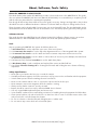
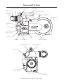
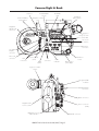
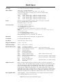
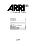
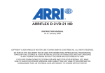
ARRIFLEX 416 Quick Guide
About, Software, Tools, Safety
3
Camera Left & Front
4
Camera Right & Back
5
Quick Specs
6
Power On, Camera RUN, Inching, Camera Display
7
Loading the Magazine
8
Mounting the Magazine
10
Camera Display – Fps & Shutter Angle
11
Camera Display – Options
12
On-board Battery OBB-2
13
Integrated Video System
14
Accessories
16
Timecode Operation
18
ARRI Group Addresses
20
04/2007
This page is left blank intentionally.
ARRIFLEX 416 Quick Guide 04/2007, Page 2
About, Software, Tools, Safety
About the ARRIFLEX 416 Quick Guide
This Quick Guide (order number K5.40076.0) provides a short introduction to the ARRIFLEX 416. This guide
does not replace the ARRIFLEX 416 Instruction Manual (K5.66324.0). It is essential that you acquaint yourself
with the instruction manual before operating the equipment.
Even though all efforts have been made to ensure this guide’s accuracy, changes and upgrades to the products
described can result in different hardware or behaviour. Technical data are subject to change without notice.
These documents can be downloaded from www.arri.com in Acrobat pdf format. The Acrobat Reader can be
downloaded free from the Adobe web site at www.adobe.com. A PostScript printer gives best printing results.
Software Version
This guide describes the ARRIFLEX 416 with Software Packet 01G. Different software versions can result in
different behaviour. Authorized ARRI Service Centres can check and update equipment software.
Tools
Anyone operating the ARRIFLEX 416 system should have these tools:
1.
2.
3.
4.
A 416 Shutter Tool is used to adjust the open sector of the mirror shutter.
A 1.5 mm metric hex wrench is used to adjust the alignment and focus of the Integrated Video System.
A 3 mm metric hex wrench is used to attach and remove camera components and most accessories.
A 5 mm metric hex wrench is used to attach or remove the 3/8” Accessory Shoe Adapter, the LWS-5 and
the WHA-2 Rosette Bracket.
5. A 8-10mm (5/16”) flat head screwdriver is used to attach base plates.
6. A Hirschmann clamp is used to withdraw and replace fibre screens and the field lens.
7. A red plastic film track cleaning rod for cleaning the film track and holding the mirror shutter still during
adjustment.
Safety Specifications
•
•
•
•
•
•
•
•
•
•
Never place your hand in the lens port or inside the camera.
Assembly and initial operation should be carried out only by persons who are familiar with the equipment.
Switch camera power off before making electrical connections.
Never run the camera without a lens or a protective cap mounted in the lens port.
Never attempt to remove the magazine while the camera is running.
Always ensure that the camera is securely mounted.
Repairs should be carried out only by authorized ARRI Service Centres.
Use only original ARRI replacement parts and accessories!
In wet weather conditions the normal safety precautions for handling electrical equipment should be taken.
Clean optical surfaces only with a lens brush or a clean lens cloth. In case of solid dirt moisten a lens cloth
with pure alcohol or a brand name lens cleaner.
• Do not use solvents to clean the film path, Plexiglas parts or rubber seals.
• Do not remove any screws which are secured with paint.
ARRIFLEX 416 Quick Guide 04/2007, Page 3
Camera Left & Front
Eyepiece focus ring
Image rotation
knob
Flip-out tape hook
416 Standard
Camera Handle
Optional centre leg
Image rotation
unlock button
Timecode sensitivity
switch
Magazine feed
side door lock
Heated Eyepiece
outlet
—
Tape hook
DIMMER
+
NORM
PS/CCU
LOCK
MODE
SEL/∆
SET/ V
PHASE
RGB ARRIGLOW
brightness buttons
RUN
PHASE button
Display
RUN button
RUN Indicator
Image rotation knob
416 Shoulder
Magazine 120/400
Image rotation unlock
button
Tape hook
PL lens port
(Super 16 only)
Front 3/8 – 16
mounting point
ARRIFLEX 416 Quick Guide 04/2007, Page 4
Camera Right & Back
Antenna
RF CHANNEL
selector
RF READY
LED
Integrated
Video System
Magazine release
lever
On-board Battery
release button
Magazine
take-up side
door lock
Eyepiece
swing over lock
L
RDY
R
L
R
L
R
Motor control LEDs
LDD
Lens motor
direction switches
Lens Data
Display
connector
Timecode
connector
LCS
connectors
Power on/off
switch
RUN
button
IRIS
FOCUS
ON/OFF
LCS
LCS
ZOOM
RF CHAN
TCC
RUN
RS
CLM-2 motor
connectors
RS
RS
connectors
RUN
indicator
Attachment
rosette
Film transport
pitch adjust
Eyepiece rotation
friction
IVS ground fault
indicator
MINI MONITOR
connectors
BNC connectors
Magazine film
reserve counter
Power connector
(BAT)
REMOTE connector
status indicator
ARRIFLEX 416 Quick Guide 04/2007, Page 5
REMOTE connector
Quick Specs
Fps range:
1 to 75 fps, forward only, in 0.001 fps increments
Mirror Shutter:
180º to 45º, manually adjustable
Fixed settings at: 180º, 172.8º, 150º, 144º, 135º, 90º, 45º
Use the following angles for filming with non-electronic ballast HMI
or fluorescent lighting:
180º:
25 fps, 50 Hz supply, 1/50th second exposure time
172.8º: 24 fps, 50 Hz supply, 1/50th second exposure time
150º:
25 fps, 60 Hz supply, 1/60th second exposure time
144º:
24 fps, 60 Hz supply, 1/60th second exposure time
Power:
24 V DC, custom 105 Fischer connector, pin 1 is 0 V, pin 2 is positive,
pin 3 is on-board battery condition monitor
Acceptable range: 21 V to 35 V
Accessory Power:
1 x 24 V RS connector on 416
2 x 24 V RS connectors on 416 Plus
1 x 24 V REMOTE connector
RS & REMOTE connectors combined 2 A continuous, 4 A peak
Note: RS & REMOTE connectors are not regulated so their output voltage tracks the
camera supply voltage.
1 x 24 V Heated Eyecup connector
2 x 12 V MINI MONITOR connector on IVS
MINI MONITOR connectors combined 2 A continuous
Movement:
One pull-down film transport claw and one registration pin
Sound Level:
Less than 20 dB (A) @ 24 fps
Lens Mount:
54 mm PL mount, Super 16 only
Flange Focal Distance:
51.98 – 51.97 mm
Temperature Range:
-20ºC to +50ºC (+4ºF to +122ºF)
Electronic Accessories:
OBB-2
LDD-FP
UMC-3
EXD-1
RCU-1
LCS
WRS
WRC-1
ESU-1
ICU-1
RS-4
APB
WL-2
416 On-board Battery
Lens Data Display for Focus Puller
Universal Motor Controller
External Display
Remote Control Unit
Lens Control System
Wireless Remote System
Wireless Remote Control
External Synchronization Unit
Iris Control Unit
Remote On/Off Switch
Accessory Power Box
Work Light
(Lens Data Archive only)
(Only for 416, not needed for 416 Plus)
(Yellow washer software only)
(Accessory expansion cable needed)
(Accessory expansion cable needed)
(Separate battery or Y-cable needed)
Other Accessories:
MEE-1 235/416 Medium Eyepiece Extension, LEE-1 235/416 Long Eyepiece
Extension, SCH-2 416 Standard Camera Handle, LMS-2 416 Low Mode Set, LRB-2
416 Left Rod Bracket, LWS-5 416 Lightweight Support, BP 10 & 11 Split Bridge
Plates, 416 Steadicam Plate, S-4 Shoulder Set, 16SR 3 fibre screens, HE-3, 4 & 5
heated eyecups, ARRI On-board Monitors, FF-3 (with bridge plate), FF-4 & 5 (on
lightweight support rods or bridge plate), 15 mm & 19 mm support rod matte boxes
(with bridge plate), ARRI/Zeiss Ultra 16 lenses, ARRI/Zeiss Lightweight Zoom LWZ-1,
ARRI/Zeiss Ultra Prime lenses, ARRI/Zeiss Master Prime lenses, Cooke S-4 lenses.
Not compatible with:
16SR magazines, 16SR on-board batteries, 435 Single Frame Hand Controller,
CCU and ARRICAM electronic accessories.
ARRIFLEX 416 Quick Guide 04/2007, Page 6
Power On, Camera RUN, Inching, Camera Display
Turning Camera Power On
The Power On button for the ARRIFLEX 416 is located above the RUN button on the camera right side. To turn
the camera On, briefly press the Power On button. When a battery is connected to the camera and the power
switch is turned on, you should see characters appear on the Display on the camera left side.
Note: The camera remembers the status of the Power On button and restores this status after a power interruption.
PHASE button
Power On button
ON/OFF
LCS
Camera right
RUN button
LCS
ZOOM
RF CHAN
TCC
NORM
PS/CCU
LOCK
MODE
SEL/∆
SET/ V
PHASE
RUN
RS
RUN
RS
RUN indicator
Camera left
RUN button
Camera RUN
To run the camera, press any RUN button briefly. The RUN indicator light will glow red while the camera
comes up to speed, changing to green once the set frame rate is reached. The RUN indicator light will glow
steadily green while the camera runs at the set frame rate. To stop the camera, briefly press the RUN button
again. If the RUN indicator glows red while the camera is in Standby, the camera is not ready and pressing
the RUN button will have no effect.
Note: If the PHASE button has not been pushed after power on or after a new magazine has been attached, the
first time RUN is pressed the camera performs a 2 second loop check before running.
Inching
The ARRIFLEX 416 cannot be manually inched – it can only be inched by pressing the PHASE button while
the camera is in Standby. If the PHASE button is pressed briefly, the mirror shutter will open to allow for gate
checks. To move the mirror shutter back into viewing position, press the PHASE button again briefly.
Camera Display Overview
1.
Total film exposed (or take counter)
5.
Standard speed.
Timecode User Bits
6.
2.
Programmed speed.
3.
Loudspeaker sequence & volume
Button backlight brightness
Take counter (or total film exposed)
Supply voltage & (with OBB-2),
battery capacity/running time left.
4.
Timecode User Bits
7.
ARRIGLOW colour
Timecode hours & minutes
Timecode minutes & framerate
Display Indicators:
asy:
bat:
end:
fps flashes:
TC glows:
TC flashes
Asynchronous operation (camera is not running at set fps)
Low battery (OBB-2: 23 volts, other batteries: 20.6 volts)
Camera has run out of film
ESU is not receiving a valid signal
Timecode exposure is enabled and timecode is set
Timecode exposure is enabled but not recording properly
Viewfinder Indicators:
LED glows:
LED flashes
Asynchronous operation (camera is not running at set fps)
Low battery (OBB-2: 23 volts, other batteries: 20.6 volts)
ARRIFLEX 416 Quick Guide 04/2007, Page 7
Loading the 416 Magazine
Note: The 416 magazine has its feed and take-up chambers on opposite sides to the SR 1, 2 & 3 magazines.
Step 1: The Feed Side
Load the unexposed film into the feed side in absolute darkness (darkroom or changing tent).
• Open the feed side magazine door and latch back the footage counter roller arm.
• Remove the film from the film can.
• Remove the tape from the film head. Ensure that the tape is completely removed and secured out of the way.
• Place the film roll on the core holder so it unwinds in the direction shown in the picture below. Press it down fully.
Note: When placing film on the feed side core holder, do not push on the film itself as it could become conical.
Push on the film core instead.
• Hold the film roll still and turn the core holder until the core holder key clicks into the key slot of the film core.
Make sure the core holder cannot turn any further.
• Release the footage counter roller arm gently so the roller rests on the outer surface of the film roll. The sides
of the roller should overlap the film roll edges, as shown in the picture below.
• Push approximately 15 cm (6”) of film into the slit at the top of the angled transfer roller. Then thread the film
around the guide roller.
• Hold the film still where it enters the transfer roller and gently back-tension the film roll to remove any slack.
• Replace and lock the feed side magazine door, being careful not to trap any film in the process.
Transfer roller
Feed side core holder
Guide roller
Footage counter roller
Step 2: The Take-up Side
The following procedures may be carried out in the light.
• Flip the magazine over lengthways so the take-up door is uppermost and the top of the magazine is facing
you. The ‘ARRI’ on the door will be upside down.
• Open the take-up side magazine door and latch back the lay-on roller arm. Fit an empty film core to the
take-up core holder.
• The film head should be protruding from the transfer roller. Check that it is cut squarely through a perforation.
• Thread the film head around the forward guide roller as indicated inside the magazine. Without touching the
film core, push the film head into the upper sprocket roller until its teeth engage in the film perforations.
• Once the sprocket teeth have engaged in the film perforations, turn the film core until the film head emerges
from the magazine throat.
ARRIFLEX 416 Quick Guide 04/2007, Page 8
Loading the 416 Magazine
Loop length mark
Rear guide roller
Magazine throat
Lower sprocket roller
Upper sprocket roller
Lay-on roller
Front guide
roller
Transfer roller
• Set the loop length by pulling the film head away from you and align it with the loop mark on the bottom of
the magazine (see picture above). Adjust the loop length by turning the take-up film core.
• Now take your hand off the film core – there is enough inertia in the sprockets to maintain the loop length.
• Hold the film between thumb and middle finger of your left hand, while using your index finger to push the
film head into the lower magazine throat slot. The angle at which the film enters is not as critical as it is on
SR magazines.
• Keep pushing the film in with your index finger until you see the sprockets rotate. Now take hold of the film
core again and rotate it counter-clockwise. This will pull the film from the throat into the take-up chamber.
Rear guide roller
Lay-on roller
• Thread the film around the rear guide roller following the path indicated in the magazine.
• Insert the film head into the film core (see picture right) and manually wind the core holder
two or three turns until the film winds tightly onto the core.
Correct
• Unlatch the lay-on roller arm.
• Close and lock the take-up side door.
• If using timecode, set the sensitivity switch according to the table on page 19 of this guide.
The switch is located at the top left corner of the feed side door.
Incorrect
ARRIFLEX 416 Quick Guide 04/2007, Page 9
Checking the Loop & Mounting the Magazine
Manually Checking the Loop Length
• Hold the magazine with the throat pointing up and the take-up door facing you.
• Slide your finger gently down the film loop so all the slack is pushed to the bottom of the throat. The lower
end of the loop should fall within the white painted line.
White painted line
Loop length adjustment button
Adjusting the Loop Length
If the loop falls outside the limits of the white line, it can be adjusted as follows after opening the take-up door:
• If the loop is too short, unwind the take-up film core slightly to release tension on the lower sprocket roller.
Hold the upper sprocket roller still with one finger and simultaneously press the loop length adjustment
button in the lower sprocket roller while pulling the loop gently from the lower throat. Release the button and
keep pulling the loop until the button pops up and the sprocket roller locks.
• If the loop is too long, hold the upper sprocket roller still with one finger and simultaneously press the loop
length adjustment button in the lower sprocket roller while turning the take-up film core counterclockwise.
Release the button and keep turning the film core until the button pops up and the sprocket roller locks.
Mounting the Magazine
• Insert the magazine throat into the magazine aperture in the back of the camera body and slide the
magazine forward until it locks in place.
Note: If the Shoulder Pad is attached to the camera, you will need to push down on the Shoulder Pad before
inserting the magazine.
Magazine
Release Lever
Safety Catch (in
locked position)
• Flip the silver Safety Catch on the Magazine Release Lever forward to prevent accidental release of the
magazine.
• Inch the camera by briefly pressing the PHASE button.
Note: After a new magazine has been attached or after camera power has been turned on, you should always
push the PHASE button to perform a loop check (the display shows ‘loop’). This takes about 2 seconds and
will engage the pull-down claw, check loop size and centre the loop properly.
ARRIFLEX 416 Quick Guide 04/2007, Page 10
Camera Display - Fps & Shutter Angle
The NORM and PS/CCU buttons above the display select between preset Standard Speeds and user
adjustable Programmable Speeds. Standard Speeds of 23.976, 24, 25, 29.97 & 30 fps are possible, while
the Programmable Speed can be set anywhere from 1.000 - 75.000 fps.
Note: If LOCK shows in the display, the camera settings are locked. To unlock, briefly press the LOCK button.
Setting the Standard Speed (NORM)
NORM
PS/CCU
LOCK
MODE
SEL/∆
SET/ V
• Make sure the display is in mode 1 (black bar visible). If not, repeatedly
press MODE until it is. If PS/CCU shows in the display, press NORM.
• If the total exposed film is displayed, pressing SEL steps first through
the digits of the top line then the Standard Speeds below. If take length
is displayed, pressing SEL will cycle only through the Standard Speeds.
• While the desired speed is flashing, press SET to set the speed.
Display in mode 1.
Speed set at 24.000 fps
Setting a Programmable Speed (PS/CCU)
• Press PS/CCU to switch from NORM to PS/CCU.
• Press MODE once to switch the display from mode 1 to mode 2.
• Pressing SEL selects one digit after another. The selected digit flashes.
• Press SET to increment the value of the flashing digit by 1.
• Repeat the last 2 steps for all the digits that need to be changed.
Final confirmation of the set speed is not necessary.
Display in mode 2.
Speed set at 75.000 fps
Checking the Mirror Shutter Angle
• With the camera in Standby, press and hold PHASE. The
camera will inch at approximately 1 fps.
• After 2 seconds the top line of the display shows the open angle
of the mirror shutter, while the bottom line shows the supply
voltage. With an OBB-2 connected, the bottom line can
optionally show the remaining battery capacity (in percent)
or the remaining running time (in hours).
Display with PHASE button
pressed. Open mirror shutter
angle 172.8º and supply of
voltage 26.9.
Changing the Mirror Shutter Angle
Note: Before adjusting the mirror shutter, check that it is in the
viewing position then turn off the camera and remove the
battery or power cable! Accidentally running the camera
during adjustment would cause catastrophic damage!
Red plastic film track
cleaning rod
• Remove the lens or lens port cavity cap and hold the mirror
shutter still by engaging the tip of the red plastic film track
cleaning rod in the slot in the centre of the mirror shutter.
Do NOT use a regular metal screwdriver.
• Insert the 416 Shutter Tool into the adjustment hole below the
mirror centre.
• Turn the 416 Shutter Tool until the desired Mirror Shutter preset
angle is reached. Angle presets are: 180º, 172.8º, 150º, 144º,
135º, 90º & 45º. Turning counter-clockwise reduces the angle.
416 Shutter Tool
ARRIFLEX 416 Quick Guide 04/2007, Page 11
Camera Display - Options
Setting the Total Exposed Film Counter
A new feature of the 416 is the option to enter a total exposed film quantity.
• Make sure the display is in mode 1 (black bar visible). If not, repeatedly
press MODE until it is. If PS/CCU shows in the display, press NORM.
• If the take counter is displayed in mode1 switch to total exposed film as follows:
– Press MODE twice to enter mode 3.
– Press SEL twice.
– Press SET once to switch the positions of the take and total exposed film counters.
– Repeatedly press MODE until mode 1 is displayed.
• Use the SEL button to select the digit you wish to change, which will flash.
• Use the SET button to change the value of the flashing digit. No confirmation is necessary.
Resetting the Total Exposed Film Counter
• Repeatedly press the MODE button until the total exposed film counter is
displayed (mode 1 or 3).
• Press and hold the SET button until the counter resets (approximately 3 seconds).
Beeper, Backlight & ARRIGLOW
The upper line of display mode 6 allows the user to decide whether and when the
beeper sounds and how loud (LS is shown for ‘loudspeaker’). The left-hand bar
shows the status of the start beep. The right-hand bar shows the status of the stop
beep. In each case, with the bar in the high position the beep will sound, in the
low position it will not. The final digit is the volume, which is adjustable between
0 (off) and 3.
The lower line of display mode 6 controls the brightness of the control buttons
backlight. This can be set between 0 (off) and 3.
The ARRIGLOW on the 416 gives the user a choice of frameglow colours.
Colours 1 – 8 are preset colours followed by U, which is user adjustable by
setting individual red, green and blue values. The ARRIGLOW brightness is
adjusted with the + and – buttons above the camera display.
Changing the Beeper and Backlight settings
• Use the SEL button to select the digit you wish to change, which will flash.
• Use the SET button to change the value of the flashing digit.
Changing the RGB ARRIGLOW colours
• Push the + DIMMER button on the camera left side so you can see the
ARRIGLOW in the viewfinder.
• Set the display to mode 7.
• Pushing the SEL button will make the ARRIGLOW number flash. Pushing the SET
button will now cycle through preset colours 1 – 8 and then user adjustable
colour “U”. Stop at the colour you like – no confirmation is necessary.
• To change the user adjustable colour, push SEL again while U is flashing. The
SEL button will now cycle through the red (r), green (G) and blue (b) values of
the user colour. Pushing the SET button changes the flashing colour value from
0 (no colour) up to 16 (maximum colour). No confirmation is necessary.
ARRIFLEX 416 Quick Guide 04/2007, Page 12
On-board Battery
On-Board Battery OBB-2
The OBB-2 On-Board Battery attaches directly to the camera body by means of a quick change mechanism
that can be easily operated with one hand. The OBB-2 incorporates a built-in power meter to indicate the state
of charge, while an extra contact in the power connector communicates this information to the camera. When
an OBB-2 is connected, display mode 3 can additionally show battery capacity (in percent) or remaining
camera running time (in hours). The remaining running time is calculated from the load on the camera since it
was powered-up and assumes the loading from accessories will not change.
Note: The new 416 power connector on the camera remains compatible with standard ARRI 24 volt power cables.
Mounting the OBB-2
• Fit the power plug of the OBB-2 into the camera power connector and slide the battery forward.
Removing the OBB-2
• Hold the OBB-2 as shown in the picture below and press the on-board battery release button.
• Pull the battery backwards until the power connectors disengage.
Battery power meter
On-board Battery
ARRIFLEX 416 Quick Guide 04/2007, Page 13
On-board Battery
release button
Integrated Video System
Flicker free
on/off button
White balance
button
Manual Gain
Control button
ENTER/INSERT
button
UP button
RIGHT button
LEFT button
MINI
MONITOR
connectors
DOWN button
Left/right
adjustment
Image rotation
M/ON/OFF
switch
Video out with
data or Y–signal
Clean Video out (no
data) or C–signal
Up/down
adjustment
Video lens IRIS
Focus
adjustment
M/ON/OFF switch
Make sure that the camera power is ON. Move the M/ON/OFF switch to ON (centre position).
To display a summary of all menu choices while the on-screen menu is not visible, press the M/ON/OFF switch
all the way to the left (it will spring back to the centre position when released).
To temporarily hide the on-screen menu while it is visible, press the M/ON/OFF switch all the way to the left.
This is useful to check the image while making adjustments in the on-screen menu.
White balance
Press the WB button to cycle through the five white balance settings. Four of these, AUTO (AWB), INDOOR
(IND), OUTDOOR (OTD) and MANUAL (MAN) have dedicated LEDs. The fifth setting, ONE PUSH WHITE, is
available when the ENTER/INSERT LED flashes.
AUTO
automatic white balance.
INDOOR 3200 K
when the illumination is tungsten and no colour correction filter is used.
OUTDOOR 5600 K
when the illumination is daylight or HMI and no colour correction filter is used.
MANUAL
manual white balance as controlled by the UP (increase blue), DOWN (decrease
blue), RIGHT (increase red) & LEFT (decrease red) buttons.
ONE PUSH WHITE
user adjustable – hold a white card in front of the lens and press ENTER/INSERT.
Controlling image brightness
Open the video lens IRIS fully and use either Automatic Gain Control or Manual Gain Control to control the
image brightness. Only close the video lens IRIS if the brightness exceeds the electronic control range.
ARRIFLEX 416 Quick Guide 04/2007, Page 14
Integrated Video System
Gain Control
• Press the MGC button to toggle between Manual Gain Control (LED on) and Automatic Gain Control (LED off).
• When MGC is off, Automatic Gain Control will adjust the image brightness.
• When MGC is on, adjust the image gain with the UP (increase gain) & DOWN (decrease gain) buttons.
The on-screen menu
The on-screen menu allows the adjustment or selection of the following features: Load & store settings, White
Balance, Gain, Colour Bars, video settings, Format Markings, Image Compare/Store, Text Inserter (camera
status, system status, user text, timecode & more) & VITC/WHITELINE.
• To display the main menu, press and hold the ENTER/INSERT button for 3 seconds.
• To select a sub-menu, use the UP & DOWN buttons. The arrow indicates which sub-menu is selected.
• To enter the selected sub-menu, press the RIGHT button.
• To go back to the main menu chose EXIT, which can be found at the bottom of each screen.
• To leave all menus, press and hold the ENTER/INSERT button for 3 seconds.
BNC mode
• Enter the VIDEO/TEXT ADJ sub-menu to chose between VBS (composite) and Y/C video signals to be output
by the video out (BNC) connectors under the BNC OUT option.
VBS
Left BNC:
Right BNC:
composite video with on-screen data.
composite video without on-screen data.
Y/C
Left BNC:
Right BNC:
Y (luminance) portion of the video signal.
C (chrominance) portion of the video signal.
How to get on-screen data in Y/C mode
• With Y/C selected in the VIDEO/TEXT ADJ sub-menu, the option of Y/C DATA, can now be toggled
between ON or OFF. If ON is selected then the Y/C signal will have on-screen data.
How to get black & white video
• Set the BNC mode to Y/C.
• Connect the video cable to the left video out (BNC) connector only.
How to adjust electronic sharpness
The 416 IVS has an electronic sharpness control which can be adjusted to optimize the look of the video output.
• Press and hold the ENTER/INSERT button for 3 seconds to enter the on-screen menu.
• In the VIDEO/TEXT ADJ sub-menu, adjust the value assigned to SHARPNESS for the best looking picture.
• To leave the on-screen menu, press and hold the ENTER/INSERT button for 3 seconds.
How to generate colour bars
To assist in setting up attached video monitors, the 416 IVS has the option to generate colour bars.
• Press and hold the ENTER/INSERT button for 3 seconds to enter the on-screen menu.
• In the WB/GAIN/BARS sub-menu, set COLOR BARS to ON.
ARRIFLEX 416 Quick Guide 04/2007, Page 15
Accessories
Split Bridge Plates BP-10 & BP-11
The BP-10 & 11 facilitate the balancing of the 416 on the tripod and elevate it to the proper height for the
mounting of accessories. They separate into two pieces to allow a quick change between tripod and hand-held
operation. The BP-10 uses 19 mm support rods where the BP-11 uses 15 mm support rods. The bridge plates
consist of the Accessory Carrier, the Sled, the Base Plate and a pair of 240 mm long Support Rods. To release
the Accessory Carrier from the Sled, release the lock lever on the Accessory Carrier, press the safety lock on
the Sled and pull the Accessory Carrier back and up. There are two release positions: The first is for use with
Lightweight Support mounted accessories (e.g. FF-4 – lens stays on camera) and the second is to clear the PL
mount of a large lens when quick disengagement of the camera is desired. A second person should secure the
lens in that case.
• The Accessory Carrier attaches to the camera base and accepts the 416 Shoulder Pad and 416 Left Rod Bracket.
• Combined with the Sled, the Accessory Carrier works like a conventional bridge plate.
• The Accessory Carrier will also attach to the Wedge Plate so a 416 in hand-held configuration can be
securely snapped into a tripod head when not in use.
416 Camera Body
416 Shoulder Pad - attaches with quick release mechanism,
no tools are needed
Accessory
Carrier
Lock
lever
416 Left Rod Bracket - attaches with 2 screws, 3 mm hex wrench needed
Safety
lock
Lock
lever
Sled
Wedge Plate
Base Plate
Tripod Head
416 Left Rod Bracket
The 416 Left Rod Bracket attaches to the Accessory Carrier for the fitting of a single 19 mm rod for use with
the Lightweight Follow Focus or a lens motor. It also has an Accessory Rosette for use with a left hand grip.
ARRIFLEX 416 Quick Guide 04/2007, Page 16
Accessories
416 Low Mode Support Set (LMS-2)
Low Mode Support Handle
Fits in 3 positions facing
forwards or back to optimize
camera balance.
Low Mode Riser
Allows use of Steadicam plate
with the viewfinder fitted.
Low Mode Bracket
Use on its own for the lowest low
mode configuration - viewfinder
needs to be removed to clear
Steadicam plate.
416 Side Bracket (SBR-2)
416 Lightweight Support (LWS-5)
The Side Bracket can be attached to the 416 and
supports the MB-20 I & II matte boxes using either
19 or 15 mm rods. A 5 mm hex wrench is needed
to fix the two mounting screws.
A sturdy bracket for 15 mm lightweight support rods
that attaches to the 416 by three screws - a 5 mm
hex wrench is needed.
Screw 1
Screw 1
Screw 3
Screw 2
Screw 2
416 Steadicam Plate
Because the LWS-5 projects below the line of the camera base a riser plate needs to be added when the 416
is top mounted on a Steadicam. The 416 Steadicam Plate adds the necessary distance and offers numerous
3/8 - 16 mounting holes.
ARRIFLEX 416 Quick Guide 04/2007, Page 17
Timecode Operation
Note: To write SMTPE timecode to film, ARRIFLEX 416 magazines must have the 416 Timecode Module fitted.
Note: Timecode recording is only possible at the 5 Standard Speeds of 23.976, 24, 25, 29.97 & 30 fps.
Turning Timecode Recording On and Off.
• Press the MODE key until the display shows mode 4.
• Press and hold SET until the TC symbol appears (or disappears)
on the display.
• Alternatively, Timecode recording is automatically turned on when
the camera receives a valid Timecode signal (see Timecode Input).
Display in mode 4. TC is
on. Frame rate is 25 fps
Timecode Input (Jam Syncing)
• Connect the LTC signal from a Timecode generator (or motherclock) to the Timecode connector on the
camera’s right side.
• The last 2 digits on the display will show ‘EC’ (external code). When the Timecode is correctly transferred
they will change to ‘CC’ (correct code).
• After approximately 10 seconds the last 2 digits will change to the Timecode recording frame rate.
Note: If the motherclock used is an Ambient ClockIt and it is left connected for 10 minutes, the camera’s Timecode
clock will synchronize itself to the exact frequency of the motherclock leading to better accuracy and extended periods between jam syncing.
Userbit Input
• Userbits are automatically input with the Timecode, but they can
also be set by means of the camera display in mode 5.
• Use the SEL button to select the digit you wish to change, which will flash.
• The SET button changes the value of the flashing digit.
• Repeat the last two steps for all the digits that need to be changed.
Display in mode 5.
Showing Userbits
Note: Userbit values are hexadecimal so available characters are 0 – 9 and A – F.
Magazine Timecode Sensitivity Switch
To ensure proper timecode exposure on film, the intensity of the exposure LED in the 416 Timecode Module is
adjustable. Magazines have a Timecode Sensitivity Switch in the top left corner of the feed side door for this
purpose. Different film stocks require the TCS Switch to be set to different TCS numbers. The table on the next
page shows the settings required by current film stocks.
Timecode sensitivity
switch
—
DIMMER
+
NORM
PS/CCU
LOCK
MODE
SEL/∆
SET/ V
ARRIFLEX 416 Quick Guide 04/2007, Page 18
Timecode Sensitivity Table
16 mm Kodak Film Stocks
Kodak 7201
(Color Negative)
Kodak 7205
(Color Negative)
Kodak 7212
(Color Negative)
Kodak 7217
(Color Negative)
Kodak 7218
(Color Negative)
Kodak 7222
(B/W Negative)
Kodak 7229
(Color Negative)
Kodak 7231
(B/W Negative)
TCS
TCS
TCS
TCS
TCS
TCS
TCS
TCS
7
6
6
6
5
8
5
8
16 mm Fuji Film Stocks
Fuji
8622
(Color
Fuji
8632
(Color
Fuji
8652
(Color
Fuji
8653
(Color
Fuji
8662
(Color
Fuji
8663
(Color
Fuji
8672
(Color
Fuji
8673
(Color
Fuji
8682
(Color
Fuji
8683
(Color
Fuji
8692
(Color
ARRIFLEX 416 Quick Guide 04/2007, Page 19
Negative)
Negative)
Negative)
Negative)
Negative)
Negative)
Negative)
Negative)
Negative)
Negative)
Negative)
TCS
TCS
TCS
TCS
TCS
TCS
TCS
TCS
TCS
TCS
TCS
6
6
5
6
4
5
4
5
6
6
4
ARRI Group Addresses
Australia
ARRI Australia PTY Limited (Sales, Service & Rental)
Unit 6C, 5 Talavera Road, Macquarie Park, Sydney. NSW 2113, Australia
Voice phone: +61 (2) 9855 4300, FAX: +61 (2) 9855 4301
Email: [email protected]
Canada
ARRI Canada Limited (Sales & Service)
415 Horner Ave. Unit 11, Toronto, Ontario M8W 4W3, Canada
Voice phone: +1 (416) 255 3335, FAX: +1 (416) 255 3399
Email: [email protected]
Germany
Arnold & Richter Cine Technik (Sales & Service)
Türkenstraße 89, D-80799 Munich, Germany
Voice phone: +49 (0)89 3809-0, FAX: +49 (0)89 3809-1245
Email: [email protected]
ARRI Camera Rental (Film Equipment Rental)
Türkenstraße 89, D-80799 Munich, Germany
Voice phone: +49 (0)89 3809-1240, FAX: +49 (0)89 3809-1798
Email: [email protected]
Great Britain
ARRI GB Limited (Sales & Service)
2 Highbridge, Oxford Road, Uxbridge, Middlesex, UB8 1LX, England
Voice phone: +44 (0)1895 457 000, FAX: +44 (0)1895 457 001
Email: [email protected]
ARRI MEDIA (Film Equipment Rental)
3 Highbridge, Oxford Road, Uxbridge, Middlesex, UB8 1LX, England
Voice phone: +44 (0)1895 457 100, FAX: +44 (0)1895 457 101
Email: [email protected]
ARRI Lighting Rental (Lighting Rental)
4 Highbridge, Oxford Road, Uxbridge, Middlesex, UB8 1LX, England
Voice phone: +44 (0)1895 457 200, FAX: +44 (0)1895 457 201
Email: [email protected]
Italy
ARRI Italia S.r.l. (Head Office, Milan)
Viale Edison 318, 20099 Sesto San Giovanni (Milan), Italy
Voice phone: +39 (02) 262 271 75, FAX: +39 (02) 242 1692
Email: [email protected]
ARRI Italia S.r.l. (Sales & Service, Rome)
Via Placanica 95, 00040 Morena (Rome), Italy
Voice phone: +39 (06) 726 707 97, FAX: +39 (06) 723 1541
E-mail: [email protected]
USA
ARRI Inc. (Sales & Service, East Coast)
617 Route 303, Blauvelt, NY 10913-1123, USA
Voice phone: +1 914 353 1400, FAX: +1 914 425 1250
Email: [email protected]
ARRI Inc. (Sales & Service, West Coast)
600 North Victory Blvd., Burbank, CA 91502-1639, USA
Voice phone: +1 818 841 7070, FAX: +1 818 848 4028
Email: [email protected]
ARRI CSC (Film Equipment Rental, NY)
619 West 54th St, New York, NY 10019, USA
Voice phone: +1 212 757 0906, FAX: +1 212 713 0075
Email: [email protected]
Web site:
ARRI CSC (Film Equipment Rental, Florida)
2385 Stirling Road, Fort Lauderdale, FL 33312, USA
Voice phone: +1 954 322 4545, FAX: +1 954 322 4188
Email: [email protected]
www.arri.com
ARRIFLEX 416 Quick Guide 04/2007, Page 20