1
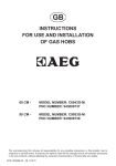
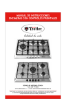
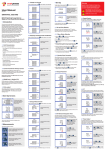
GUIDE D’INSTALLATION ET D’UTILISATION
FR - Table de cuisson
GUIDE FOR INSTALLATION AND USE
GB - Cooking Hob
MANUAL DE INSTALACIÓN Y UTILIZACIÓN
ES - Placa de cocción
GUIA DE INSTALAÇÃO E DE UTILIZAÇÃO
PT - Placa de cozinha
EINBAU- UND GEBRAUCHSANWEISUNG
DE - Kochfeld
GB
Dear valued customer,
To discover a De Dietrich product is to experience the range of unique emotions which
only high-value items can produce.
The attraction is immediate, from the moment you set eyes on the product. The sheer
quality of the design shines through thanks to the timeless style and outstanding finishes
which make each appliance an elegant and refined little masterpiece in its own right,
each in perfect harmony with the others.
Next, comes the irresistible urge to touch it. De Dietrich's design makes extensive use of
robust and prestigious materials. The accent is placed firmly upon authenticity.
By combining state-of-the-art technology with top quality materials, De Dietrich produces
beautifully crafted products to help you get the most from the culinary arts, a passion
shared by all lovers of cooking and fine food.
We hope that you enjoy using this new appliance and we would love to receive your
suggestions and to answer any questions you may have. Please feel free to contact our
customer service department via our website.
To benefit from the many advantages offered by the brand, we recommend that you
register your product at: www.de-dietrich.com.
Thank you for choosing a De Dietrich product.
De Dietrich
You can find a full range of information about the brand at www.de-dietrich.com
As part of our commitment to constantly improving our products, we reserve the right to make changes to
them based on advances to their technical, functional and/or esthetic properties.
IMPORTANT: before installing and using your appliance, please read this
Installation and Usage Guide carefully, as it will allow you to quickly familiarise
yourself with its operation.
1
TABLE OF CONTENTS
-- GENERAL NOTICEpag.3
-- INSTRUCTION FOR THE USERpag.4
Using the burnerspag.4
Electric plate usepag.4
Cleaningpag.5
-- INSTRUCTION FOR THE INSTALLERpag.6
Installing the toppag.6
Fastening the toppag.6
Installation roompag.6
Gas connectionpag.7
Electric connectionpag.7
Replacing the nozzlespag.7
Adjusting the burnerspag.7
Replacing the power supply cable
pag.8
-- MODELpag.9
-- TECHNICAL CHARACTERISTIC TABLESpag.10
-- AFTER SALES SERVICEpag.11
2
GENERAL NOTICE
It is very important that you keep this booklet together with the equipment for any future
consultation.
If this equipment should be sold or transferred to another person, make sure that the new
user receives the booklet, so that he can learn how to operate the appliance and read the
corresponding notice.
This is a Class 3 appliance.
This appliance complies with the following Directives:
EEC 2009/142/CE (Gas) 2006/95/CE (Low Voltage) EEC 2004/108/CE (Electromagnetic Compatibility)
EEC 89/109 (Contact with foods)
-- The installation must be carried out by experienced and qualified personnel, in conformity with the
regulations in force.
-- This appliance is not intended for use by person (including children) with reduced physical, sensory or
mental capabilities, or lack of experience and knowledge, unless they have been given supervision or
instruction cencerning use of the appliance by a person responsible for their safety.
-- Children should be supervised to ensure that they do not play with the appliance.
-- While the appliance is running, watch the children and make sure they neither stay near the equipment,
nor touch the surfaces that have not cooled down completely.
-- Before powering the equipment, check that it is properly adjusted for the type of gas at disposal (see the
“installation” paragraph).
-- Before carrying out the maintenance or cleaning the equipment, cut power supply off and make it cool
down.
-- Make sure that air circulates around the gas equipment. Insufficient ventilation produces a lack of oxygen.
-- In case of an intense or prolonged use of the equipment, it may be necessary to improve aeration, for
example by opening a window or increasing the mechanical suction power, if it exists.
-- The products of combustion must be discharged outside through a suction hood or an electric fan (see the
“installation” paragraph).
-- For any possible operation or modification, apply to an authorized Technical Assistance Centre and
demand original spare parts.
The product label, with the serial number, is sticked under the hob.
The manufacturer refuses all responsibility for possible damages to things or people, resulting
from a wrong installation or from an improper, incorrect or unreasonable use of this equipment.
3
INSTRUCTIONS FOR THE USER
It is necessary that all the operations regarding the installation, adjustment and
adaptation to the type of gas available are carried out by qualified personnel, in
conformity with the regulations in force.
The specific instructions are described in the booklet section intended for the
installer.
USING THE BURNERS
BURNERS
The symbols silk-screen printed on the side of the
knob indicate the correspondence between the
knob and the burner.
Automatic start-up with valves
Turn the corresponding knob anticlockwise up
to the maximum position (large flame, fig. 1) and
press the knob.
Power W
Ø of pots
Auxiliary
1000
10 - 14 cm
Semi-rapid
1750
16 - 18 cm
Rapid
3000
20 - 22 cm
Triple crown
3800
24 - 26 cm
Notice
-- When the equipment is not working, always check
that the knobs are in the closing position (see
fig.1).
-- If the flame should blow out accidentally, the safety
valve will automatically stop the gas supply, after a
few seconds. To restore operation, set the knob to
the lighting point (large flame, fig. 1) and press.
-- While cooking with fat or oil, pay the utmost
attention as these substances can catch fire when
overheated.
-- Do not use sprays near the appliance in operation.
-- Do not place unstable or deformed pots on the
burner, so as to prevent them from overturning or
overflowing.
-- Make sure that pot handles are placed properly.
-- When the burner is started up, check that the
flameis regular and, before taking pots away,
always lowerthe flame or put it out.
Once the burner has
been started up, keep
the knob pressed for
about 6 seconds.
Using the burners
In order to obtain
the maximum yield
Fig.1
without waste of gas,
it is important that the
diameter of the pot is suitable for the burner
potential (see the following table), so as to avoid
that the flame goes out of the pot bottom (fig. 2).
ELECTRIC PLATE USE
The electric-plate is operated with a seven position
switch and to turn the electric-plate on, rotate the
switch to any of the positions shown.
The red light is switched on when the electric-plate
is in operation.
Below as indicative basis, the settings to be used
for operating the electric-plate.
Warning
-- Use only flat pans and with sufficiently thick base,
equal or not much superior than that of the plate.
-- Do not switch the electric plate without the pan
over the plate.
-- Do not cook any food on the plate surface.
-- Turn off the plate few minutes before the cooking
end.
-- After use the electric plate remains very hot for
a prolonged period of time, do not tuch it and do
not place any object on top of the plate.
-- For a good preservation, the electric plate must
Fig.2
Use the maximum capacity to quickly make the
liquids reach the boiling temperature, and the
reduced capacity to heat food or maintain boiling.
All of the operating positions must be chosen
between the maximum and the minimum ones,
never between the minimum position and the
closing point.
The gas supply can be interrupted by turning the
knob clockwise up to the closing position.
If there is no power supply, it is possible to light the
burners with matches, setting the knob to the startup point (large flame, fig.1).
4
INSTRUCTIONS FOR THE USER
plate on its lowest setting (1) for about 30
minutes.
be thoroughly cleaned with appropriate cleaning
products which are readly available.
NB.: When operating for the first time, it is
necessary to eliminate any humidity or oil
which may accumulated around the electric
elements of the plate by operating the electric
KNOB
SETTING
HEAT
0
Off
1
Very low
2
Low
Heating medium quantities of liquid, to prepare sauces and
creams requiring long cooking.
3
Mild
To defrost frozen foods, cook stews, at to below boiling point.
4
Medium
For foods which require boiling point, delicate meat and fish.
5
Strong
6
Very strong
TYPE OF COOKING
To heat small quantities of liquids.
For roasting, grilling, stews.
To boil large quantities of liquid, to fry.
CLEANING
Burners and racks
These parts can be removed to make cleaning
easier.
The burners must be washed with a sponge and
soapy water or with a light detergent, wiped well
and placed in their housing perfectly.
Make sure that the flame-dividing ducts are not
clogged.
Check that the feeler of the safety valve and the
start-up electrode are always perfectly cleaned, so
as to ensure an optimum operation.
Before any operation, disconnect the appliance
from the electric grid. Don’t use a steam
cleaner for the cleaning the hob.
It is advisable to clean the appliance when it is
cold.
Enamelled parts
The enamelled parts must be washed with a
sponge and soapy water or with a light detergent.
Do not use abrasive or corrosive products.
Do not leave substances, such as lemon or tomato
juice, salt water, vinegar, coffee and milk on the
enamelled surfaces for a long time.
Gas taps
The possible lubrication of the taps must be carried
out by specialized personnel, exclusively.
In case of hardening or malfunctions in the gas
taps, apply to the Customer Service.
Stainless steel an alluminum parts
Stainless steel can be stained if it remains in
contact with highly calcareous water or aggressive
detergents for an extended period of time.
The stainless steel parts should also be cleaned
with soapy water and then dried with a soft cloth.
5
INSTRUCTIONS FOR THE INSTALLER
IMPORTANT NOTICE:
THE OPERATIONS INDICATED BELOW MUST BE FOLLOWED BY QUALIFIED
PERSONNEL EXCLUSIVELY, IN CONFORMITY WITH THE REGULATIONS IN FORCE.
THE MANUFACTURING FIRM REFUSES ALL RESPONSIBILITY FOR DAMAGES TO
PEOPLE, ANIMALS OR THINGS, RESULTING FROM THE FAILURE TO COMPLY WITH
SUCH PROVISIONS.
INSTALLATION
If the hob is going
to be installed on
the top of an oven,
precautions must be
taken to guarantee
an installation in
accordance with
current accident
p r e v e n t i o n
Fig.4
standards. Pay
particular attention to the position of the electric
cable and gas pipe: they must not touch any hot
parts of the oven.
Moreover, if the hob is going to be installed on
the top of a built in oven without forced cooling
ventilation, proper air vents must be installed to
guarantee an adequate ventilation, with the lower
air entering with a cross section of at least 200cm2,
and the higher air exiting with a cross section of at
least 60 cm2.
Installing the top
The appliance is designed to be embedded into
heat-resistant pieces of furniture.
The walls of the pieces of furniture must resist a
temperature of 75°C besides the room one.
The gas hobs are equipped with type X degree
protection against overheating. Therefore,
the appliance can be installed next to cabinets,
provided the height of the cabinet doses not
exceed that of the hob.
The equipment must not be installed near
inflammable materials, such as curtains, cloths,
etc.
Make a hole in the top of the piece of furniture, with
the dimensions indicated in fig. 3, at a distance of
at least 50 mm from
the appliance border
to the adjacent
walls.
Fastening the top
Every cook-top is equipped with a special washer.
A set of hooks is also supplied for mounting the
cook-top.
For the installation proceed as follows:
-- Remove the racks and burners from the top.
-- Turn the appliance upside down and lay the
washer S along the external border (fig. 5).
Fig.3
MODEL
L (mm)
P (mm)
DTE1114X / W / B
DTE1115X / W / B
DTE1172X / W
DTG1164X
DTG1175X / W
560
480
DTE1192X
DTG1195X
860
480
Fig.5
Fig.6
-- Introduce and place the cook-top in the hole made
in the piece of furniture, then block it with the V
screws of the fastening hooks G (fig.6.
Any possible wall unit over the cook-top must be
placed at a distance of at least 760 mm from the
top.
It is advisable to isolate the appliance from the
piece of furniture below with a separator, leaving a
depression space of at least 10 mm (fig. 4).
Installation room
This appliance is not provided with a device for
exhausting the products of combustion. Regarding
6
INSTRUCTIONS FOR THE INSTALLER
provided with an effective ground connction in
compliance with the regulations and provisions of
the law. Grounding is compulsory.
If the appliance is not equipped with a plug, apply
a standardized plug to the power supply cable.
This device must be at a suitable opening distance
from the contacts in order to allow the entire
disconnection in case of overvoltage category III,
in accordance with installation rules.
room ventilation rules where appliance is installed
make reference to the legislation, in conformity
with the local regulations.
FOR THE U.K. ONLY
The room containing this hotplate should have an
air supply in accordance with BS 5440: Part 2:
1989.
-- All rooms require an openable window, or
equivalent and some rooms will require a
permanent vent a well.
-- For room volumes up to 5 m3 an air vent of 100cm2
is required.
-- For room volumes between 5 m3 and 10 m3 an air
vent of 50 cm2 is required.
-- If the room is greater than 5 m3 and has a door that
opens directly to the outside, then no air vent is
required.
GAS TRANSFORMATIONS AND ADJUSTMENTS
Replacing the nozzles
If the equipment is adjusted for a type of gas that is
different from the one available, it is necessary to
replace the burner nozzles.
The choice of the nozzles to replace must be
made according to the table of the “technical
characteristics” as enclosed.
Act as follows:
-Remove the racks
and burners.
-By means of
a straight spanner L,
unscrew the nozzle U
(fig.8) and substitute it with
the corresponding one.
-Tighten the nozzle
Fig.8
strongly.
If there are other fuel burning appliances in the
same room BS 5440: Part 2:1989 should be
consulted to determine the air vent requirements.
Gas connection
Make sure that the appliance is adjusted for
the gas type available (see the label under the
appliance). Follow the instructions indicated in
the chapter “gas
transformations
and adjustments”
for the possible
adaptation to
different gases.
The appliance
m u s t
b e
Fig.7
connected to the gas system by means of stiff metal
pipes or flexible steel pipes having continuous
walls, in compliance with the regulations in force.
Some models are equipped with both cylindrical A
and conical B connectors for gas supply (fig. 7).
Please select the type which is correct for the
supply concerned.
The connection must not stress the gas ramp.
Once the installation is over, check the
connection seal with a soapy solution.
Adjusting the burners
The lowest flame point must always be properly
adjusted and the flame must remain on even if
there is an abrupt shift from the maximum to the
minimum position.
If this is not so, it is necessary to adjust the lowest
flame point as follows:
-- start the burner up;
-- turn the tap up to the minimum position (small
flame);
-- remove the knob from the tap rod;
-- introduce a flat-tip screwdriver C in the hole of
control panel of the tap (fig. 9) and turn the bypass screw V (fig.9/A) up to a proper adjustment
of the lowest flame point.
V
Electric connection
The connection to the electric grid must be carried
out by qualified personnel and in conformity with
the regulations in force.
The voltage of the electric system must correspond
to the value indicated in the label under the
appliance. Make sure that the electric system is
Fig.9
Fig.9/A
As regards G30 gas burners, the by-pass screw
must be tightened completely.
7
INSTRUCTIONS FOR THE INSTALLER
MAINTENANCE
type HO5VV-F or H05RR-F, complying with the
regulations in force.
The connection to the terminal board must be
effected as shown in fig.10:
Replacing the power supply cable
If the power supply cable should be replaced,
it is necessary
to use a cable
with a section
of 3x0.75mm2
for the version
all gas and 3x1
mm2 for the
version mixed,
Fig.10
brown cable L blue cable N green-yellow cable
8
(phase)
(neutral)
(ground)
modEl
DTG1164X
DTG1175X / W
DTG1195X
2
2
1
1
4
4
3
3
8
2
8
2
DTE1114X / W / B
DTE1115X / W / B
2
1
2
5
4
3
4
3
8
8
DTE1172X / W
DTE1192X
2
2
1
1
4
4
3
2
1 Rapid burner 2 Semi-rapid burner 3 Auxiliary burner 4 Triple ring burner 5 Electric plate
8 Control knob for burner
3
8
2
3000 W
1750 W
1000 W
3800 W
1500 W
9
8
TECHNICAL CHARACTERISTIC TABLES
BURNERS
N°
DESCRIPTION
1
RAPID
2
SEMI-RAPID
3
AUXILIARY
4
TRIPLE
CROWN
GAS
NORMAL
PRESSURE
NOMINAL
RATE
L/h
INJECTOR
DIAMETER
TAPE BY
PASS
DIAMETER
NOMINAL
HEAT INPUT
(W)
1/100 mm
1/100 mm
Max.
Min.
mbar
g/h
G30 / G31
28 - 30 / 37
225
-
85
42
3000
950
G20
20
-
290
115Y
Reg.
3000
950
G30 / G31
28 - 30 / 37
126
-
65
31
1750
600
G20
20
-
165
97Z
Reg.
1750
600
G30 / G31
28 - 30 / 37
71
-
50
27
1000
450
G20
20
-
99
72X
Reg.
1000
450
G30 / G31
28 - 30 / 37
278
-
98
60
3800
2100
G20
20
-
367
135K
Reg.
3800
2100
This product complies with EU Directive 2002/96/EC.
The crossed-out dustbin symbol reported on the appliance indicates that the appliance
must be disposed of separately from other domestic refuse at the end of its useful life.
It must therefore be delivered to a waste recycling centre specifically for electric and
electronic equipment or returned to the retailer at the moment of purchase of a new
equivalent appliance.
The user is responsible for delivering the appliance to the appropriate collection centre at the end of its
useful life, Failure to do so may result in a fine, as provided for by laws governing waste disposal.
Differential collection of waste products for eventual recycling, treatment and environmentally friendly
disposal helps reduce possible negative effects on the environment and health, and also enables the
materials making up the product to be recycled.
For more detailed information on the available refuse collection systems, refer to the local Municipal Solid
Waste disposal centre or the shop where the product was purchased.
Producers and importers are responsible for fulfilling their obligations as regards recycling, treatment and
environmentally friendly disposal by directly or indirectly participating in the collection system.
The manufacturing firm refuses all responsibility for any possible imprecision in this booklet, due
to misprints or clerical errors. It reserves the right to make all the changes that it will consider
necessary in its own products, without effecting the essential characteristics of functionality and
safety.
10