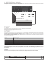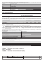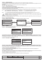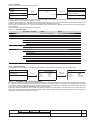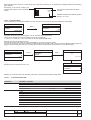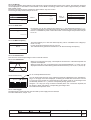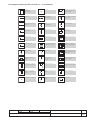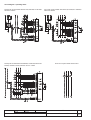
1
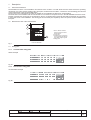
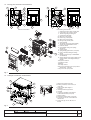
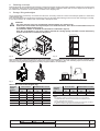
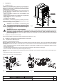
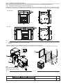
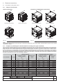
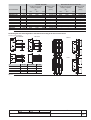
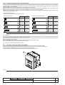
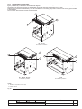
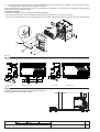
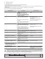
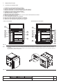
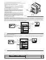
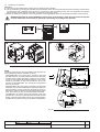
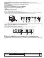
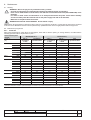
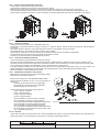
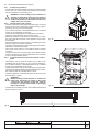
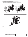
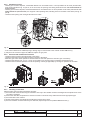
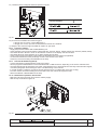
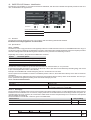
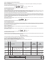
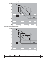
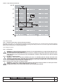
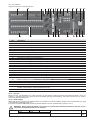
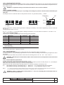
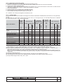
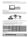
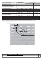
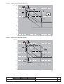
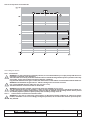
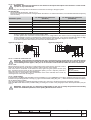
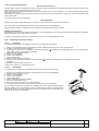
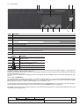
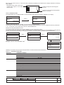
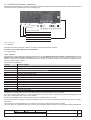
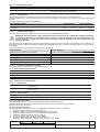
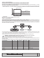
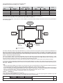
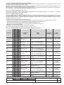
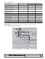
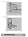
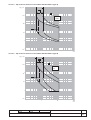
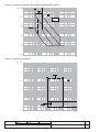
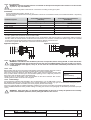
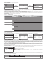
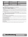
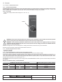
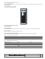
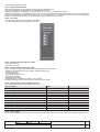
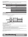
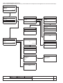
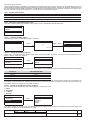
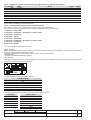
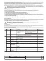
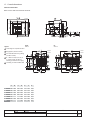
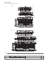
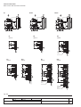
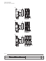
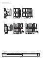
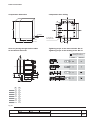
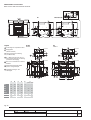
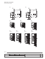
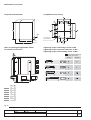
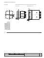
4.
Installation
4.1. Installation room
Install the circuit-breaker in a dry, dust-free, non-corrosive room,
and in such a way that it is not subject to shocks or vibrations.
Where this is not possible, install it inside a switchboard with a
suitable degree of protection.
For the preparation of the installation room, please refer to the
“Overall dimensions” paragraph, which gives information on
the following points:
- minimum installation volumes of the circuit-breakers and
derived versions
- distances to be respected for circuit-breakers in compartments
- overall dimensions of the circuit-breakers
- fixing drillings
- compartment door drillings.
The installation, commissioning and any ordinary and extraordinary maintenance have to be done by skilled personnel, with
a detailed knowledge of the apparatus.
WARNING: The installation, commissioning and
any ordinary and extraordinary maintenance of the
circuit-breaker and accessories must be performed
by skilled personnel, with a detailed knowledge of
the equipment.
Fig.8
WARNING ELECTRICAL SHOCK HAZARD:
Disconnect and lock and tag out all electrical power feeds to avoid any potential shock hazard when you are
assembling, installing maintaining or removing the circuit breaker from service. Some operations must be performed when the circuit-breaker is energized. In this case, reasonable care and compliance with all safe working
practices is required.
4.2. Installation of the fixed circuit-breaker
Fix the circuit-breaker to a horizontal surface using the screws (M10 x 12 min.).
4.3. Installation of the fixed part of the withdrawable circuit-breaker
4.3.1.
Preparation of the fixed part
Assembly of the anti-racking-in lock
Before installing the fixed part, it is necessary to check the presence of the anti-racking-in lock for circuit-breakers with different
electrical characteristics from those of the fixed part. If the anti-racking-in lock has been supplied separately, proceed to assemble
it as follows.
- On the self-adhesive plate (4), find the assembly position of the stop bolts in relation to the circuit-breaker which has to be
housed in the fixed part.
- Insert the hexagonal-head screws (1) in the holes found in the previous item as shown in the figure.
- Fix the screws with the washers (2) and the hexagonal stops (3).
Make sure that the anti-racking-in lock corresponding to the one installed on the fixed part is present on the circuit-breaker (moving part).
- Anti-racking-in plate on the moving part (5).
5
Example for E1B 08 according to the nameplate diagram
1
2
E3N-S
E2B-N-L
E1B-N
E3H-V
E2S-H
2
3
1
4
3
Fig. 10
Fig. 9
Model
L2234
L2778
L4681
L5179
L5439
Apparatus
Doc. no.
Emax
1SDH000460R0002
Scale
Page No
10/161