1
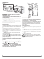
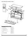
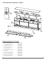
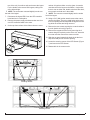
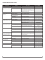
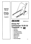
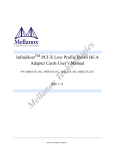
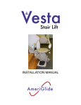
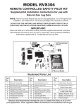
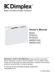
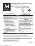
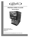
Service Manual
Model
VF2927L
VF5452L
UL Part Number
6909410210
6909410110
IMPORTANT SAFETY INFORMATION: Always read this manual first before attempting to service this fireplace. For your
safety, always comply with all warnings and safety instructions contained in this manual to prevent personal injury or property damage.
Dimplex North America Limited
1367 Industrial Road Cambridge ON Canada N1R 7G8
1-888-346-7539 www.dimplex.com
In keeping with our policy of continuous product development, we reserve the right to make changes without notice.
© 2014 Dimplex North America Limited
REV
PCN
DATE
00
-
25-SEP-14
7400850000R00
TABLE OF CONTENTS
OPERATION. . . . . . . . . . . . . . . . . . . . . . . . . . . . . . . . . . . . . . . . . . . . . . . . . . . . . . . . . . . . . . . . . . . . . 3
MAINTENANCE . . . . . . . . . . . . . . . . . . . . . . . . . . . . . . . . . . . . . . . . . . . . . . . . . . . . . . . . . . . . . . . . . . 4
EXPLODED PARTS DIAGRAM - SINGLE. . . . . . . . . . . . . . . . . . . . . . . . . . . . . . . . . . . . . . . . . . . . . . 5
EXPLODED PARTS DIAGRAM - DOUBLE. . . . . . . . . . . . . . . . . . . . . . . . . . . . . . . . . . . . . . . . . . . . . 6
WIRING DIAGRAM- SINGLE. . . . . . . . . . . . . . . . . . . . . . . . . . . . . . . . . . . . . . . . . . . . . . . . . . . . . . . . 7
WIRING DIAGRAM - DOUBLE. . . . . . . . . . . . . . . . . . . . . . . . . . . . . . . . . . . . . . . . . . . . . . . . . . . . . . . 7
FRONT GLASS REPLACEMENT . . . . . . . . . . . . . . . . . . . . . . . . . . . . . . . . . . . . . . . . . . . . . . . . . . . . 8
BOTTOM LOGSET REPLACEMENT. . . . . . . . . . . . . . . . . . . . . . . . . . . . . . . . . . . . . . . . . . . . . . . . . . 8
TOP LOGSET REPLACEMENT. . . . . . . . . . . . . . . . . . . . . . . . . . . . . . . . . . . . . . . . . . . . . . . . . . . . . . 8
LED CONTROLLER REPLACEMENT. . . . . . . . . . . . . . . . . . . . . . . . . . . . . . . . . . . . . . . . . . . . . . . . . 8
LED LIGHT ASSEMBLY REPLACEMENT. . . . . . . . . . . . . . . . . . . . . . . . . . . . . . . . . . . . . . . . . . . . . . 9
LED SCREEN REPLACEMENT . . . . . . . . . . . . . . . . . . . . . . . . . . . . . . . . . . . . . . . . . . . . . . . . . . . . . 9
TROUBLESHOOTING GUIDE. . . . . . . . . . . . . . . . . . . . . . . . . . . . . . . . . . . . . . . . . . . . . . . . . . . . . . 11
Always use a qualified technician or service agency to repair this fireplace.
! NOTE: Procedures and techniques that are considered important enough to emphasize.
CAUTION: Procedures and techniques which, if not carefully followed, will result in damage to the equipment.
WARNING: Procedures and techniques which, if not carefully followed, will expose the user to the risk of fire,
serious injury, or death.
2www.dimplex.com
OPERATION
Figure 2
Figure 1
A
B C
Volume
Controls
Battery
Cover
D
E F
IR Remote Sensor
WARNING: This electric firebox must be properly installed before it is used.
The power switch (Figure 2A) must first be switched “I” to
operate the appliance.
An ‘Opti-V’ logo will appear on the screen for about 3 seconds before the flame picture starts .
! NOTE: The user may notice a blank screen for approximately 5 seconds, every 30 minutes. This is normal
and should not be a cause for concern.
Manual Operation
The manual controls for the screen are located at the inner
top left hand side of the appliance above the glass.(Figure
2).
The mains (power) switch (Figure 2A) may be used to
switch the appliance Off (“O”) when it is not required, for
example, overnight or for long periods, to avoid unnecessary energy use.
! NOTE: Ensure that the mains (power) switch shall
remain readily operable.
The standby button “ ” (Figure 2B) is located just below
the power switch. A red light will indicate when the unit is in
standby mode. (Figure 2)
Standby
Button
Remote Control Operation
The remote control may be operated once the appliance is
switched to the ON “I” position (Figure 2A).
Aim the remote control at the IR remote sensor located on
the left of the fire display (Figure 2). The volume may be
adjusted up or down by pressing the volume control buttons ( + and -).
Battery Replacement
! NOTE: The remote control is packed separately in the
carton.
1. Slide battery cover open on the remote control (Figure
3).
2. Correctly install 2 1.5 Volt (AAA) battery in the battery
holder.
3. Close the battery cover.
Battery must be recycled or disposed of properly.
Check with your Local Authority or Retailer for recycling advice in your area.
The volume of the wood fire sound effects may be adjusted
up or down by pressing the volume control buttons (Figure
2C & 2D).
The screen brightness can be adjusted using the
2E) and
(Figure 2F) buttons. The
screen and the
(Figure
button darkens the
button brightens the screen. ! NOTE:On the VF5452L there are brightness controls
for each LED screen. The brightness controls for the right
screen are located in the center of the unit.
3
MAINTENANCE
WARNING: Disconnect power before attempting any
maintenance or cleaning to reduce the risk of fire, electric
shock or damage to persons.
Glass Cleaning
The glass is cleaned in the factory during the assembly
operation. During shipment, installation, handling, etc., the
front glass may collect dust particles, these can be removed by dusting lightly with a clean dry cloth.
To remove fingerprints or other marks, the glass can be
cleaned with a dry cloth. The glass should be completely
dried with a lint free cloth to prevent water spots. To
prevent scratching, do not use abrasive cleaners or spray
liquids on the glass surface.
Fireplace Surface Cleaning
To remove fingerprints or other marks, the exterior finish
can be cleaned with a damp cloth with a mild detergent.
The surface should be completely dried with a lint free cloth
to prevent water spots.
Servicing
Except for installation and cleaning described in this manual, an authorized service representative should perform any
other servicing.
4www.dimplex.com
EXPLODED PARTS DIAGRAM - SINGLE
9
5
3
1
6
2
8
7
Replacement Parts List - Single
1. LED Light Strip. . . . . . . . . . . . . . . . . . . . . . . . 9600880100RP
2. LED Light Controller. . . . . . . . . . . . . . . . . . . . 9600930100RP
3. Opti-V Remote Control . . . . . . . . . . . . . . . . . . 9600950100RP
4. Power Supply Wire Harness . . . . . . . . . . . . . 9600980100RP
5. Electrical Connector. . . . . . . . . . . . . . . . . . . . 9601030100RP
6. Single LED Screen Assembly. . . . . . . . . . . . . 9600890100RP
7. Glass . . . . . . . . . . . . . . . . . . . . . . . . . . . . . . . 9600910100RP
8. Lower Logset Assembly . . . . . . . . . . . . . . . . . 9600900100RP
9. Upper Logset Assembly . . . . . . . . . . . . . . . . . 9600940100RP
5
EXPLODED PARTS DIAGRAM - DOUBLE
3
5
11
1
10
6
2
4
2
7
9
8
Replacement Parts List - Double
1. LED Light Strip (2 per unit). . . . . . . . . . . . . . . 9600880100RP
2. LED Light Controller (2 per unit). . . . . . . . . . . 9600930100RP
3. Opti-V Remote Control . . . . . . . . . . . . . . . . . . 9600950100RP
4. Power Supply Wire Harness . . . . . . . . . . . . . 9600980100RP
5. Electrical Connector. . . . . . . . . . . . . . . . . . . . 9601030100RP
6. Double LED Screen Assembly. . . . . . . . . . . . 9600970100RP
7. Double Glass. . . . . . . . . . . . . . . . . . . . . . . . . 9601000100RP
8. Right Lower Logset Assembly . . . . . . . . . . . . 9600990100RP
9. Left Lower Logset Assembly . . . . . . . . . . . . . 9601010100RP
10. Right Upper Logset Assembly . . . . . . . . . . . . 9600960100RP
11. Left Upper Logset Assembly . . . . . . . . . . . . . 9601020100RP
6www.dimplex.com
WIRING DIAGRAM- SINGLE
LED Strip
LED Driver
L
N
E
Logbed - TOP LED
Mains
Supply
LED Screen Assembly
Logbed - BOTTOM LED
WIRING DIAGRAM - DOUBLE
LED Strip
LED Strip
LED Driver
LED Driver
Power Supply Wire Harness
LH Logbed
TOP LED
Mains
Supply
L
N
E
RH Logbed
TOP LED
Double LED Screen
LH Logbed
BOTTOM LED
RH Logbed
BOTTOM LED
7
FRONT GLASS REPLACEMENT
Figure 3
W
ARNING: Disconnect power before attempting any
maintenance or cleaning to reduce the risk of electric
shock or damage to persons.
Securing Screws
Tools required: Phillips head screwdriver
Suction Cups
1. Locate the glass retention strip at the top of the front
glass (Figure 3).
2. Remove the securing screws on either side of the
retention strip.
3. Apply the suction cups to the glass at a comfortable
distance to allow for easily removing the front glass.
4. Gently tilt the glass forward, lift up and lift the glass out
of the unit.
5. Reassembly in the revers order.
BOTTOM LOGSET REPLACEMENT
W
ARNING: Disconnect power before attempting any
maintenance or cleaning to reduce the risk of electric
shock or damage to persons.
retention strip.
3. Apply the suction cups to the glass at a comfortable
distance to allow for easily removing the front glass.
4. Gently tilt the glass forward, lift up and lift the glass out
of the unit.
Tools required: Phillips head screwdriver
Suction Cups
5. Remove the bottom logset (only the corresponding logset to the side that needs to be repaired on the double
unit). Locate the 4 screws that secure the logset to the
bottom of the unit (Figure 4) and remove the logset.
1. Locate the glass retention strip at the top of the front
glass (Figure 3).
! NOTE: The screws are recessed slightly into the ember bed of the logset.
2. Remove the securing screws on either side of the
retention strip.
6. On the top front surface of the firebox there are a second set of logs that reflect on to the glass. Locate the
nuts that secure the logset to the firebox - single units,
there is one on either end, double units there are three,
two on each end and one in the middle.
3. Apply the suction cups to the glass at a comfortable
distance to allow for easily removing the front glass.
4. Gently tilt the glass forward, lift up and lift the glass out
of the unit.
5. Locate the 4 screws that secure the logset to the bottom of the unit (Figure 4) and remove the logset(s).
! NOTE: The screws are recessed slightly into the ember bed of the logset.
6. Disconnect the logset LED’s from the LED controller
board.
7. Replace connection with new logset LED wire.
8. Reassembe in the revers order.
TOP LOGSET REPLACEMENT
W
ARNING: Disconnect power before attempting any
maintenance or cleaning to reduce the risk of electric
shock or damage to persons.
Tools required: Phillips head screwdriver
5/16” (8 mm) socket wrench
Suction Cups
1. Locate the glass retention strip at the top of the front
glass (Figure 3).
2. Remove the securing screws on either side of the
! NOTE: The nuts are recessed slightly into the ember
bed of the logset.
7. Using a 5/16” (M8) socket wrench remove the nuts to
remove the logset. There is a slight ledge at the top of
the front opening that will help hold the logset from falling while the screws are being removed.
8. The wiring for the logset is connected to the LED controller located on the botton panel of the firebox below
the bottom logset. Disconnect the LED connector for
the top logset from the LED controller and attach a
peice of string to the end that can be led through the
corner to pull the new LED connector back through.
9. Replace the top logset.
10. Reassemble in the reverse order.
LED CONTROLLER REPLACEMENT
W
ARNING: Disconnect power before attempting any
maintenance or cleaning to reduce the risk of electric
shock or damage to persons.
Tools required: Phillips head screwdriver
Suction Cups
8www.dimplex.com
Figure 4
remove the logset.
Approximate locations
of securing screws
(RH Double)
Approximate locations
of securing screws
(Single & LH Double)
1. Locate the glass retention strip at the top of the front
glass (Figure 3).
2. Remove the securing screws on either side of the
retention strip.
3. Apply the suction cups to the glass at a comfortable
distance to allow for easily removing the front glass.
4. Gently tilt the glass forward, lift up and lift the glass out
of the unit.
5. Single units - Locate the 4 screws that secure the logset to the bottom of the unit (Figure 4) and remove the
logset.
!
NOTE: The screws are recessed slightly into the ember bed of the logset.
Double units - Depending on which side is not working
correctly, remove the corresponding logset to access
the LED controller, i.e. the left logs and lights are not
working remove the bottom left logs.
6. Locate the LED controller and disconnect the wiring
connections noting their original locations.
7. Remove the LED controller and install the new one.
8. Reassemble in the reverse order.
LED LIGHT ASSEMBLY REPLACEMENT
W
ARNING: Disconnect power before attempting any
maintenance or cleaning to reduce the risk of electric
shock or damage to persons.
Tools required: Phillips head screwdriver
Suction Cups
! NOTE: The screws are recessed slightly into the ember bed of the logset.
Double units - Depending on which side is not working
correctly, remove the corresponding logset to access
the LED controller, i.e. the left logs and lights are not
working remove the bottom left logs.
6. The wiring for the light assembly is connected to the
LED controller located on the botton panel of the firebox below the bottom logset. Disconnect the LED connector for the light assembly from the LED controller
and attach a peice of string to the end that can be led
through the corner to pull the new LED light assembly
cord through.
7. Remove the light assembly by removing the two screws
located below the assembly and replace with new light
assembly.
8. Reassemble in the reverse order.
LED SCREEN REPLACEMENT
W
ARNING: Disconnect power before attempting any
maintenance or cleaning to reduce the risk of electric
shock or damage to persons.
Tools required: Phillips head screwdriver
5/16” (8 mm) socket wrench
Suction Cups
1. Locate the glass retention strip at the top of the front
glass (Figure 3).
2. Remove the securing screws on either side of the
retention strip.
3. Apply the suction cups to the glass at a comfortable
distance to allow for easily removing the front glass.
4. Gently tilt the glass forward, lift up and lift the glass out
of the unit.
5. Remove the electrical plug from the left hand side of
the unit ensuring that it cannot fall out of the back of the
unit (Figure 5)
6. Locate the 4 screws that secure the logset to the botFigure 5
1. Locate the glass retention strip at the top of the front
glass (Figure 3).
2. Remove the securing screws on either side of the
retention strip.
3. Apply the suction cups to the glass at a comfortable
distance to allow for easily removing the front glass.
4. Gently tilt the glass forward, lift up and lift the glass out
of the unit.
5. Single units - Locate the 4 screws that secure the
logset to the bottom of the unit (2 on either end) and
9
tom of the unit (2 on either end) and remove the logset.
For the double units remove both logsets, taking note
of the left and right.
! NOTE: The screws are recessed slightly into the ember bed of the logset.
7. Disconnect the logset LED’s from the LED controller
board and set in a safe place.
8. Remove the power supply wireharness that runs from
one LED controller board to the other.
9. On the top front surface of the firebox there are a secFigure 6
ond set of logs that reflect on to the glass. Locate the
nuts that secure the logset to the firebox - single units,
there is one on either end, double units there are three,
two on each end and one in the middle.
! NOTE: The nuts are recessed slightly into the ember
bed of the logset.
10. Using a 5/16” (M8) socket wrench remove the nuts to
remove the logset. There is a slight ledge at the top of
the front opening that will help hold the logset from falling while the screws are being removed.
11. Remove the two screws securing the center bracket to
the unit (double unit only) (Figure 6).
12. Remove the top panel of the unit by removing the 3
screws along the top back portion of the unit, start with
the outter two then remove the center one last.
13. Slide the top panel towards the back the let the front
drop down and pull out the front opening.
14. Locate the securing screws of the LED Screen (Figure
7) and remove the LED Screen.
15. Reassemble in the reverse order.
Figure 7
Securing Screws
Securing Screws
10www.dimplex.com
TROUBLESHOOTING GUIDE
PROBLEM
CAUSE
SOLUTION
PART NUMBER
General
Circuit breaker trips or fuse
blows when unit is turned
on
Short in unit wiring.
Trace wiring in unit.
Improper circuit current rating
Additional appliances may exceed the
current rating of the circuit breaker or fuse.
Plug unit into another outlet or install unit on
a dedicated 15 amp circuit.
Improper operation
Refer to Operation Section
No incoming power from the
electrical wall socket
Check fuse/breaker panel
Loose wiring
Check wiring connections
Defective LED screen
Replace LED screen
Fireplace does not turn on
using the Remote Control
Improper operation
Refer to Operation Section
Remote Control not working
Install new battery into the Remote Control.
Initialize Remote Control where necessary
Backlight on screen is On,
with sound but no picture
Loose wiring
Check wiring connections
SD Card not working
Switch the two SD Cards to ensure the
digital input has been saved correctly
Defective LED screen
Replace LED screen
Loose wiring
Check wiring connections
Defective LED screen
Replace LED screen
Appearance
Fireplace does not turn on
Manually
Replace Remote Control
Dark screen and no sound
Defective LED controller
Replace LED controller
Screen is blue with “No
memory card” displayed in
the top left hand corner
Loose SD Card
Ensure that the SD card is fully inserted
(located at the top of the unit, just above the
LED light assembly)
Logset is not lighting up
Loose wiring
Check wiring connections
Defective logset
Replace logset
Both top and bottom logset
are not lighting up
Loose wiring
Check wiring connections
Defective LED controller
Replace LED controller
Flame Frozen
Loose wiring
Check wiring connections
Defective LED screen
Replace LED screen
Improper operation
Refer to Operation Section
Defective LED screen
Replace LED screen
Single - 9600890100RP
Double - 9600970100RP
9600950100RP
Contact Customer
Service
Single - 9600890100RP
Double - 9600970100RP
Single - 9600890100RP
Double - 9600970100RP
9600930100RP
Refer to RP list for
specific part numbers
9600930100RP
Single - 9600890100RP
Double - 9600970100RP
Noise
No sound
Single - 9600890100RP
Double - 9600970100RP
11