1
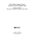
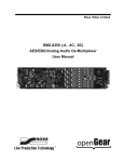
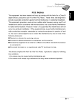
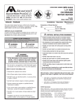
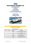
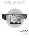
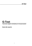
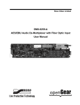
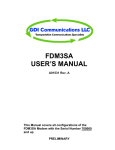
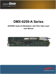
Preamplifier firmware version 2.2 Remote firmware version 2.0 Manual RevG remote microphone preamplifier owner’s manual all contents © Grace Design/ Lunatec LLC Welcome Thank you for purchasing the Grace Design m802 preamplifier system. With the combination of unmatched sonic performance, remote control capability and total reliability, the m802 is the ultimate, state of the art microphone preamplifier solution. We have designed the m802 to be as easy and intuitive to use as possible. However, we strongly recommend that you read this product manual thoroughly to familiarize yourself with the unique features and capabilities of the m802. Also, please do not hesitate to contact us directly if you have any questions, comments, or concerns with your new m802 microphone preamplifier system. Thanks for reading and happy recording!! -The Grace Design Team Table of Contents Welcome2 Important Safety Information 3 Overview4 Front Panel Diagram 5 m802 RCU Diagram 6 m802 Rearpanel Diagram 6 m802 Rearpanel with A/D Converter Diagram 7 m802 Power Supply Diagram 7 Installation8 Preamplifier Operation / Modes 11 A/D Converter Sensitivity Calibration 16 Operation within Pro Tools 18 Remote Control Unit Operation 19 Cable Diagrams 22 Specifications23 Cleaning and Maintenance 24 Warranty Information 25 Manual Revisions 26 2 Important Safety Information General • • • • • • • • • • • • • • Indoor use only Ordinary Protection: This equipment should not be exposed to dripping or splashing. Avoid placing objects filled with liquids, such as vases or glasses, on this equipment. Class I Equipment (grounded type) Electrical rating: 100-120/220-240V~ 50-60Hz 25W Mains supply voltage fluctuations are not to exceed ±10% of the nominal supply voltage. Pollution Degree 2 Installation (Overvoltage) Category II for transient overvoltages. Maximum Relative Humidity: <80% Operation temperature range: 10 °C to 40 °C Storage and transportation temperature range –40 °C to 70 °C Maximum altitude: 3000m (9843 ft) Equipment suitable for continuous operation Weight: preamplifier - 6.7kg (14.7lbs) / power supply unit - 2.8kg (6.25lbs) Safety Marking Symbols CAUTION: READ ACCOMPANYING DOCUMENTS This symbol, located on the equipment and in this manual, refers to important instructions. Read this manual thoroughly before operating this equipment. WARNING: ELECTRICAL SHOCK HAZARD This symbol, located on the equipment and in this manual, indicates the potential for electrical shock hazard. DC POWER OUTPUT This symbol, located on the equipment and in this manual, indicates a DC power output connection. Service Information The Grace Design m802 contains no user serviceable components. Contact Grace Design for repair and upgrade information. In the event that your Grace Design m802 needs to be returned to the factory, contact us for a return authorization number. 3 Overview System components The m802 system consists of an 8 channel preamplifier chassis, a power supply chassis, and an optional remote control unit (referred to as the RCU in the rest of this manual). The preamplifier chassis contains 8 audio amplifier PCBs, a micro controller PCB, and a front panel control interface. For remote control communications, the preamplifier chassis is equipped with two Philips I2C bus connectors (D-sub 9 pin) and MIDI IN and OUT connectors. The use of an external DC power supply unit ensures that no power line interference can compromise the performance of the sensitive microphone amplifier circuits. As well as the standard 48V phantom powered microphone inputs, the m802 can be ordered with optional 130V inputs for use with the DPA (formerly B&K) high voltage microphones. These microphones employ a high voltage transformerless impedance conversion circuit, which is not subject to the limitations of the 48V phantom powering standard. However, being unbalanced, the DPA 130V microphones benefit greatly from short cable runs from microphone to preamplifier. Additionally, an optional extremely high performance 8-channel analog-to-digital converter module is available for the m802. This converter module supports sample rates up to 192kHz at 24bit resolution. The RCU features an expanded version of the preamplifier front panel interface and has a single Philips I2C bus connector as well as a DC power Jack. Remote Control options The m802 preamplifier can be controlled by the RCU, via MIDI, or directly from its front panel. The RCU connects to the preamplifier via a Philips I2C serial buss, which makes parallel connections between all of the devices in the system. In an m802 system, the RCU is the master and all of the preamplifiers are slaves. The data on the display of the RCU is echoed back from the preamplifier so it shows the actual status of the preamplifier. For instance, when you tell a preamplifier to change its gain at the RCU, the RCU will send the gain change command to the preamplifier and then ask the preamplifier what its current gain setting is. The RCU will then update its own display to reflect the change. This gives the user absolute confidence that what is visible on the display is exactly what is happening at the preamplifier. If the RCU is disconnected from the preamplifier(s), the data fields in the display will go blank, but the preamplifiers will continue to operate normally. Please Note: The 9pin I2C is a proprietary interface. It is not compatible with RS-232, RS422, or any other 9 pin based serial protocol found in the recording studio environment. The RCU can control up to 8 preamplifiers (64 channels) by connecting it to one preamplifier and then connecting the remaining preamplifiers together with I2C cables in a daisy chain fashion. The RCU can be located up to 1000” (305 meters) away from the preamplifiers. Using the adapters included with the RCU, standard microphone cable can be used for this interface. Only one RCU can be connected to a system at any time. The m802 can also be controlled via MIDI. When the m802 sees any activity on its MIDI input port, it automatically switches into MIDI control mode. In this mode, the m802 will emulate a Digidesign® PRE 4 microphone preamplifier. After a period of 16 seconds with no activity on the MIDI input port, the m802 will automatically revert back to its normal control mode. See the MIDI Control section of this manual for more details on the MIDI control mode. Front Panel Diagram A D B ne +48V PEAK SETUP GROUP DATA (push) C G F E A +48 Volt phantom power pushbutton B Ø phase reverse pushbutton C GROUP pushbutton D PEAK indicator reset pushbutton E SETUP select pushbutton F DATA encoder with pushbutton G LCD display 64x240 pixels 5 m802 RCU Diagram remote microphone preamplifier J I H H CHANNEL SELECT 48V GROUP VIEW SETUP GAIN / EDIT push A C B D E F G A +48 Volt phantom power pushbutton F 7-segment LED display B Ø phase reverse pushbutton G DATA encoder with pushbutton C GROUP pushbutton H Page Up / Down pushbuttons D VIEW / peak indicator reset pushbutton I Channel Select pushbuttons E SETUP select pushbutton J LCD display 64x240 pixels m802 Rearpanel Diagram G F 6 A H E D B C C A MIC IN XLR Input E DC Power Input B DPA 130V input (optional) F MIDI Output C LINE OUT XLR output G MIDI Input D LINE OUT DB25 output H I2C REMOTE IN and OUT m802 Rearpanel with A/D Converter Diagram Digital Output Option A includes 2 sets of 8 channel AES3 outputs on DB25, Word Clock in and Out, and 1 set of AES3-id outputs on 4 BNC connectors. Digital Output option B inculdes 2 sets of 8 channel AES3 outputs on DB25, Word Clock in and Out, and 2 8 channel ADAT / Lightpipe outputs. m802 Power Supply Diagram A LED Voltage indicators B Power switch C AC line input front B A D DC output rear C D 7 Installation system connection diagram AC Line Input 100/120/220/230-240V~ GRACE DESIGN BOULDER, CO USA O I m802 Power Supply Unit DC Input 6.0-7.5VDC DC Power Cord +6.5,+18,-18,+48VDC m802 Preamplifier Unit push Remote Control Unit Audio Signal Inputs/Outputs I2C Interconnect Cord PREAMPLIFIER POWER CONNECTIONS An 8’ (2.8m) DC power cord is supplied to connect the power supply unit to the preamplifier unit. This cord can be identified by the 8 pin circular connectors at each end. Please note that the DC power cord should be connected before the AC power is turned on. This prevents incorrect power sequencing which can cause damage to the audio circuits. Warning: A damaged DC power cord can create a shock hazard as Voltages of 66VDC (148VDC with the DPA Input option) can be present. Do not operate the m802 with a damaged DC power cord. Replace a damaged DC power cord with a replacement from Grace Design (WA084) only. To avoid any interference with the low level audio circuitry, the power supply should be located at least 3’ (1m) from the preamplifier unit. POWER SUPPLY UNIT CONNECTIONS A standard AC power cable is included. For safety, the power supply cord must be connected to a grounded outlet. AC input voltage settings can be adjusted for 100V, 120V, 220V and 240V operation at 50-60Hz. If your voltage is 230V, use the 240V setting. From the rear of the power supply unit, open the trap door next to the IEC power inlet with a small screwdriver. Carefully pull the voltage select cam straight out and then insert with the desired voltage showing. Do not try to rotate the cam while it is in the power input module. Replace the fuses with the proper value selected from the fuse value table below (figure 1). Be sure to use a time delay type fuse with a 250V rating. 8 CAM SETTING 100V~ 120V~ 220V~ 240V~ 240V~ LINE VOLTAGE 100V~ 120V~ 220V~ 230V~ 240V~ FUSE VALUE 250V~ T 800mA L 250V~ T 800mA L 250V~ T 500mA L 250V~ T 500mA L 250V~T 500mA L figure 1 / fuse value table CHECK LINE VOLTAGE SETTINGS The power supply unit has been set from the factory to operate at the voltage required for your part of the world. However, it’s important to double-check this in order to ensure no damage will come to the unit if power is applied while the setting is incorrect. TURNING THE POWER ON The power switch is located on the front panel of the Power Supply Unit. Switching the rocker switch to the I position turns the mains power on. Switching the rocker switch to the O position turns the mains power off. REMOTE CONTROL UNIT POWER CONNECTION The RCU is powered with the supplied AC wall adapter. It is recommended that the I2C data connections be made before applying power to the RCU. Simply plugging the 2.1mm barrel connector into the DC power jack turns the power on. The m802 RCU is rated for 6.0-7.5V / 0.5A DC. (+) is in the center and (–) is on the outside sleeve. AUDIO CONNECTIONS Standard microphone input connections are made via female XLR connectors with pin 2 positive, pin 3 negative and pin 1 ground. 48V phantom power is supplied on pins 2 and 3. DPA® 130V microphone connections are made via the female 4 pin XLR connectors with audio on pin 4, 130V on pin 3 and ground on pin 1. On standard m802 preamp channels, two male XLR output connectors are available with pin 2 positive, pin 3 negative and pin 1 ground. (There is one male XLR output connector available on 130V DPA cards.) An additional set of parallel outputs is provided with a 25 pin D-sub connector (See the figure at the back of the manual – NOTE: this output is not available if the optional A/D converter module is installed). All output connectors can be used simultaneously. If the output is to be used unbalanced, pin 1 should be connected to signal ground and pin 2 to signal hot. Due to the nature of the balanced output stage, pin 3 should be left open for unbalanced operation (See CABLE DIAGRAMS p. 20). Note: This will provide a signal of positive absolute polarity when the preamplifier is being used with a microphone which produces a positive voltage on pin 2 with positive air pressure on the front of the diaphragm. While a vast majority of microphones conform to this standard a few do not. Use the phase reverse switch to compensate if necessary. Digital Audio Connections If the optional A/D converter module is installed, multiple digital outputs are available. The routing of the preamp outputs to the A/D converter is fixed. Each preamp channel feeds the corresponding con- 9 verter channel (1-8). The DB25 pin provides 8 stereo AES outputs, which can be configured for single or dual wire operation. In single wire operation AES outputs 1-4 are copied by AES outputs 5-8 providing two sets of (8-channel) digital outputs. In dual wire mode, AES outputs 1-4 carry audio channels 1-4 and AES outputs 5-8 carry audio channels 5-8. Please see the digital output table on page 20. The A/D converter module also has an additional set of outputs. These can be either 4 x AES3id BNC outputs or 2 x ADAT Lightpipe outputs – (the configuration is determined at time of purchase). The AES3id outputs each provide 2 channels of audio data in single wire mode or 1 channel of audio data in dual-wire mode. The ADAT lightpipe outputs provide 8 channels of audio data on each (at base rate). At dual rates the ADAT S-MUX is enabled and channels 1-4 are available on ADAT output 1, while channels 5-8 are transmitted on ADAT output 2. Quad sample rates are not supported over the ADAT interface. AES3id connector 1 2 3 4 ADAT connector Upper Lower AES3-id output connector configuration Audio channels 1-wire mode Audio channels 2-wire mode 1-2 1 3-4 2 5-6 3 7-8 4 ADAT output connector configuration Audio channels Fs = 44.1-48kHz Audio channels Fs = 88.2-96kHz (S-MUX) 1-8 1-4 1-8 5-8 figure 2 / digital output configuration Digital Clock Connections The m802 features an external clock input and clock output for syncronization to external clock sources. The clock input BNC connector can accept a WORDCLOCK signal running at the selected sample rate or a Digidesign Pro Tools® LOOPSYNC signal. For optimal performance when using the external clock connection, the m802 must be connected directly to a 75 Ohm clock source. The external clock input is terminated to 75 ohms within the m802 and thus should not be terminated elsewhere. The clock output connector signal can be derived from two different sources, either a buffered copy of the incoming clock signal on the wordclock input connector, or the internally generated WORDCLOCK. DATA CONNECTIONS m802 RCU Control: m802 RCU to Preamplifier data connections are made with an I2C serial cable. This cable has a male 9 pin D-sub connector at each end. The data cable can be up to 1000’ (304 Meters) in length. The I2C cable is connected to the 9 pin D-sub connector on the remote unit and to the I2C IN 9 pin D-sub connector on the preamplifier. As well, the RCU is supplied with a set of adapters that allow one to use a standard microphone cable for the serial data link. The microphone cable can be up to 1000’ long. It is not recommended to use a line in a multi-channel snake that contains mic level signals for this application, because the serial data activity can induce noise into adjacent low level audio signal lines. However, it is acceptable to include the data signal in a snake that contains only line level signals. Preamplifier-to-Preamplifier connections are made by connecting a 9 pin I2C cable from the I2C OUT connector on one preamplifier to the I2C IN connector on another preamplifier. Note: In a multiple preamplifier system, all preamplifiers must be powered on for the RCU to communi- 10 cate at all. If one preamplifier is accidentally powered down, the display on the RCU will go blank indicating that a preamplifier is not responding. This will not affect the continued operation of the remaining preamplifiers. If the un-powered preamplifier can not be powered on, then it must be disconnected from the data daisy chain to restore proper communication. If the I2C link between the RCU and the preamplifiers is interrupted by disconnecting the data cable, the RCU may freeze. If this happens, simply reset the RCU by removing its power momentarily. If the RCU does freeze, there is no effect on the continued functioning of the preamplifiers in the system. MIDI Control: The m802 MIDI IN connector can be connected to the MIDI output of a controller or a computer running Pro Tools®. Additional m802s can be connected in a daisy chain fashion by connecting the MIDI OUT from one preamplifier to MIDI IN on the next with the final preamplifier’s MIDI OUT connected to the MIDI IN on the Pro Tools® computer. Preamplifier Operation / Modes Channel select mode (A/D converter off) This is the default power on mode. In Channel Select mode the rotary encoder is used to select one of the eight visible channels on the LCD display for adjustment. When selected, the settings for a channel can be adjusted figure 3 / channel mode (A/D converter off) with the +48, PHASE, or DATA controls. Pushing the +48V or PHASE button toggles that function on or off for that channel. Pushing the DATA control enters the Gain Adjust mode. While in Gain Adjust mode, the gain numeric display characters at the top of the screen are highlighted and the rotary encoder adjusts the gain up or down in 1.5dB steps. Pushing the DATA control again exits the Gain Adjust mode and returns to the Channel Select mode. You will notice that changes can be made from the front panel of the preamplifier or at the RCU and both units will always show updated data. The bar graph meter at the right edge of each channel section is a 15 segment peak meter which indicates preamplifier output levels from –35dBu to +25dBu. Unlike the typical log scale level meter in a tape recorder, the m802 meter represents level in a mostly linear dB scale. This allows for a meter range of 60dB and useful peak output level information up to 4dB of the output clip point. When using the peak hold feature, you will notice that the peak hold indicator is a small line for all levels except +25dBu, which is indicated with a square “box”. The clipping level of the m802 is +25dBu. It should be noted that the bar graph meters in the m802 have an integration time that is approximately that of the DIN 45406 PPM meter standard. This means that it is possible to clip the preamplifier on transient program material without the meter indicating a full level. This is unlike the typical “over” indicator in a digital system which responds instantaneously to an overload. Note: You will notice that the meter ballistics will at first seem sluggish, but this arrangement actually provides more useful information about your peak levels and headroom status than a typical log scale meter. 11 Channel Select Mode (A/D converter On) When the optional A/D converter is installed and enabled, the m802 Channel Select Mode provides additional A/D converter related features and display information. Control of channel parameters (Gain, Mic Power and Phase Reverse) is achieved figure 4 / channel mode (A/D converter on) using the same method previously described. Once the A/D converter is enabled, the Channel Select screen on the m802 will show information regarding the current A/D converter configuration. Beginning at the bottom left and moving across to the right, the following information is displayed: Current sample rate, the A/D converter clocksource, professional / consumer data format, the AES3 transmission format, and the clock status. The clock status window can display the following status messages: Crystal: m802 ADC is running on the internal crystal oscillator. Locked: The first stage wide lock-range PLL is locked to the incoming clock signal but s-Lock has not been achieved. s-Lock: The s-Lock crystal based PLL has locked to the incoming clock signal. This assures the absolute highest rejection of incoming clock jitter. Invalid Clock: The message flashes to indicate that the first stage PLL is not able to lock to the incoming clock signal. This is usually indicates that the AdcFs setting does not match the incoming clock rate. The A/D converter also configures the m802 level meters to display a 0dBFS scale instead of the standard dBu scale. A/D converter sensitivity is factory set so that +22dBu level at the analog line outputs results in a 0dBFS level at the A/D converter. An A/D OVER indicator is also provided on each channel. Any OVER event will be latched until cleared by the user regardless of Peak Hold settings. SETUP MODE The Setup mode displays a series of menus for various user setup options. When the optional A/D con verter module is installed in the preamp there are a total of 6 setup menus and 4 if no A/D converter is installed. Step through the various setup screens on a preamplifier by pushing the SETUP button. Once in Setup mode, pressing the SETUP button will step the top line of the display through the following menus: Preset Store: * store preamp preset* #: 01 store: go The settings for each channel in a preamplifier can be manually stored for later recall in one of 15 user preset registers. Gain, +48V, Phase and Group settings as well as optional A/D converter settings are stored in the preset registers. To select a user preset register, first push the DATA control to highlight the preset number digits. Next turn the DATA control to increment the number to the desired register and then push the DATA control again. To store the preset, turn the DATA control until the word “Store:” is highlighted. Next, push the DATA control. This will highlight the word “go” as well. At this point turning the DATA control clockwise 12 or counter-clockwise will execute the store function. The display will briefly display “*** Confirmed ***” and then return to the Channel Mode. Note: A preamplifier will automatically store all of its current settings into a non-volatile memory whenever power is removed. When power is restored the preamplifier will retrieve these settings. This ensures that no settings are lost during power line interruptions. Preset Recall: *recall preamp preset* #: 01 store: go Registers 1 through 15 are available for user storage and recall. Register number 0 cannot be overwritten and contains a “null” set-up. The “null” setup sets all channels to the lowest gain setting, mic power off, phase reverse off, mic input to 48V and deletes any channel groups. Pre-set register 0 is helpful when setting up for a new session. Recalling a preset is identical to storing a preset (see Preset Store above). A/D converter and clock setup (Only available if A/D converter module is installed): Adcfs : AdcOFF Adc Clk : Int Clkout : CkIN The A/D converter / clock setup menu allows the user to configure the A/D converter sample rate and clock routing. Use the DATA knob to scroll to the parameter you wish to modify. Press and release the DATA knob to allow editing. Turning the DATA knob will then scroll through the available options for each parameter. Press and release the DATA knob once again to finish editing. The Adcfs field sets the rate at which the A/D converter will operate. In the “Off” position the A/D converter is disabled and all clocks are turned off. When using an external clock be sure that the sample rate setting matches the frequency of the incoming clock signal. The A/D converter Clocksource field determines which clock is used to derive the A/D sample clock. WORD and LOOP are the external clock sources and INTERNAL uses the on board crystal oscillator. The ClkOut field determines which clock is routed to the m802 clock output. CkIn routes a buffered copy of the incoming WORDCLOCK or LOOPSYNC clock to the clock output. Word routes the internally generated ultra-low jitter wordclock to the clock output. Digital Output Format: Digital format: cons Digital O/P : 1-wire The digital output format menu allows the user to configure the data output format to indicate professional (Prof ) or consumer (Cons) in the digital stream. The digital O/P field selects between single wire (1-wire) and dual wire (2-wire) operation. In single wire mode, the AES outputs function at the full sample rate and carry two channels of digital audio data. In dual wire mode, the outputs run at half the sample rate and carry one channel of digital audio data. Note that if 2-wire operation is selected here and the AD sample rate is set at 44.1 or 48kHz the m802 digital outputs will revert to 1-wire operation. The physical output configurations for each of these modes is discussed in the ”Digital Audio Connections” section 13 The Preamplifier ID: id: 1 peak : hld contrast : 126 backlight : on This field allows one to select a unique identification for each preamplifier in a system. The ID number also assigns channel numbers to the preamplifier. For instance, ID 1 includes channels 1-8, ID 2 includes channels 9-16 and so on to ID 8, which includes channels 57-64. Pushing the DATA knob once allows the ID number field to change by rotating the DATA knob. Pushing the DATA knob again saves the setting. When in MIDI control mode, the ID setting determines which MIDI channel the preamplifier is assigned to. Note: It is very important that all preamplifiers in a multiple preamplifier system have unique ID numbers. However, the ID numbers do not need to be contiguous. For example, you could have one preamplifier set to ID1 and another set to ID3. The result would be that in channel mode the RCU would page from channels 1-8 to channels 17-24. In meter mode (see page 18) you would see small dots over channels 1-8 and 17-24. Peak Hold: This field sets the behavior of the bar graph meters. Selecting “off” turns off the peak hold function. Selecting “dcy” sets the bar graph meters to hold the highest peak level for 3 seconds. Selecting “hld” stets the meters to hold the highest peak setting until the PEAK button is pressed. The Peak hold settings can be adjusted by pushing the DATA knob once and then turning the DATA knob until the desired function is visible. Pushing the DATA knob again saves the setting. Display contrast: The display contrast can be adjusted to optimize the display for various viewing angles. The Display contrast settings can be adjusted by pushing the DATA knob once and then turning the DATA knob until the desired contrast is achieved. Pushing the DATA knob again saves the setting. Back light control: The LCD display back light illumination can be turned off if desired. Input select: Rbbn 48v 48v 48v 48 v 48v 48v 48v The input select page of the setup menu is used to configure the input routing and configuration for each channel. The available options depend on the preamp’s hardware configuration. Turning the DATA knob selects a channel and pushing the DATA knob toggles the selected channel between the two input options. Note that when a channel’s setting is changed, the mic power on that channel will be turned off and must be turned on from the channel mode screen. For the standard microphone preamp channel, the available options are 48V and Rbbn (which denotes ribbon mic mode). Both of these modes use the 3 pin XLR microphone input and function identically except for the following features when ribbon mode is active: 1) The gain is increased by 10dB, effectively shifting the available gain range from -7.1dB – 63.0dB to 2.9dB – 73.0dB. This new gain is reflected on the user interface. “Rbbn” is also displayed on the corresponding channel’s status column. 2) +48V Phantom Power is disabled and locked-out. 3) The phantom power decoupling caps are bypassed, direct coupling the microphone to the preamp and minimizing components in the signal path. NOTE: This bypass function engages only after the decoupling caps have discharged to a low voltage level. Thus if phantom power was previously on, the bypassing will not be instantaneous. It should also be noted that no ribbon microphone should be connected until these caps have completely discharged. 14 If an optional 130V DPA preamplifier card is installed, the input selection will choose which physical connector is routed to the preamplifier. The options are: 48V (3 pin XLR) and 130V (4 pin XLR). Note: Ribbon mic mode is unavailable on any channel that has the 130V option installed. GROUP MODE The Group mode allows two to eight adjacent channels to be grouped together for gain change operations, which can be very convenient when using stereo pairs or groups of microphones on one instrument. To figure 5 / group mode enter group mode, push the GROUP pushbutton. The words “Group Mode Active” will appear just below the gain status characters. To define a group, place the cursor on the left most channel of the channels to be grouped and turn the DATA knob clockwise while pressing the GROUP pushbutton. You will notice that the vertical dividing lines between channels disappear as channels are added to a group (see figure 5 below). Once in Group mode, gain changes are made in the same manner as in normal Channel select mode. To remove a group, place the cursor on the right most channel of the channels in the group and turn the DATA knob counter clockwise while holding the GROUP pushbutton. You will notice that the vertical dividing lines between channels reappear as channels are removed from a group. Note: Groups are limited to adjacent channels only and groups cannot span between preamplifier units. Also, only gain can be adjusted when in Group mode. To toggle the status of Phantom power or Phase on a channel, you must exit Group mode. FRONT PANEL LOCKOUT MODE The front panel controls on an individual m802 can be locked to prevent unintended changes to its settings. Preamplifier settings can still be controlled from the RCU or via MIDI. To activate lockout mode, press and hold the DATA knob for 5 secfigure 6 / lockout mode onds. When in Lockout Mode, the words “interface locked” will appear on the LCD display (see figure 6 below). To exit lockout mode, press and hold the DATA knob for 5 seconds. The m802 will return to normal front panel control. Note that the m802 lockout mode can only be activated at the preamplifier front panel or via MIDI. Lockout mode cannot be activated from the RCU. MIDI Control Mode When the m802 detects activity on its MIDI input port, it will switch to MIDI Control mode. In this mode the m802 will emulate the Digidesign® pre microphone preamplifier. In Pro Tools® the mic pre controls 15 will control the m802 as if it were a Digidesign pre. If there is no activity on the MIDI input port for a period of 16 seconds, the m802 will revert to its normal control mode. Pro tools sends a “heartbeat” message to all preamplifiers that are declared in the pro tools setups > peripherals menu. The “heartbeat” signal happens every 8 seconds, which will keep the m802 in MIDI mode perpetually. If using a generic MIDI controller, the m802 will switch to MIDI Control mode whenever it sees a command on its MIDI input port and then switch back to normal control mode after 16 seconds of no MIDI activity. When in MIDI Control mode, the preamplifier can still be controlled at its front panel or from the m802 RCU. MIDI channel: for multiple m802 preamplifiers to exist on one MIDI buss, each preamplifier must be set to a unique ID number. The ID setting represents the MIDI channel by which the preamplifier will be controlled. An ID setting of 1 will cause the preamplifier to communicate on MIDI channel 0. An ID setting of 2 will cause the preamplifier to communicate on MIDI channel 1 and so on. The maximum number of m802 preamplifiers that can exist on a single MIDI buss is 8. Lockout: if the m802 receives a MIDI lockout command, the front panel controls will be locked out and changes can only be made via MIDI commands or from the RCU. To exit Lockout mode, send the MIDI unlock command or press and hold the data knob for 5 seconds. Group mode: m802 Group mode can be used when in MIDI control mode, but if a grouped channel’s gain is changed from within Pro Tools® (or by a MIDI controller) only that channel will change. Pro Tools® does, however, have its own preamp channel grouping functionality. A/D Converter Sensitivity Calibration The m802 A/D Converter (AT112 Rev B and higher) features two independent calibrations for input sensitivity. The software interface allows the user to easily switch between these two calibration settings. Each of the two sensitivity settings (A) and (B) can be configured for one of four standard sensitivities. The following sections detail the operation and calibration of this feature. Selecting the A/D Sensitivity In order to access the A/D Sensitivity Setup menu, the m802 must be powered down. Once off, press and hold the PEAK button and turn the preamp back on. After the system initializes, the ADC Sensitivity Setup menu will be displayed. This menu has two columns. The left column is used to select the current A/D sensitivity setting under the “ADC Sensitivity” menu item and the right column is used to select the actual sensitivities to be used in each setting. In addition to showing which configuration is selected (A) or (B), the calibrated sensitivity is shown in terms of both a maximum analog level as well as the corresponding digital headroom figure. To toggle between the two available sensitivity settings, click the encoder while “ADC Sensitivity” is highlighted. Rotate the encoder clockwise to select the (B) calibration or counter clockwise to select the (A) calibration. Once selected, click the encoder button again to exit the parameter edit mode. Turn the encoder until “DONE” is highlighted and click the encoder. The m802 will reboot and the A/D converter analog input section will reconfigure for the new sensitivity selection. Once set, the selected sensitivity is stored and remains active until it is changed by the user. Calibrating the A/D Sensitivity The m802 ships with the following two default sensitivity calibrations: 16 (A)+22dBu = 0dBFS (18dB Headroom) (B)+18dBu = 0dBFS (14dB Headroom) Internal trim controls allow you to reconfigure either (or both) of the sensitivity levels. Four standard sensitivities are supported in the m802 A/D converter. +18dBu = 0dBFS (14dB Headroom) +20dBu = 0dBFS (16dB Headroom) +22dBu = 0dBFS (18dB Headroom) +24dBu = 0dBFS (20dB Headroom) To recalibrate for a different A/D sensitivity do the following: The procedure in this section configures the m802 software: 1. 2. 3. 4. 5. 6. 7. 8. Power down the m802. Remove the 8 top cover screws using a #2 Phillips driver. Lift the top cover off the unit and set it aside. Enter the ADC Sensitivity Setup menu by powering up the m802 while the PEAK button is pressed. Move the encoder until “ADC Sensitivity” is highlighted. Click the encoder to edit the parameter. Rotate the encoder to choose the sensitivity setting you wish to modify ((A) or (B)). Click the encoder once the desired setting is selected. Now rotate the encoder to the right column until it highlights the Sensitivity CAL setting corresponding to setting ((A) or (B)) you just selected. Click the encoder and rotate it to choose between the four available sensitivities. Once selected, click the encoder again to disengage the parameter edit mode. Rotate the encoder until “DONE” is highlighted. Click the encoder and the preamp will reboot. Verify that the A/D converter is turned on. The procedure in this section configures the m802 hardware. The following steps should be repeated for each channel: Set the preamp gains to 16.4dB. Connect a signal generator to the channel input and connect a level meter that reads dBu to the output of the channel. 3. Increase the generator level until the level until the preamp output is +4dBu. 4. Using a non conductive tweaker tool, adjust the trim control corresponding to the current channel and sensitivity range (A) or (B). Each channel is labeled on the A/D converter analog input card (see figure 7 below). Trim (A) and trim (B) are also labeled. While adjusting the trim control, monitor the digital output on your recording device. Turn the trim until the digital level matches the desired headroom level. That is the level you will be adjusting to will be the desired headroom in decibels below full scale. For example if you have selected +20dBu = 0dBFS (16dB Headroom) for sensitivity (A), turn the trim (A) potentiometer until your digital meters read -16dBFS. If you have selected +24dBu = 0dBFS (20dB Headroom) for sensitivity (B), turn the trim (B) potentiometer until your digital meters read -20dBFS. 5. Once all channels have been recalibrated, shut down the m802 and reinstall the top cover. 1. 2. 17 figure 7 / A/D trim locations Operation within Pro Tools The m802 can be controlled directly from Digidesign ProTools® HD, via MIDI jacks on the m802 and the Digidesign I/O. Using the m802 with ProTools® requires some setup in ProTools® and the host computer’s MIDI configuration (MSS for windows, AMS for MAC). When connected to a ProTools® system, the m802 is designed to exactly emulate the Digidesign® Pre. This means that configuring the m802 in the “I/O” and “Peripherals” settings in ProTools®, it is necessary to choose the exact same settings as the Digidesgn®Pre. For a detailed discussion of Pro Tools® Pre configuration, please read the Digidesign® PRE user guide which can be found at the following URL: http://akmedia.digidesign.com/support/docs/PRE_ Guide_v80_56123.pdf (file subject to relocation). Chapter 3 includes operating system as well as Pro Tools® configuration information which will allow Pro Tools® to recognize the m802 as a Digidesign® Pre. Since the Digidesign® Pre and the m802 have differing features, there will be some m802 functions that are not available when in MIDI mode. As well, there are Digidesign® Pre functions that do not exist on the m802. Following is a summary of these limitations. Gain Control: the m802 has a gain range of -7 to 63.5Db in 1.5db steps. When in MIDI control mode the m802 switches to a gain range of 0 to 63db in 3db steps. If the m802 has channels set to gain values that are not available in MIDI control mode and the m802 receives MIDI activity, it will change these 18 channels to the next lowest gain setting that is available in MIDI control mode. If the MIDI control mode times out and the m802 returns to its normal control mode, all of the channel gain settings will be unchanged. The following table (figure 8) shows all of the gain settings available in the m802. The shaded cells indicate the gain settings that are available in MIDI control mode. -7.1dB -5.3 dB -3.8 dB -2.5 dB -1.0 dB 0.5 dB 2.0 dB 4.5 dB 6.0 dB 7.4 dB 9.0 dB 10.5 dB 12.0 dB 13.5 dB 15.0 dB 16.4 dB 17.9 dB 19.6 dB 21.0 dB 22.5 dB 24.0 dB 25.5 dB 26.9 dB 28.6 dB 30.0 dB 31.5 dB 33.0 dB 34.5 dB 36.0 dB 37.5 dB 39.0 dB 40.5 dB 42.2 dB 43.7 dB 45.0 dB 56.6 dB 48.0 dB 49.5 dB 51.0 dB 52.5 dB 54.0 dB 55.5 dB 57.0 dB 58.5 dB 60.0 dB 61.5 dB 63.0 dB figure 8 / gain settings Gain Control (in Ribbon mode): For any channel that is in ribbon mode, the MIDI gain control functions differently. If the m802 was made to follow the absolute Pro Tools® gain setting, the maximum available gain would only be +69dB, thus limiting the ribbon mode operation. In order to achieve the maximum m802 ribbon gain setting of +73.0dB, the actual gain of the m802 is 10dB higher than the reflected setting in Pro Tools®. For example, when in ribbon mode, a gain setting of +63dB in Pro Tools® equates to an m802 gain setting of +73.0dB or similarly a Pro Tools® setting of +60.0dB is actually +70.0dB on the m802. The same gain settings on the Pro Tools® interface (figure 8) are supported in ribbon mode. Pad: The m802 does not have a pad circuit so a PAD command will be ignored. Input Impedance: The m802 does not have adjustable input impedance so Input Impedance commands will be ignored. Mute: The m802 does not have a mute function so this command will be ignored. Input Select: The m802 does not have a line input, but we have mapped the line/mic MIDI command to select between the available inputs on each channel. On a standard preamp card, ribbon mode is activated if “LINE INPUT” is selected via MIDI. If an optional 130V DPA card is installed, the DPA 130V mic input is selected if “LINE INPUT” is selected via MIDI. Remote Control Unit Operation The m802 Remote Control Unit (RCU) features the same LCD display and DATA knob found on the front panel of the preamplifier. As well, most of the control conventions for the preamplifier apply when using the RCU. However, the RCU has additional pushbuttons for direct channel select, page up/down and view and a 3 digit numerical display which indicates the gain level of the currently selected channel. 48V: This button has the same function as the +48V button on the preamplifier unit, except that it lights up to indicate the microphone power status on the currently selected channel. Phase Reverse Ø : This button has the same function as the Ø button on the preamplifier unit except that it lights up to indicate the phase reverse status on the currently selected channel. 19 GROUP: The GROUP button has the same function as the GROUP button on the preamplifier unit except that it lights up to indicate that Group mode is active. Group mode functions the same way on the RCU as it does on the preamplifier unit. Note that the channel select buttons for all of the channels in a group will illuminate when their group is selected. To access Group mode from Meter mode, it is first necessary to return to Channel mode. CHANNEL SELECT: The channel select buttons allow direct access to a channel without having to turn the DATA knob. This can be handy when a channel is overloading and you need to access it immediately. The channel select button for the currently selected channel will illuminate green. Page Up/Down: The page Up button is labelled >> and the page Down button is labelled << . In a multiple preamplifier system, these buttons allow for immediate paging to the next preamplifier’s setup screen. Scrolling the cursor with the DATA knob will also allow for paging between preamplifiers. For example, in a 2 preamplifier system (16 channels), the RCU will show two pages: channels 1-8 and channels 9-16. With the cursor on channel 8, turning the DATA control one click clockwise will figure 9/ meter mode page the screen and move the selected channel to 9. View: Pressing the VIEW button momentarily clears the peak indicators on the bar graph displays. Pressing and releasing the VIEW button will also clear any digital over indicators. Pressing and holding the VIEW button enters and exits Meter mode. (See figure 8) Meter Mode: Pressing and holding the VIEW button for 1 second switches the LCD display into Meter mode. In Meter mode, the LCD displays bar graph level meters for up to 24 channels at a time. The DATA control is used to highlight an individual channel. The display will “page” from channels 1-24 to channels 25-48 and then to channels 49-64 as the page up or page down buttons are pressed or the DATA control is rotated. The Channel Select buttons will illuminate with the selected channel as well. Pushing the DATA knob or pressing the illuminated Channel Select button when a given channel is highlighted zooms to the Channel mode for channel parameter adjustment. In meter mode, there are always 64 channels of meters available to view even if there are only 8 channels (one preamplifier) in the system. There will be a small dot above the channel numbers where there is an actual preamplifier in the system. The picture below shows the meter mode for a system with 2 preamplifiers (16 channels). Pressing and holding the VIEW button for 1 second will return the LCD display to Channel mode. When the optional A/D converter is active on preamp in the system, it will be reflected on the Meter Mode screen. Underneath the corresponding channels “A/D On: dBFS Scale” will be displayed. This indicates that the scale is no longer in dBu, but rather dBFS just like Gain mode. Any digital overs that occur 20 in the A/D converter will be latched and displayed as small ovals above each meter. Note that when in Meter mode, the RCU will not indicate the status of mic power, phase rev or gain of the selected channel, because the RCU is using the full bandwidth of the I2C serial interface to transmit level data from multiple preamplifiers simultaneously. SETUP: On the RCU, setup mode is accessed by pushing the SETUP pushbutton. Setup mode on the RCU contains the same menus as Setup mode on the preamplifier, with a few important distinctions. A/D converter Setup: For any preamp with the optional A/D converter module installed, the m802 RCU gives the user access to all of the converter setup parameters (except clock output selection). These controls do not function in a global manner like the preset operations, but rather affect the preamp that is currently active. Thus each A/D converter in the system can have its own independent configuration. Like all other adjustable parameters, the remote control sends A/D converter setup commands and the preamp acts on it. This results in a slight latency when adjusting A/D converter parameters from the remote control as the configuration is completed before the status is confirmed on the RCU. Preset Store: Note that preset store menu displays *Store System Preset*. When you store a preset from the front panel of a preamplifier, you are storing settings in that preamplifier only. If you store a preset from the RCU, a store command will be sent to all of the preamplifiers in the system. On the RCU the menu will indicate: *Store System Preset* #: 01 Store : GO Preset Recall: Note that the preset recall menu displays *Recall System Preset*. When you recall a preset from the front panel of a preamplifier, you are recalling settings from that preamplifier only. If you recall a preset from the RCU, a recall command will be sent to all of the preamplifiers in the system. On the RCU, the recall menu will indicate: *Recall System Preset* #: 01 Store : GO It is important to understand that all of the presets are stored in the preamplifiers and not in the RCU. The RCU simply sends commands to the preamplifiers to store and recall presets. Setup Mode can not be entered from Meter Mode or Group mode. You must return to Channel mode before entering Setup mode. 21 Cable Diagrams I2C over CAT5 cable diagram Digital Output Configuration 1 6 2 7 3 8 4 9 5 1 6 2 7 3 8 4 9 5 GREEN WIRE IS CAT5E WHITE/GREEN R2 # Of Preamps 5 3 AES6 6 4 5 AES7 820 Ohms 1.1K Ohms 2.2K Ohms 4 8 1 2 7 6 R1 R2 value +/-5% 1 2 3 DB9 MALE 7 AES5 When using I2C interface cables over 500' (152 meters) with fewer than 4 preamplifiers, care must be taken to terminate the I2C bus at the preamplifier end to a resistance between 330 and 900 Ohms. Each preamplifier has a termination resistance of 2.49k Ohms. Build a terminator plug with resitors that will create a parallel resistance of 330-900 Ohms. Plug the shorting plug into the unused I2C connector on the last preamplifier. R1 3 6 AES4 Shorting Plug 2 4 5 AES3 DB9 MALE 1 3 AES2 DB9 MALE 1 6 2 7 3 8 4 9 5 CHANNEL # DUAL WIRE CHANNEL # SINGLE WIRE 1 AES1 2 BLUE WHITE/BLUE 7 8 AES8 8 Standard I2c Cable Diagram RED 1 6 2 7 3 8 4 9 5 1 6 2 7 3 8 4 9 5 BLACK DRAIN/SHIELD WIRE IS BELDEN 1883A 24 AWG TWISTED PAIR WITH FOIL SHIELD DB9 MALE DB9 MALE Serial Connector Pin Assignments m802 RCU DB9 pinout 5 4 3 9 1) 2) 3) 4) 5) 8 2 7 I2C DATA I2C CLOCK RS232 TX RS232 RX GND m802 Preamplifier DB9 pinout UPPER CONNECTOR 1 5 6 6) 7) 8) 9) 4 9 1) 2) 3) 4) 5) NC NC 7.5VDC IN NC 3 8 2 1 7 I2C DATA I2C CLOCK NC NC GND m802 Preamplifier DB9 pinout LOWER CONNECTOR 5 6 4 9 1) 2) 3) 4) 5) 6) NC 7) NC 8) NC 9) +5V 3 8 I 2C 2 7 1 6 6) NC 7) RS232 RX GND 8) NC 9) +5V DATA I2C CLOCK RS232 TX RS232 RX GND 25 Pin D-sub Output Connector AES-3 digital pinout Analog pinout (ch2) (ch1) G C H G C (ch3) H G C (ch4) H G C (ch5) H G C (ch6) H G C (ch7) H G C (ch8) (AES5) H G C H 2 1 13 H G C (AES7) H G C (AES8) H G C (AES1) H G C (AES2) H G C (AES3) H G C (AES4) H G C H 2 1 13 12 25 11 24 10 23 9 22 8 21 H = HOT 7 20 6 19 C = COLD 5 18 4 17 3 16 G = GROUND Unbalanced Output Cable Termination HOT 2 1 GND SHIELD 3 (OPEN) 22 G C (AES6) 15 14 12 25 11 24 10 23 9 22 8 21 H = HOT 7 20 6 19 C = COLD 5 18 4 17 G = GROUND 3 16 15 14 Specifications PREAMPLIFIER SPECIFICATIONS FREQUENCY RESPONSE @ 40.5dB gain ± 0.2dB 50Ω source 15Hz-300KHz @ 40.5dB gain ± 3dB 50Ω source 4.5Hz-1.0MHz THD+N @ 19.6dB gain +20dBu out, 1kHz <.0007% @ 40.5dB gain +20dBu out, 1kHz <.0010% @ 60.0dB gain +20dBu out, 1kHz <.0050% INTERMODULATION DISTORTION @40dB gain +20dBu out SMPTE/DIN 1:1 (50Hz, 7kHz) <.0015% SMPTE/DIN 4:1 (50Hz, 7kHz) <.0040% NOISE - REFERRED TO INPUT @60dB gain 50Ω source -129dB @60dB gain 150Ω source -127dB @60dB gain 600Ω source -123dB PHASE DEVIATION 100-20KHz @40.5dB gain <3° CROSSTALK Any Channel @40.5dB gain 1kHz -110dB CMRR @60dB gain, 3.5Vcm, 1KHz >70dB @60dB gain, 3.5Vcm, 10KHz >70dB PHANTOM POWER Voltage +48V +0.9/ -0.0 6.8kΩresistor match tolerance +/- 0.01% MAXIMUM OUTPUT LEVEL Balanced +27dBu Unbalanced +21dBu IMPEDANCE Input 4350Ω Output 200Ω DIMENSIONS 14.7lbs (6.7kg) Weight Height 2U Width 19” Depth 10” POWER SUPPLY SPECIFICATIONS POWER CONSUMPTION 100-240VAC 50/60Hz 60 Watts max DIMENSIONS Weight 6.25lbs (2.8kg) Height 1.7” Width 8.5” Depth 8.5” 23 A/D CONVERTER SPECIFICATIONS DYNAMIC RANGE 20Hz-20kHz “A” weighting >115dB >117dB THD+N 1kHz, -1dBFS, 20Hz-22kHz Frequency response 44.1kHz Fs 48kHz Fs 88.2kHz Fs 96kHz Fs 176.4kHz Fs 192kHz Fs +/-0.2dB 5Hz-21kHz 5Hz-23kHz 5Hz-41kHz 5Hz-45kHz 5Hz-54kHz 5Hz-59kHz Full scale input level +16dB or +24dB (+/-2dB trim) < 0.00026% (-112dB) -3dB 22kHz 24kHz 44kHz 48kHz 72.5kHz 79kHz CMRR 60Hz 1kHz 10kHz IMD SMPTE 4:1 60Hz, 7kHz, -3dBFS >65dB >80dB >60dB <100dB (0.0008%) Interchannel crosstalk <120dB GROUP DELAY 44.1-48kHz 13/Fs MAXIMUM NON-HARMONIC SPURIUS TONES 1kHz, -1dBFS, 20Hz-22kHz <-130dBFS Sample rates, internal crystal 44.1, 48, 88.2, 96, 176.4, 192(kHz) EXTERNAL CLOCK LOCK RANGE Wide lock mode s-Lock™ mode 40.1kHz-207kHz (+/-8% at each sample rate) +/-250ppm (+350, -400ppm typical) INTRINSIC JITTER, 200HZ-20kHz BW Wide lock mode s-Lock™ mode < 60ps RMS < 40ps RMS JITTER REJECTION CORNER FREQUENCY Wide lock mode, -3dB, 12dB/octave s-Lock™ mode, -3dB, 12dB/octave 800Hz 10Hz Cleaning and Maintenance Your m802 amplifier chassis is constructed out of high quality stainless steel. Under normal circumstances, virtually no maintenance is required to keep the unit looking shiny and new. However, if your unit becomes smudged or dirty, here are some cleaning tips: We recommend using either Pledge furniture polish or Zep brand stainless steel cleaner (available at the hardware store). Apply cleaner to a clean, dry, lint free cloth and gently wipe all stainless surfaces, taking care not to allow the cleaning product to build up around the panel switches or knobs. 24 Warranty Information • Grace Design warrants all of our products to be free of defective parts and workmanship for a period of five years. • This warranty period begins at the original date of purchase and is transferable to any person who may subsequently purchase the product during this time. • This warranty excludes the following conditions: normal wear and tear, misuse, customer negligence, accidental damage, unauthorized repair or modification, cosmetic damage and damage incurred during shipment. • During the time of this warranty, Grace Design will repair or replace, at its option, any defective parts or repair defective workmanship without charge, provided the customer has appropriate proof of purchase and that the product has its original factory serial number. • Customers within the US are responsible for all inbound freight charges to Grace Design’s facility, while Grace Design will pay for return freight charges via ground service. Customers outside the US must contact their distributor for warranty / product return details. • In order for Grace Design to provide efficient and timely warranty service, it is important that you mail the completed warranty registration card enclosed with all of our products within 10 days of the original date of purchase. You may also register your product directly with Grace Design by telephone (303-443-7454 Monday-Friday 9:00am to 5:00pm MST), or you can register your product online at www.gracedesign.com. • This warranty is in lieu of all other warranties whether written, expressed, or implied, INCLUDING ANY WARRANTIES OF MERCHANTABILITY OR FITNESS FOR A PARTICULAR PURPOSE. In no event will Grace Design be liable for lost profits or any other incidental, consequential or Exemplary damages, even if Grace Design is aware of the possibility of such damages. • In no event will Grace Design’s liability exceed the purchase price of the product. This warranty gives the customer specific legal rights. The customer may also have other rights, which vary from state to state. Some states do not allow limitations on implied warranties or consequential damages, so some of the limitations of the above may not apply to a particular customer. 25 Manual Revisions 26 Revision Page Change Date Initials A-F all no revition history available G 15 updated 130V/ribbon mic mode info 03/23/2010 edg G 18,19 updated ProTools operation information 03/23/2010 edg