1
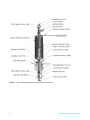
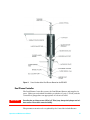
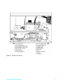
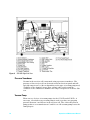
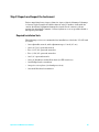
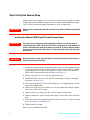
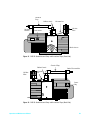
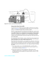
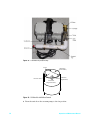
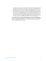
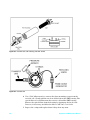
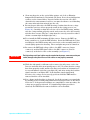
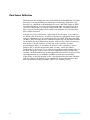
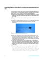
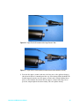
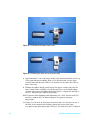
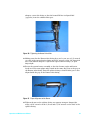
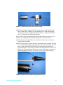
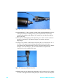
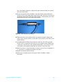
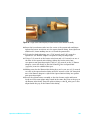
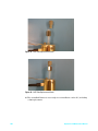
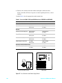
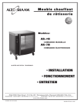
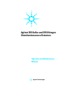
Assembling the Dual Plasma Burner for Component Replacement with the
SCD
The following procedure can be used to assemble the Dual Plasma Burner for
use with the SCD or for replacement of Burner components, such as ceramic
tubes. Refer to Figure 1 on page 26 for proper part nomenclature.
1 Slide the 0.066" internal diameter (I.D.) double taper ferrule onto the lower
Burner tube. The tube should extend approximately 2 mm past the end of
the ferrule.
2 Insert the lower Burner tube and double taper ferrule into the Burner inlet
fitting.
3 Slide the 1/4" Burner adapter over the top of the lower Burner tube all the
way down to the Burner inlet fitting and screw it onto the fitting
finger-tight.
Figure 25 Ferrule Placement on Lower Burner Tube
4 Slide a 1/4" Swagelok nut over the Burner adapter and then slide a 1/4"
ferrule over the Burner adapter and position it into the 1/4" nut. Note: If a
graphite ferrule is used, a small amount of shavings may be created and
some graphite will be left on the tube surface; this is normal. Avoid allowing
any shavings to fall inside a tube.
5 Center the lower Burner tube so that it will slide into the tapered union.
Insert the lower end of the tapered union fitting into the 1/4" Swagelok nut
and screw it on finger-tight. If necessary, the brazed H2 line can be gently
bent out of the way, however, be careful not to stress the brazed (welded)
connection.
6 Insert the large ceramic tube into the quartz heater assembly. Position a
1/4" ferrule (flat end butted up against the top of the swivel nut) onto the
large ceramic tube. With the ferrule positioned against the swivel nut,
approximately 0.5 cm of the large ceramic tube should extend outside of the
nut. Insert the lower Burner tube into the center of the large ceramic tube
and finger tighten the heater swivel nut onto the tapered union fitting.
90
Operation and Maintenance Manual