1
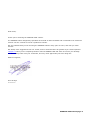
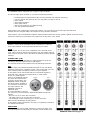
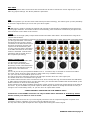
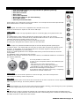
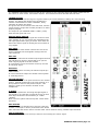
AIRMATE-manual-usb.doc
AIRMATE-USB
MANUAL
V 1.00
Dear Client,
Thank you for choosing the AIRMATE-USB console.
The AIRMATE-USB is designed by specialists in the field of radio broadcast and is intended to be used as an
24 hour "On-Air" console as well as a production console.
We are confident that you will be using the AIRMATE-USB for many years to come, and wish you much
success.
We always value suggestions from our clients, and we would therefore be grateful if you could respond to
[email protected] when you are completely familiar with the AIRMATE-USB and want us to know your findings.
We will certainly learn from your comments, and very much appreciate your time doing this.
With kind regards,
Duco de Rijk
President
AIRMATE-USB manual page: 2
1.INTRODUCTION
The AIRMATE-USB is equipped with 3 types of input modules.
The first 4 triple input modules (1-4) have the following features
*
*
*
*
*
*
*
Professional low noise balanced Mic pre-amp with 48 volt phantom powering.
Two line inputs with optional R.I.A.A. plug able pre-amp on line-B
Gain control
Three band equalizer
Start (ON) switch
Stereo CUE switch for pre fade listening
100 mm professional faders.
Input module 5-6 is identical to triple input module 1 to 4 except for the line-B input that has been
transformed into a digital USB in and output to easy interface with PC’s.
Input module 7-8 are dedicated Telephone Hybrid modules with built in high quality Hybrids and have at the
same time stereo line inputs when one Hybrid can do the job in your studio.
2. TRIPLE INPUT MODULES 1-4
Module 1-4 have three selectable inputs, therefore it is called a
triple input module. A Mic input and two stereo line inputs.
GAIN
With the gain, the source level is adjusted to the internal mixer
level. This is for both the Mic input and the two line inputs with the
same control. Mic gain can be increased by 20dB by internal jumper
settings.
STEREO LINE (A B)
The stereo line inputs (A and B) are high impedance inputs for
connecting play-out systems and or CD players.
The controls of the input modules have the following functions.
MIC
The Mic input is a professional balanced input circuit with 48volt
phantom powering for condenser mikes , this means that you now
have a studio-class microphone-channel at your disposal.
A microphone is an instrument that turns acoustical signals in
electrical ones, without any amplification (in most cases).
These very small signals
have to be amplified without
any noise and interference
from the mixing table. The
AIRMATE-USB is equipped
for this purpose. Instead of
one sensitive connection at
the input channel, the
AIRMATE-USB has a
balanced input.
It is now possible to connect
the 2 wires in your microphone cable to the balanced input as
follows:
- One wire to pin 2 of the XLR connector.
- The other wire to pin 3 of the XLR connector.
- The shielding on the remaining pin 1 of the connector.
What are the advantages of this system?
A microphone cable connected in this way is completely insensitive
for outside interference.
EQUALIZER
The module has a three band equalizer to control the high, mid
and low frequencies individually on carefully chosen frequencies.
AIRMATE-USB manual page: 3
AUX SEND
Below the Equalizer there is the stereo Aux send that can be set to send stereo source signals pre or post
fader by jumper settings. The factory default is post fader.
CUE
Below the equalizer you see the stereo CUE switch (Pre Fade Listening), this switch gives you the possibility
to check the signal before you mix it with your other signals .
ON
The ON switch is used to activate the module and generate a start signal for turntables and CD players as
well as jingle machines. This switch sends out a momentary pulse or shortens continuously two pins of the
Start connector on the back of the console.
FADER
Final control is the high quality K-Alps channel fader with fader start switch. All channels have long throw
100mm stereo faders.
At the beginning of the fader movement you will feel an internally built in start switch that is activated when
you bring up the fader. This switch
activates the start circuitry that is
connected to the Start Connector on
the back. CD players and play out
systems can be activated by this
circuitry. Also Red light is activated
if the SELF OP switch in the master
section is activated. Control Room
monitoring will be muted when a
Mic is opened (DJ setting).
INPUT CONNECTORS
On the back of your AIRMATE-USB
you find seven connectors.
The Mic input has already been
discussed, as this is the balanced or
symmetrical microphone input, the
Other two are the stereo line
inputs.
For Line B you can buy an optional available R.I.A.A. correction amp to be able to connect turn tables.
The level can be set by the gain control to match with every available cartridge.
For your info, this is an identical input as Line A.
The Cinch connector with LEFT printed is the left input and the other one is the right input.
The shield needs to be connected to the ground.
The START switch has two active connections to be wired. The tip and ring are shorted when the ON switch
or fader switch is activated. Once you have done this, you can start the turntable with the ON switch (if the
START connector is wired on the back panel).
These switches quick start turntables through the remote jack by a continuous contact action at the back of
the mixer. If your turntable only needs a pulse to start ask your dealer to modify the internal circuitry to
change it into a momentary action, so you can use it as a pulse start switch.
*NEVER CONNECT THE MAINS TO THIS REMOTE-JACK*
Connections on the START connector can only be made with a maximum of 24 Volts by 50 mA.
Please contact your dealer in case of doubt.
INSERT
This stereo jack connector let’s you insert signal processors such as compressors/gates or special voice
processing units to “upgrade” your voice to be the ultimate DJ voice.
The Tip of the stereo jack accepts the return signal and the Ring the sends a signal.
AIRMATE-USB manual page: 4
SPECIAL AVAILABLE OPTIONS ON MODULE 1 TO 4
On the input PCB of your AIRMATE-USB are several jumpers that can be changed to enable different
configurations of the channel settings.
We advise to have this done by your local dealer if the need arises.
The following 7 jumper settings can be changed to adjust the Airmate-USB to your needs.
1
2
3
4
5
J12-13
J3
J15
J6/16
J7
6
J17
7
J5
R.I.A.A. correction amp PCB can be inserted on Jumper J12 and J13.
Low cut filter on Mic input only by shorting all 4 pins on Jumper J3.
48 volt phantom power on/off via Jumper J15.
Stereo Aux send pre or post selectable via Jumper J6/16 (post is default).
Clean-Feed (CLN-FEED) jumper (J7) to select whether the audio stereo signal
(summed to mono) is send to the clean-feed bus that is available in the master section
for connection external Hybrids.
Pulse/continuous Jumper J17 to change the start pulse from latching (continuously) to
pulse.
Mic gain ( Jumper J5) can be set to amplify an extra 20dB to 40dB.
AIRMATE-USB manual page: 5
3. USB-LINE MODULE 5 AND 6.
*
*
*
*
*
*
*
*
Low noise balanced Mic pre-amp with 48 volt phantom powering.
One stereo line input
One USB connection
Gain control
Three band equalizer
Stereo CUE switch for pre fade listening
Start (ON) switch
100 mm professional fader.
Input module 5-6 is identical to triple input module 1 to 4 except for the line-B input that has
been transformed to a USB in and output.
GAIN
With the gain, the source level is adjusted to the internal mixer level.
This is for both Mic/Line inputs as well as the USB input.
LINE - USB
The stereo line input is a high impedance input for connecting play-out systems and or CD
players.
The USB position of this switch changes this module into a USB in and out module.
It is an input that can be connected to any standard USB connector on PC’s to make an easy
interface with music programs running on the PC.
The controls of the input modules have the following functions.
A small green led lights when data is send over the USB cable.
MIC
The Mic input is a professional balanced input circuit with 48volt phantom powering for
condenser mikes , this means that you now have a studio-class microphone-channel at your
disposal. A microphone is an instrument that turns acoustical signals in electrical ones,
without any amplification (in most cases).
These very small signals have to be amplified without any noise and interference from the
mixing table.
The AIRMATE-USB is equipped for this purpose.
Instead of one sensitive connection at the input channel, the AIRMATE-USB has 2 connections
per channel (balanced).
It is now possible to connect the
2 wires in your microphone cable to the balanced input
as follows:
- One wire to pin 2 of the XLR connector.
- The other wire to pin 3 of the XLR connector.
- The shielding on the remaining pin 1 of the connector.
What are the advantages of this system?
A microphone cable connected in this way is completely
insensitive for outside interference.
EQUALIZER
The module has a three band equalizer to control the high, mid and low frequencies
individually on carefully chosen frequencies.
AUX SEND
Below the Equalizer there is the stereo Aux send that can be set to send stereo source signals pre or post
fader by jumper settings. The factory default is post fader.
CUE
Below the equalizer you see the stereo CUE switch (Pre Fader Listening), this switch gives you the possibility
to check the signal before you mix it with your other signals .
ON
The ON switch is used to activate the module and it generates a signal that can start turntables and CD
players as well as jingle machines. This switch send out a momentary pulse or switches continuously inside
the Start connector on the back of the console.
AIRMATE-USB manual page: 6
FADER
Final control is the 100mm channel fader, this is the actual control to mix the signals.
All channels have long throw 100mm stereo faders.
At the beginning of the fader movement you will feel an internally built in start switch that is activated when
you bring up the fader. This switch activates the start circuitry controls externally connected (via the Start
Connector on the back) devices such as CD players etc.
INPUT CONNECTORS
On the back of your AIRMATE-USB module 5 and 6 you find five connectors.
Two unbalanced stereo line Cinch connectors for connecting CD players or a playout system. Any line level equipment can be connected here.
The level can be set by the gain control to match every source level.
The left cinch connector is the left input and the right Cinch connector is the right
input.
The shield needs to be connected to the ground.
The USB connector is wired according to international standards and is a stereo
USB1.1 Codec (HID Interface) digital input, as well as an output.
The START switch has two active connections to be wired. The tip and ring are
shorted when the ON switch or fader switch is activated.
Once you have done this, you can start the turntable with the ON (if connected to
the START connector) switch on the back panel.
These switches quick start turntables through the remote jack by a continuous
contact action at the back of the mixer. If your turntable only needs a pulse to
start ask your dealer to modify the internal circuitry to change it into a momentary
action, so you can use it as a pulse start switch.
*NEVER CONNECT THE MAINS TO THIS REMOTE-JACK*
Connections on the START connector can only be made with a maximum of
24 Volts by 50 mA. Please contact your dealer in case of doubt.
The balanced Mic input is on XLR and can provide 48volt phantom powering.
SPECIAL AVAILABLE OPTIONS IN YOUR AIRMATE-USB MODULE
On the input PCB of your AIRMATE-USB module there are several jumpers that can be changed to enable
different configurations of the channel settings.
We advise to have this done by your local dealer if the need arises.
The following 7 jumper settings can be changed to adjust the Airmate-USB to your needs.
1
2
3
4
5
J12-13
J3
J1
J6/16
J7
6
J17
7
8
J5
J28-32
R.I.A.A. correction amp PCB can be inserted on Jumper J12 and J13.
Low cut filter on Mic input only By shorting all 4 pins on Jumper J3.
48 volt phantom power via Jumper J15.
Stereo Aux send pre or post selectable via Jumper J6/16 (post is default).
Clean-Feed (CLN-FEED) jumper (J7) to select whether the audio stereo signal
(summed to mono) is send to the clean-feed bus that is available in the master section for
external Hybrids.
Pulse/continuous Jumper J17 to change the start pulse from latching (continuously) to
pulse.
Mic gain ( Jumper J5) can be set to amplify an extra 20dB or 40dB.
USB output selection
AIRMATE-USB manual page: 7
4. TELCO-LINE MODULE 7-8
Input module 7-8 are dedicated Telephone Hybrid modules with built in high quality
Hybrids and also have stereo line inputs in case one Hybrid is only needed.
Highlights are:
*
*
*
*
*
*
*
*
*
High quality Hybrid circuit to directly connect to phone lines
Extra stereo line input
Gain control
Telco send Control
Direct access CONNect and Talk Back switches
Stereo Aux send
Stereo CUE switch for pre fade listening
Start (ON) switch
100 mm professional fader.
WHAT IS A TELEPHONE HYBRID?
Telephone hybrids are interfaces between professional audio equipment and public
telephone networks. They provide protection for your equipment and the public telephone
lines, allowing for various line signals and line conditions. Automatically canceling out the
unwanted signal they also facilitate two-way communication down a single telephone line.
Each Airmate-USB hybrid module has a telephone line (WALL) connection and a handset
connection.
A large proportion of D&R hybrids (also built into this Airmate-USB) are used in radio and
television broadcasting applications allowing external callers to be connected to the studio
mixing console. Most of the units are supplied to radio stations allowing extremely
effective conversion between 4-wire audio circuits and standard telephone lines.
Specs:
Output
Input
R/C balance
Separation
:
:
:
:
Internally connected in the Airmate.
Line level 0 dBu balanced, internally connected in the Airmate.
fully adjustable.
more than 30dB.
The controls of the Hybrid/Line modules have the following functions.
TELCO SEND
With this control you can adjust the level of the outgoing signal to the telephone line.
TELEPHONE-LINE SWITCH
When switched to the stereo line input you have a high impedance line level input for
connecting play-out systems or CD players.
The up position of this switch changes this module into a full blown telephone Hybrid
module. It is a Hybrid that can be connected to any standard telephone line.
R-BALANCE
Internal potentiometer to adjust for maximum side tone attenuation.
C-BALANCE
16 position rotary switch to select the optimum side tone attenuation.
GAIN
With the gain, the source level is adjusted to the internal mixer level.
This is for both the Telephone Line input and the Line input.
CONNECT
This switch (when pushed) picks up the phone line when a call comes in.
Note: the incoming call will not be heard yet, this is only possible when the CUE switch is
pushed or the ON switch and the fader are activated.
TALKBACK
By pushing the TB switch in the Hybrid module the internal talkback microphone is
activated and allows you to talk to the caller without being ON-Air.
AIRMATE-USB manual page: 8
AUX SEND
Below the TB switch there is the stereo Aux send that can be set to send stereo source signals pre or post
fader by jumper settings. The factory default is post fader.
RING (LED)
This Led lights when a call comes in to alert you.
CUE
Below the equalizer you see the stereo CUE switch (Pre Fader Listening), this switch gives you the possibility
to check the signal before you mix it with your other signals .
ON
The ON switch is used to activate the module and generate a signal to start turntables and CD players as
well as jingle machines. This switch send out a momentary pulse or switches continuously to the Start
connector on the back of the console. In case of the Hybrid module any other function you think is worth
happening can be activated.
FADER
Final control is the 100mm channel fader, this is the actual control to mix the input signals.
All channels have long throw 100mm stereo faders.
At the beginning of the fader movement you will feel an internally built in start switch that is activated when
you bring up the fader. This switch activates the start circuitry, it can control externally connected (via the
Start Connector on the back) devices such as CD players etc.
INPUT CONNECTORS
On the back of your AIRMATE-TELCO module 7 and 8 you
find five connectors.
Two unbalanced stereo line Cinch connectors for connecting
CD players or a play-out system. Any line level equipment
can be connected here.
The level can be set by the gain control to match nearly
every source level.
One cinch connector is the left input and the other Cinch
connector is the right input.
The shield needs to be connected to the ground.
The START switch has two active connections to be wired.
The tip and ring are shorted when the ON switch or fader
switch is activated.
Once you have made this connection to your CD player, you
can start the CD player with the ON switch on the front
panel (or with the fader when the On switch is on).
These switches quick start CD/turntables through the
remote jack by a continuous contact action at the back of
the mixer. If your CD/turntable only needs a pulse to start
ask your dealer to modify the internal circuitry to change it
into a momentary action, so you can use it as a pulse start
switch.
The two RJ11 connectors are there to connect the Module to the companies phone line connection (Wall) and
to connect your telephone appliance (Phone) to be able to dial listeners.
Connections on the START connector can only be made with a maximum of 24 Volts by 50 mA.
Please contact your dealer in case of doubt.
*NEVER CONNECT THE MAINS TO THIS REMOTE-JACK*
AIRMATE-USB manual page: 9
SPECIAL AVAILABLE OPTIONS IN YOUR AIRMATE-TELCO MODULE
On the input PCB of your AIRMATE-USB MODULE there are several jumpers that can be changed to enable
different configurations of the channel settings.
We advise to have this done by your local dealer if the need arises.
The following 4 jumper settings can be changed to adjust the Airmate-USB Telco modules to your needs.
1
2
J6/16
J7
3
J17
Stereo Aux send pre or post selectable via Jumper J6/16 (post is default).
Clean-Feed (CLN-FEED) jumper (J7) to select whether the audio stereo signal
(summed to mono) is send to the clean-feed bus that is available in the master section
for external Hybrids.
Pulse/continuous Jumper J17 to change the start pulse from latching (continuously) to
pulse.
CONNECTION WIRING OF BOTH (Wall) LINE and PHONE RJ-11 CONNECTORS
PHONE/WALL RJ-11
Pin 1
Pin 2
Pin 3
Pin 4
FUNCTION
n.c.
A (telephone line)
B (telephone line)
n.c.
CONNECTION
In/out
In/out
AIRMATE-USB manual page: 10
5. MASTER SECTION
The AIRMATE-USB master section houses all the controls for the summing amps and master inputs such as
Aux return, 2-Track return, and master outputs. All individual functions we shall describe here.
LEDBAR METERS
The master section has two large 21 segment meters (VU meter Ballistics) reading all in and outgoing
signals. The attack and release time constants are
conform international VU meter standards, being
300mSec for attack and decay.
The green area in the led bar is the safe area, and the
yellow area the range that normally would be on when
properly aligned.
The output of your AIRMATE-USB is +4dBu (1.22v)
when the last green led is on.
MASTER MONO SWITCH
This switch turns the stereo signal into mono for both
main outputs. It is a convenient way of balancing the
left right signal before going to stereo. Also when one
side of the stereo signal is missing the mono switch is
very helpful.
AUX SEND
The stereo Aux send master controls the sum of the
entire individual Aux send signals coming from the
input channels.
AUX CUE
The Aux cue redirects the master output signal and led
bar indication to the Aux output that gives you the
total outgoing signal of the Aux master.
It is necessary to turn the master control up to have
an outgoing signal.
MONITOR
The monitor control is fed by the master outputs pre
master fader.
It is an extra stereo output for another sound system
or recording device.
FOLLOW PHONES
This switch actually is an input selector for the monitor
output. Instead of listening to the main outputs, it is
also possible to listen to the phones output. This
feature is used by DJ's that do not want to use
headphones.
2-TRACK
This switch replaces the incoming left/right signal or
Cue signal by an externally connected source on the 2
track input connectors. Its sensitivity is -10dBv
(300mV).
Note: The Cue system will interrupt the 2 track when
activated.
AUX RETURN
This stereo input is intended to be used for returning
reverbs. This input is directly connected to the stereo
main mix buss and can be used to connect other mixers without loosing valuable input channels.
CUE AUX RETURN
This switch enables you to stereo pre listen to an incoming Aux return signal.
AIRMATE-USB manual page: 11
BALANCE
The balance knob controls the balance between the main stereo output and the stereo Cue signal when
selected.
Note: The split switch de-activates the balance control.
With the balance control anywhere between Cue and L/R you always have control over the main output
signal even when a Cue switch is activated.
SPLIT
When the split function is activated the following listening situation is created.
The left side of the phones output gives the summed Cue signal and the right output gives the summed
left/right signal (pre fader). The balance control has no influence on this configuration anymore.
PHONES
The phones output (located on the front panel) has an automatic input selector.
Normally the left/right output is heard until a Cue switch is activated anywhere in the console that
immediately takes over the left/right signal. The led bar switches accordingly with this action.
We advise you to use headphones with an input impedance not lower than 400 Ohm to avoid distortion.
An 8 Ohm headphone will produce lots of distortion when cranking up the level due to its low impedance
load. It is a load equivalent to the load that loudspeakers normally present to power amps and as you know
the AIRMATE-USB is no power-amp, sorry.
MASTER FADERS
The AIRMATE-USB master faders are 60mm models controlling both left and right signals individually to
compensate for imbalances in the audio signals.
SELF-OP
This switch mutes the monitor output (your control room monitor) as soon as a microphone input is opened.
At the same time a relay is activated which is connected to the Red Light output connector.
CLEANFEED OUTPUT
The Clean feed output sums all signals coming from the input modules (except for those inputs where
jumper J7 is not activated). Clean feed signals are equivalent to Aux send signals, but are always post fader.
By jumpering only those channels that are not returning Telephone Hybrid signals you avoid feedback and
have a perfect set-up for talk shows. The Clean feed output is only used when an external Hybrid is used.
CLEANFEED
All outgoing signals from the Clean feed output can be monitored by way of the Cue switch.
ANNOUNCER OUTPUT
In the up position of the "follow phones" switch, the input of the announcer is fed by the main left/right
signal pre master fader. In the depressed mode of the "follow phones" switch the Announcer output is fed by
the same signal as the phones output is.
FOLLOW PHONES
This switch is the input selector of the announcer output, see above description.
TALK BACK
The Talkback circuit has a built in electret microphone with extensive routing to most of the outputs.
By selecting one or more of the routing switches
you can communicate to the outputs.
The Talkback level is independent upon settings
of the master controls of the Clean feed and
Announcer outputs. It is however subjected to
the master level of the master Aux output
control. The Talkback switch has a momentary
action to avoid being unwillingly in the talkback
mode.
MASTER CONNECTORS
The master connector panel houses 12 Cinch
connectors 2 jacks and 2 male XLR connectors
where all interfacing takes place. Furthermore
the mains connector with integrated fuse holder
is located in this section.
A ground terminal completes the back panel
connector section.
AIRMATE-USB manual page: 12
TAPE OUTPUTS
The first connectors on the left are the tape output connectors for left and right for connecting an audio
recorder. Output level is -10dBv (300mV), the signal is pre master fader.
CLEANFEED OUTPUTS
Direct beneath the Tape outputs are the Clean feed cinch connectors.
RED LIGHT
Direct beneath the Clean feed cinch connectors is a stereo jack (Mic On) that can control a red light
indicator. This stereo jack is connected to a change over relay. This relay is capable of controlling external
Red light circuits as long as it does not take a higher voltage than 24 volt and the current does not exceed
50mA!
NEVER CONNECT 220 VOLT AC TO THIS JACK!!
The C.C. (Center Contact) of the internal relay is connected to the Tip of the stereo jack.
The N.O. (Normally Open) contact is connected to the ring of the jack.
The N.C. (Normally Closed) contact is connected to the "ground" of the jack.
AIRMATE-USB RED LIGHT CONNECTION
AUX RETURN
Right from the tape connectors you see the Aux return connectors. These inputs are controlled by the Aux
return knob. The signal is directly connected to the master main mix busses. You can connect reverb
returns or other stereo signals without using any input module. The input level should -10dBv as a
minimum.
AUX OUTPUTS
The aux outputs are on two Cinch connectors providing you with the signal coming from the aux sends in the
channels.
The level is +4dBu (1.22 volt).
You can connect inputs from reverbs to these Cinch connectors or use it as a monitor output, when you have
jumpered the Aux send in the channels pre fader.
AIRMATE-USB manual page: 13
2-TRACK INPUTS
These inputs are intended to return stereo machines in the monitor section.
Such as signals from master recorder/tuners etc. The level needs to be -10dBv (300mV) as a minimum for
optimum signal to noise.
MASTER OUTPUTS
The master outputs are on male 3 pin XLR connectors in a ground compensated arrangement. Ground
compensated means that all advantages of balancing are maintained when connected to a balanced input of
a power amp, professional recorder or On-Air processor. The output level is +4dBu (1.22 volt).
GROUND CONNECTOR
This terminal is intended for grounding Phono players or it is to be used as central ground pin in complex
set-ups.
MAINS CONNECTOR
The mains inlet is a euro type connector with built in fuse. Your AIRMATE-USB can accept voltages between
210 volts and 230 volts 50/60Hz.
The built in fuse is a slow blow type of 1 Amp. never replace this fuse by higher values.
In case of 115 volt local power the value of the fuse needs to be increased to 2 Amps and your local dealer
has to rewire the internal transformer wires.
AIRMATE-USB manual page: 14
6. SETTING UP ROUTINES MODULE 1-4
-
Connect a power-amp, recorder or transmitter to the left/right outputs.
Connect a high impedance headphone to the "phones"-jacks on the front.
Connect the microphones as described.
Act like wise with turntables, CD players and jingle machines.
You can eventually connect a D&R Telephone Hybrid to the Clean feed output.
Be sure that Jumper J7 is on position 3-4 to avoid feedback when returning the Telephone
Hybrid output on these channels.
- Connect a red light indicator when there is a need for it.
- The Announcer output can feed a high impedance headphone directly.
- Now that everything is connected, follow the adjustment procedure.
Note; for mikes, only activate the grey Mic switch, for line level leaves this switch up and select line A or B
- Put on your headphones and turn the headphone-volume control to "12 o'clock" position.
- Turn all the gain-controls and the master-control to the left.
- Set all equalizer-controls to the "12 o’clock” position.
- All pushbutton-switches should be in the up position. (See above).
- Switch on the power-supply, the first led in the led bar should be on.
SETTING UP AN INPUT CHANNEL
•
•
•
•
•
•
•
•
•
•
•
•
Push the CUE switch in a channel that is connected to a source.
Now slowly turn the GAIN control clockwise until you hear and see the input signal on the led bars in
the master section.
You can change the input sound by adjusting the equalizer-section.
If you have adjusted the equalization, once again check the level on the led bar, because
increasing specific parts of the frequency spectrum can easily add more gain to the signal.
If you cannot get enough gain (when you have a low sensitivity dynamic microphone) the jumper s
on J5 should be removed to get an extra 20dB of gain
The led bar indication has to be between 0 dB and +6 dB (the yellow area) to get a proper
level on amplifiers or recording devices.
The led bar is a VU meter indicating the absolute level that enters the console.
It is calibrated to indicate 0 dB on the scale corresponding with a +4dBu output level.
Release the CUE switch so the led bar now reads the output signal again.
Now push the ON button to connect the input signal to the fader.
Now fade to the "8" position screened alongside the channel faders and fully turn up the
master fader. Further volume adjustments have to be realized on the power-amp/transmitter.
The other inputs are likewise adjusted, using the "CUE" switches to pre fader listen the
connected sources and usage of the input gain for precise adjustments.
Be carefully not to place the AIRMATE-USB near heavy power transformers, as used in power amps etc, this
may cause hum, in spite of the thick metal frame.
7. SETTING UP THE USB MODULES
All that is said about modules 1 to 4 is also applicable for module 5 and 6 apart from the fact that in these
modules line B is replaced by an USB interface.
To be able to set up a connection with your PC use a readymade cable from
the local computer shop that has on one end the house type USB connector
and on the other side the flat one that PC’s can accept. (See picture)
By connecting the Airmate-USB to your PC the PC will recognize the Airmate
as new hardware and will establish a connection to the right program.
No need to download drivers, no complicated setup routines, just plug in the
USB cable into your Windows or Mac computer and start tracking!
If you first want to know more about USB try this link
http://en.wikipedia.org/wiki/Audio_Stream_Input/Output
If you’re pretty more familiar with audio recording, the latest versions of
Kristal Audio Engine and Audacity are available free of charge — just type in the following link in your
internet browser http://www.asio4all.com/ and start downloading.
AIRMATE-USB manual page: 15
8. SETTING UP THE TELCO MODULES
Connect the two wires of the telephone line’s wall unit to the RJ-11 connector labeled wall (LINE) and
connect the telephone appliance itself to the RJ-11 connector labeled PHONE. Note that to originate calls, a
local phone must be connected to the Airmate-usb.
Now the internal hybrid is interfaced (fully balanced) between your
telephone appliance and its connection to the outside world. The hybrid
can now split the send and return signals.
Position both Telco send and gain potentiometers in the 12 o’clock
positions
If a local phone is connected, originate a call to a remote side. If no
local phone is present, someone at a remote site must call you.
When a call comes in the red LED called ring (positioned in between
CUE and ON) lights up red in the rhythm of the ring.
The line is picked up by pushing the CONN button.
If you want to hear the caller press the CUE button to listen to the incoming call.
Adjust the Gain control to get a good input level from the telephone line.
To be able to talk to the caller press the TB (Talkback) button and… talk to him.
Adjust the Telco send potentiometer to increase or decrease the outgoing level to the caller.
Note: This is all happening outside the broadcast.
If all is Ok and both parties know what to do then you can activate the ON switch and fade up the caller ONAIR. Or… put the fader in its 0 position and activate the ON switch to On-Air the caller.
But… before you are in this situation you will have to adjust the optimum RC balance to create the best
separation of in and outgoing signal to the telephone line, otherwise your listeners will be presented with
bad quality audio. Adjustments are only needed once when installing the Airmate-USB.
To achieve the optimum attenuation you need to adjust the C and R balance first.
This is how it is performed:
1. Check if the Telephone connection is established and all connections to the mixing console are
correctly wired.
2. Send an audio signal to the telephone line by activating another module, for instance a CD player.
3. Now activate the CUE button of the TELCO module where the telephone line is connected to.
4. You will faintly hear the send signal coming out of the mixing console.
5. Adjust the R-Balance for minimum feed through of the mixers send signal.
6. Listen now which switch position of the C-balance gives a further reduction of the return signal.
7. Maybe it is good to re-adjust the R-balance after having selected another switch position.
8. Repeat steps 5 and 6 until no further improvement is achieved for this telephone line.
9. Note that when you use the mixer on different locations this procedure has to be done all over
again.
9. SUMMERY
We hope this manual has given you sufficient information to fully enjoy this new AIRMATE-USB mixer.
If you require more info please contact your local dealer or in case he/she is not able to help you send us a
mail at [email protected]
In case you have bought this mixer from a previous owner, check out the dealer in your area on our website
www.d-r.nl in case you need assistance.
AIRMATE-USB manual page: 16
10. TECHNICAL SPECIFICATIONS
MIC INPUTS
XLR connector balanced impedance 2 kOhm.
sensitivity -60dBu.
Pin 1 = ground.
Pin 2 = hot (in phase).
Pin 3 = cold (out of phase).
+48 volt phantom
INSERT
Stereo jack.
Tip=Input (connect to output of signal processor)
Ring=Output (connect to input of signal processor)
Ground=shield
LINE A/B
Cinch connector, sensitivity -20dBu to +20 dBu.
sleeve =ground.
DISC INPUTS
On B inputs only when optional R.I.A.A. pre-amp is installed.
47kOhm, 0.5 mV to 10 mV.
START REMOTE
Stereo jack, Tip is a change over contact between sleeve and ring.
NOT FOR 110/220 VOLT SWITCHING!!!!!!!
It can only switch 24V/50mA max!
MASTER OUTPUT CONNECTORS
MAIN
XLR male connector for left and right.
pin 1 = ground.
pin 2 = in phase.
pin 3 = out of phase. (ground compensation circuitry, 45 Ohm)
output level = +4dBu/100Ohm.
TAPE
Two cinch connectors for left and right.
-10dBv (300mV) /10kOhm.
Sleeve=ground.
2 TRACK INPUTS
Cinch connectors.
-10dBv (300mV) / 10kOhm.
Sleeve = ground.
AUX RETURN
Cinch connectors for left and Right.
-10dBv (300mV) / 10kOhm.
Sleeve = ground.
CLEANFEED OUTPUTS
Cinch connectors paralleled
+4dBu (1.22volt) output / 47 Ohm.
Sleeve = ground.
RED LIGHT
Stereo jack connected to internal change over relay.
Center Contact = Tip
Normally Closed = Ground
Normally Open = Ring
ANNOUNCER OUTPUT
Stereo jack for left and right
Tip = left
Ring = right
Sleeve = Ground
AUX OUPTUTS
Cinch connectors (for left and right).
+ 4 dBu (1.22 volt) / 100 Ohm (Sleeve = ground.)
MONITOR OUTPUT
Cinch connectors for left and right.
+ 4 dBu (1.22 volt) / 100 Ohm.
Sleeve = ground.
AIRMATE-USB manual page: 17
PHONES:
Preferable 400 Ohms or higher!
11. TECHNICAL SPECIFICATIONS
INPUTS
HYBRID
OUTPUTS
EQUALIZER
RED LIGHT
OVERALL
Mic input balanced 2 kOhm. Plus 48volt phantom
Mic noise -122 dBr (A-weighted).
Sensitivity: -70dB min, 0dB maximum.
Line inputs: unbalanced, 10kOhm, Cinch gain range 40dB.
Phono inputs: unbalanced, 47kOhm, 1-10 mV.
2 Track return: -10dBv at 10kOhm.
Aux return: -10dBv at 10kOhm.
Output
Input
R/C balance
Separation
:
:
:
:
Internally connected in the Airmate.
Line level 0 dBu balanced, internally connected in the Airmate.
fully adjustable
more than 30dB. (dependent upon adjustments of RC balance)
Left/Right/Monitor/Aux: +4dBu (1.55volt) at 47 Ohm.
Tape output: -10dBv at 1kOhm.
Headphone: 400-600 Ohm, 500mW.
High: +/- 12 dB at 12kHz shelving curve.
Mid: +/- 12 dB at 1 kHz bell curve.
Low: +/- 12 dB at 60 Hz bell curve.
Stereo jack connector to intern relay
Center Contact = Tip
Normally Closed = Shield
Normally Open = Ring
Frequency response 10-60.000 Hz (+/- 0.5dB).
Distortion: <0.009% max at 1 kHz.
Dimensions: 483x356x95 mm ( 8HE ) .
Weight: 11 kg.
We wish a you creative and long lasting use of this quality
product of
D&R Electronica Weesp b.v.
Rijnkade 15B
1382 GS WEESP, The Netherlands
Phone:
0294-418 014
Fax:
0294-416 987
Website:
http://www.d-r.nl
E-mail:
[email protected]
AIRMATE-USB manual page: 18
12. OPTIONS/MODIFICATIONS
Modification AIRMATE-USB (stereo AUX) from 220V to 110V
BE CAREFUL!
THE AIRMATE-USB POWER PCB IS
CONNECTED TO HIGH VOLTAGE!
REMOVE POWER CABLE BEFORE
SERVICING!
Modifications can only be done by classified persons!
The following picture displays the 220V wiring. Green and White are connected to each other and Red and
Yellow are connected to connector J1.
To modify the power-supply there are two necessary steps to follow.
1)The power-cabling to the transformer needs to be rerouted.
2)The fuse needs to be replaced.
Step 1: Rerouting the power-cabling.
Twist the Green and the Red wire together.
Twist the White and the Yellow together.
Then connect both wires to the connector J1.
The red indicator (arrow) specifies the point ( 2 holes) where the wires need to be mounted to the Print
Circuit Board with a tie-wrap.
AIRMATE-USB manual page: 19
Step 2: Replacing the fuse.
The fuse-box is integrated in the AC socket. The fuse must be replaced from a 0.5A to a 1A.
Make sure the 230V marking on the fuse-holder is on TOP!!! Else the device will not function.
AIRMATE-USB manual page: 20
13. ELECTROMAGNETIC COMPATIBILTY
This unit conforms to the Product Specifications noted on the Declaration of Conformity.
Operation is subject to the following two conditions:
•
•
•
•
This device may not cause harmful interference
This device must accept any interference received, including interference that may cause
undesired operation
Operation of this unit within significant electromagnetic fields should be avoided
Use only shielded interconnecting cables.
14. DECLARATION OF CONFORMITY
Name Manufacturer
Address manufacturer
D&R Electronica Weesp b.v.
Rijnkade 15B,
1382 GS Weesp,
The Netherlands
declares that this product
Name product
Model number
Product options
AIRMATE-USB
n.a.
none
passed the following product specifications:
Safety
IEC 60065 (7th ed. 2001)
EMC:
EN 55013 (2001+A1)
EN 55020 (1998)
Supplementary Information:
The product passed the specifications of the following regulations;
Low voltage 72 / 23 / EEC
EMC-Directive 89 / 336 / EEC. as amended by Directive 93/68/EEC
(*) The product is tested in a normal users environment.
AIRMATE-USB manual page: 21
15. PRODUCT SAFETY
This product is manufactured with the highest standards and is double checked in our quality control
department for reliability in the "HIGH VOLTAGE" section.
CAUTION
Never remove any panels, or open this equipment. No user serviceable parts inside.
Equipment power supply must be grounded at all times.
Only use this product as described, in user manual or brochure.
Do not operate this equipment in high humidity or expose it to water or other liquids.
Check the AC power supply cable to assure secure contact.
Have your equipment checked yearly by a qualified dealer service center.
Hazardous electrical shock can be avoided by carefully following the above rules.
EXTRA CAUTION FOR LIVE SOUND
Ground all equipment using the ground pin in the AC power supply cable. Never remove this pin.
Ground loops should be eliminated only by use of isolation transformers for all inputs and outputs.
Replace any blown fuse with the same type and rating only after equipment has been disconnected from AC
power. If problem persists, return equipment to qualified service technician
PLEASE READ THE FOLLOWING INFORMATION
Especially in sound equipment on stage the following information is essential to know.
An electrical shock is caused by voltage and current, actually it is the current that causes the shock.
In practice the higher the voltage the higher the current will be and the higher the shock.
But there is another thing to consider and it is resistance. When the resistance in Ohms is high between two
poles, the current will be low and vice versa.
All three of these; voltage, current. and resistance are important in determining the effect of an electrical
shock.
However, the severity of a shock primarily determined by the amount of current flowing through a person.
A person can feel a shock because the muscles in a body respond to electrical current and because the heart
is a muscle it can affect, when the current is high enough. Current can also be fatal when it causes the chest
muscles to contract and stop breathing. At what potential is current dangerous.
Well the first feeling of current is a tingle at 0.001 Amp of current. The current between 0.1 Amp and 0.2
Amp is fatal.
Imagine that your home fuses of 20 Amp can handle 200 times more current than is necessary to kill. How
does resistance affect the shock a person feels. A typical resistance between one hand to the other in "dry"
condition could well over 100,000 Ohm.
If you are playing on stage your body is perspiring extensively and your body resistance is lowered by
more than 50%. This is a situation in which current can easily flow.
Current will flow when there is a difference in ground potential between equipment on stage and in the P.A.
system. Please do check if there is any potential between the housing of the mikes and the guitar synth
amps, which will be linked by your body on stage. Imagine, a guitar in your hand and your lips close to the
mike! A ground potential difference of above 10 volts is not unusual, in improperly wired buildings it can
possibly be as high as 240 volts.
Although removing the ground wire sometimes cures a system hum, it will create a very hazardous situation
for the performing musician.
Always earth all your equipment by the grounding pin in your mains plug.
Hum loops should be only cured by proper wiring and isolation input/output transformers.
Replace fuses always with the same type and rating after the equipment has been turned off and unplugged.
If the fuse blows again you have an equipment failure, do not use it again and return it to your dealer for
repair.
And last but not least be careful not to touch a person being shocked as you, yourself could also be shocked.
Once removed from the shock, have someone send for medical help immediately
Always keep the above mentioned information in mind when using electrically powered
equipment.
AIRMATE-USB manual page: 22