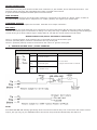
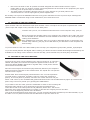
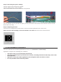
1
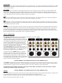
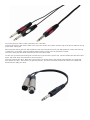
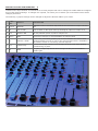
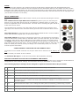
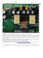
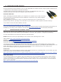
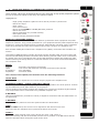
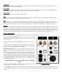
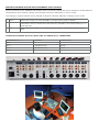
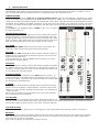
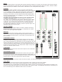
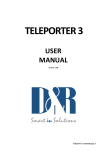
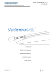
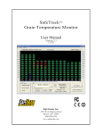
AIRMATE-USB
MANUAL
V 2.07
Dear Client,
Thank you for choosing the D&R AIRMATE-USB mixer.
The AIRMATE-USB was designed by Radio Broadcast professionals along with the D&R design team and is intended
to be used 24 hours per day as an “On-Air” mixer and/or a production console in the most demanding production
room.
We are confident that you will be using the AIRMATE-USB for many years to come, and wish you much success.
We value suggestions from our clients and would be grateful if you could email us with your comments at info@d-r.
nl when you are familiar with the AIRMATE-USB mixer.
We learn from the ideas and suggestions of customers like you and appreciate your time.
With kind regards,
Duco de Rijk
President
1. INTRODUCTION
The AIRMATE-USB has THree types of Modules.
Triple Input Modules (positions 1-4) have the following features
•
•
Professional low noise balanced Mic pre-amp with 48 volt phantom
powering.
Two pairs of line inputs with optional R.I.A.A. equalized pre-amp on
line-B for turntables.
Gain control
Three band stereo equalizer
Start (ON) switch
Stereo CUE switch for pre fade listening
100mm smooth professional faders
•
•
•
•
•
Input modules 5 & 6 are identical to triple input modules 1 thru 4
except for the line-B inputs have been converted into digital USB input
and output to allow easy interface with PC’s (Windows & Macintosh
computers). This feature will allow you to connect to the Internet via
your computer for “Live” streaming of audio to the Internet.
Input modules 7 & 8 have a high quality built-in Telephone Hybrid in
each module which are switch-able to stereo line inputs when only one
or no Telephone Hybrid is needed in your live broadcast studio.
2. TRIPLE INPUT MODULES 1-4
The input modules switches & controls have the following functions:
Each of Modules 1 thru 4 has three selectable inputs. The three types
of inputs consist of a Mic input and two pairs of stereo line inputs. In
the Mic switch position, the module is a normal mono module. When
the Mic is switched out, you have the choice of Line A or B stereo inputs which allows for the module to become a stereo module with both
left & right signals to feed the stereo mix buss.
GAIN
With the gain control, the source input level can be adjusted to the
required internal mixer level. This control adjusts both the Mic input
and the two pairs of line inputs with the same control depending on the
switch positions. Mic gain can be increased by 20dB by internal jumper
settings (if needed).
STEREO LINE (A B)
The stereo line inputs (A or B) pairs are high impedance inputs for connecting the stereo line level outputs of devices such as CD players.
MIC
The Mic input has a balanced XLR input connector with 48volt phantom powering for condenser mikes. The Mic-pre
circuitry uses the latest technology studio-class components. The low-noise design and excellent phase spec that
D&R is known for is integrated throughout the AIRMATE-USB.
Using balanced microphones & cables allows for the quietest and high quality audio signals throughout your Airmate-USB mixer. You can use standard
balanced Mic cables available at any pro audio dealer or music store.
The Airmate uses chassis-mount female XLR type Mic input connectors. Any
standard pro audio Mic cable will have the mating male XLR connector.
EQUALIZER
Each module has a stereo three band equalizer to control the high, mid, and low frequencies individually. The D&R
designers used carefully chosen frequencies in the equalizer circuitry to enhance the Mic input as well as the stereo A & B line inputs.
AUX SEND
The next control is a stereo Aux send that sends stereo source signals to the stereo Aux send buss Master and
then to the output connectors on the Master back panel. The stereo Aux send is for external effects such as reverb, echo, or headphone amplifiers. Each Aux send can be set pre or post fader by changing jumper settings on
the circuit board of each module. The factory default is post fader.
CUE
Below the AUX SEND is the stereo CUE switch (Pre Fade Listening), this switch allows you to check the signal before you raise your channel fader up and mix it with other signals in the mixer.
ON
The ON switch is used to activate the module and generate a start signal for turntables, CD players, and jingle or
cart machines. This switch sends out a momentary pulse or shortens continuously two pins of the Start connector
on the back panel of the console.
FADER
Final control is the high quality, 100mm long throw K-Alps stereo channel fader with integrated fader start switch.
At the beginning of the fader movement you will feel integrated start switch that is activated when you bring up
the fader. This switch activates the start circuitry that is connected to the Start Connector on the module back
panel as described above. A Red light is activated if the SELF OP switch in the master section is activated. Control
Room monitoring will be muted when a Mic is opened (DJ setting).
INPUT CONNECTORS
On the back of modules 1 thru 4, you find seven connectors for each module.
The Mic input is a balanced female XLR type
connector. The two pairs of stereo line inputs use
Cinch pro RCA female type connectors. If you use
turn tables and need phono type R.I.A.A. equalized pre-amps, D&R offers an optional plug-in
R.I.A.A. pre-amp for Line inputs B at a nominal
price. The level can be set with the gain control to
match any available phono cartridge.
Both Line inputs A & B are identical with the exception of the optional phono pre-amp. Being unbalanced, the shield and (-) or common need to
be connected together during installation.
In order to use the START switch, it requires
two pins in the ¼” stereo connector located on
the back panel to be wired. The tip and ring are
shorted when the ON switch or fader switch is
activated. Once you have done this, you can start
a turntable with the ON switch (if the START connector is wired on the back panel).
*NEVER CONNECT AC POWER VOLTAGE TO THIS REMOTE-JACK*
The START switches quick start turntables through the remote jack via a shorted contact action in the ¼” stereo
connector on the back of the mixer. If your turntable only needs a pulse to start, ask your dealer to modify the internal circuitry to change it into a momentary action, so it can be used as a pulse start switch.
Connections on the START connector can only be made with a maximum of 24 Volts 50 mA. Please
contact your dealer if you are uncertain.
INSERT
*NEVER CONNECT AC POWER VOLTAGE TO THIS REMOTE-JACK*
This ring/tip/sleeve stereo jack socket let’s you insert signal processors such as compressors/gates or special voice
processing units to “improve” your voice to be the ultimate announcer/DJ sound.
The Ring of the stereo jack sends the channel signal and the Tip accepts the return signal.
Below you see the type of cable you need.
If you are going to make a cable yourselves, do it like this.
Connect the tip from the stereo cable to the tip of one of the mono jacks and the ring of the stereo cable to the tip
of the other mono jack.
Now insert the stereo jack into the Airmate’s insert and connect the mono jack that produces a hum when the tip
is touched by your finger (and the related channel fader is open) into the processors output.
The other mono jack should be inserted into the processors input.
In case your processor has XLR inputs connect the tip of the stereo jack to pin 2 of the Female XLR and short pin 1
and 3 with each other and connect to ground (sleeve)
This also goes for the other Male XLR, connect the ring of the stereo jack (which sends signals) to a male XLR
pin2. Short here pin 1 and 3 and ty to ground (sleeve). This has to be done because the insert is not balanced.
See below the cable you need.
SPECIAL OPTIONS FOR MODULES 1 - 4
Located on the input channel circuit boards are several jumpers that can be changed to enable different configurations of the channel settings. If changes are required, we advise you to contact your local dealer to have these
changes performed.
The following 7 jumper settings can be changed to adjust the Airmate-USB to your needs.
JUMPERS
DEFAULT
DESCRIPTION
1
J12-13
RIAA NO
Optional R.I.A.A. correction amp PCB can be inserted on Jumper J12 and
J13.
2
J3
Low cut ON
Low cut filter on Mic input done by shorting all 4 pins on Jumper J3.9
3
J15
Phantom ON
48 volt phantom power on/off via Jumper J15.
4
J6/16
POST
Stereo Aux send pre or post selectable via Jumper J6/16
5
J7
Channel 7-8 ON
Clean-Feed (CLN-FEED) jumper (J7) to select whether the stereo audio
signal(summed to mono) is sent to the clean-feed bus that is available in
the master section for connecting external Hybrids.
6
J17
Continuously
Pulse/Continuously Jumper J17 to change the start pulse from latching
(continuously) to pulse.
7
J5
20dB
Mic gain ( Jumper J5) can be set to change the Mic pre from 20dB to
40dB of gain.
3. USB-LINE MODULES 5 AND 6 CONNECTORS, CONTROLS, & FUNCTIONS
* Low noise balanced Mic pre-amp with 48 volt phantom powering.
* One pair stereo line inputs (left & right)
* One USB connector (stereo in & out)
* Gain control
* Three band equalizer
* Stereo CUE switch for pre fade listening
* Start (ON) switch
* 100mm Ultra-Smooth Professional fader.
Input modules 5 & 6 are identical to triple input modules 1 thru 4 except for line-B
input is replaced with a USB (stereo input and output circuit) connector on the back
panel.
GAIN
With the gain control, the source level is adjusted to the required internal mixer level.
This is for both Mic/Line inputs as well as the USB inputs.
LINE - USB
The stereo line input is a high impedance input for connecting any stereo line level
device such as CD players, iPods, tape decks etc. The USB switch changes the module into a USB in and out module. The USB connector will communicate with playrecord devices such as computers using a DAW (Digital Audio Workstation), Windows
Media Player, and/or CD players using a USB output connector. It is an input that
can be connected to any standard USB connector on PC’s to make an easy interface
with music programs running on the PC. When the USB connection is made between
the Airmate-USB and your PC, your computer will recognizes the USB device as new
hardware. A small green led lights when data is sent over the USB cable.
In Windows Media Player, you can change settings to allow it to work as a player or
recorder.
The controls of the input modules have the following functions.
MIC
The Mic input is a professional balanced input circuit with 48volt phantom powering
for condenser mikes which delivers studio-class microphone quality to your announcer/DJ channel.
EQUALIZER
Each input module has a three band equalizer to control the high, mid, and low frequencies individually at carefully chosen frequencies.
AUX SEND
Below the Equalizer is the stereo Aux send control that can send mono Mic or stereo
source signals (pre or post fader via PCB jumper settings) to the stereo Aux Send
buss. The factory default is post fader.
CUE
Below the Aux send is the stereo CUE switch (Pre Fader Listening), this switch allows
you to check the signal before you mix it with the other signals in the Airmate-USB.
ON
The ON switch is used to make a connection that can start turntables and CD players as well as jingle or cart machines. This switch sends out a momentary pulse or
switches continuously inside the Start connector on the module back plate at the rear
of the mixer. See “Start switch” on page 4.
FADER
Final control of the channel is the 100mm long throw K-Alps stereo channel fader with integrated fader start
switch. The channel fader sends the amount of signal from the associated channel to the master mix buss. At the
beginning of the fader movement you will feel an internally built in start switch that is activated when you bring up
the fader. This switch activates the start circuitry and controls externally connected devices such as CD players etc
(via the Start connector on the back).
INPUT CONNECTORS
On the back of your AIRMATE-USB modules 5 and 6 you will find the following five connectors.
Two unbalanced line input RCA Cinch connectors (stereo input) for connecting CD
players or any play-back devices such as cart machines, cassette players, or iPods. Any
line level equipment can be connected here. The level can be set using the gain control to
match most source levels.
The left RCA Cinch connector is the left input and the right RCA Cinch connector is the
right input. The shield is to be connected to the ground or case of the RCA Cinch connector.
The USB connector is wired according to International standards and is a stereo USB1.1
Codec (HID Interface) digital input, as well as an output.
The START switch has two active connections to be wired. The tip and ring are shorted
when the ON switch or fader switch is activated. Once you have done this, you can start a
turntable or other devise with the ON switch via the START connector on the back panel.
The START switches quick start turntables through the remote jack by a continuous contact action at the back of the mixer. If your turntable only needs a pulse to start, ask your
dealer to modify the internal circuitry to change it to a momentary action, so it can be
used as a pulse start switch.
*NEVER CONNECT THE MAINS TO THIS REMOTE-JACK*
Connections on the START connector can only be made with a maximum of 24 Volts by 50
mA.
Please contact your dealer in case of doubt.
The balanced Mic input is on XLR and can provide 48volt phantom powering.
SPECIAL AVAILABLE OPTIONS IN YOUR AIRMATE-USB MODULE
On the input PCB of your AIRMATE-USB module there are several jumpers that can be changed to enable different
configurations of the channel settings. This should be done by a D&R dealer or service center.
The following 8 jumper settings can be changed to adjust the Airmate-USB to fit your needs.
1
J12-13
R.I.A.A. correction amp PCB can be inserted on Jumper J12 and J13.
2
J3
Low cut filter on Mic input only By shorting all 4 pins on Jumper J3.
3
J1
48 volt phantom power via Jumper J15.
4
J6/16
Stereo Aux send pre or post selectable via Jumper J6/16 (post is default).
5
J7
Clean-Feed (CLN-FEED) jumper (J7) to select whether the audio stereo signal
(summed to mono) is send to the clean-feed bus that is available in the master section for
external Hybrids.
6
J17
Pulse/continuous Jumper J17 to change the start pulse from latching (continuously) to pulse.
7
J5
Mic gain ( Jumper J5) can be set to amplify an extra 20dB or 40dB.
8
J28-32
USB output selection to select pre-or post master fader.
4. SETTING UP THE USB MODULES
Above pictured you see a section of the USB pcb where you can decide which output signal is sent to the USB connector.
The default setting is a post master stereo fader signal that is sent to the USB connector.
You can change this by moving both yellow jumpers to the mid positions, now you have a pre-fader signal going to
your PC. A mix is also possible of course. The level is set by the master faders of the mixer when post is selected.
But you also have left and right of the jumper settings two trimmers (VR1 and VR2) that adjust the level that is
sent to the USB chip in the Airmate and thus adjust the outgoing level to your PC for left and right signal pre or
post master faders.
This is especially important for Windows 7 that recognizes the Airmate-USB chips we use as mic level signals. A
lower output level coming from the Airmate-USB will greatly improve performance.
Also imbalances between left and right could be corrected by these trimmers.
An audio application needs to run on your PC to be able to see the levels. Or else trial and error is the only way.
A free downloadable tool is to be found here http://minorshill.co.uk/pc2/testgen.html
To be able to adjust this level you need to remove the bottom plate of the Airmate to access the trimmers.
The return signal coming from the PC is fixed but can be adjusted with the Gain control of the Airmate-USB channel.
5. SETTING UP THE USB MODULES
Previous discussions about modules 1 thru 4 is also applicable for modules 5 and 6 except in these modules line B
is replaced by a USB interface circuit and connector.
In order to set up a connection between your computer and AIRMATE-USB mixer, use a
standard USB cable from any local computer shop. (See picture).
Standard USB cable
When connecting the Airmate-USB to your computer, the computer (PC or Mac) will recognize the Airmate as new hardware and will establish a connection to any audio programs
needing audio hardware.
After establishing a connection, there is no need to download drivers or performing complicated setup routines, just plug in the USB cable to your Windows or Mac computer and start tracking!
If you want to know more about USB try this link
http://en.wikipedia.org/wiki/Audio_Stream_Input/Output
If you are already familiar with digital audio recording, the latest versions of Kristal Audio Engine and Audacity are
available free of charge via the Internet. Use this link http://www.asio4all.com/ for third party downloads.
6. UNDERSTANDING INTERNET RADIO
One of the key features of the AIRMATE-USB is you can set up your own Internet radio station from your home or
office and have your friends listen to your broadcasts, be it music, Talk, political, or religious programming.
For more information on the Internet, follow the web links below.
NOTE: D&R does not accept responsibility for the content of the following links or sites. How it works: http://www.shoutcast.com/support/docs/
Winamp : http://classic.winamp.com/
Shoutcast server : http://www.shoutcast.com/download/serve.phtml//
Shoutcast dsp plugin : http://www.shoutcast.com/download/
The following paragraphs concerning the Internet might give you a better understanding about Internet radio.
If you wish to set up a broadcast and you are a do-it-yourself kind of person - you might do well creating your own
online radio station by using your own personal computer to create a dedicated server for doing the job.
Some of the software options for getting this done include:
SHOUTcast:
SHOUTcast is one of the original free Internet radio software solutions for streaming audio. You can start your own
station fairly easily and the software is free to download.
http://radio.about.com/gi/o.htm?zi=1/XJ&zTi=1&sdn=radio&cdn=gadgets&tm=23&gps=562_409_1302_762&f=0
0&su=p504.1.336.ip_&tt=2&bt=1&bts=1&zu=http%3A//www.shoutcast.com/download
Helix Server Basic
Free streaming media server software which can distribute live and on-demand video and other media. Realnetworks.com describes it as: “Simple 5-stream server. This free media server is a great solution if you are getting
started with streaming media and want to experiment before rolling it out to a large audience.” The Helix Server
Basic is free to download.
http://www.realnetworks.com/products-services/free-helix-products.aspx
Quicktime Streaming Server
Apple.com says: “Whether you are looking to add streaming media to your web site, deliver distance learning
or provide rich content for your mobile subscribers, Mac OS X Server has all of the tools you need. QuickTime
Streaming Server lets you deliver live or prerecorded content in real time over the Internet.” You can find out more
at apple.com.
http://www.apple.com/quicktime/streamingserver/
Quicktime Broadcaster
Apple.com writes: “Combining the power of QuickTime with Apple’s ease of use, QuickTime Broadcaster allows just
about anyone to produce a live broadcast event.” Download this software from apple.com
http://www.apple.com/quicktime/broadcaster/
Peercast
Peercast.org is a non-profit website that provides free peer-to-peer broadcasting software. “PeerCast is a simple,
free way to listen to radio and watch video on the Internet. It uses P2P technology to let anyone become a broadcaster without the costs of traditional streaming,” according to the peercast.org website.
http://www.peercast.org/
Icecast
Icecast is “free server software for streaming multimedia.” Download a copy from icecast.org.
http://www.icecast.org/
Andromeda
Andromeda is delivery-on-demand software. “Andromeda scans your MP3s and presents them as a fully-featured
streaming Web site. That means you simply add, move, rename, and delete files and folders to update the contents of your Andromeda-powered site. It’s as easy as drag, drop, stream,” according to turnstyle.com where you
can download an evaluation copy.
http://www.turnstyle.com/andromeda/
7. TELCO-LINE MODULE 7-8 CONNECTORS, CONTROLS, & FUNCTIONS
Input modules 7 & 8 have integrated Hybrid circuitry with built in high quality Telephone Hybrids
as well as stereo line inputs in case only one Hybrid is needed.
Highlights are:
* High quality Telephone Hybrid circuit to directly connect to phone lines
* Stereo line input
* Gain control
* Telco send Control
* Direct access CONNect and TB (Talk Back) switches
* Stereo Aux send
* Stereo CUE switch for pre fade listening
* Start (ON) switch
* 100mm smooth professional faders
WHAT IS A TELEPHONE HYBRID?
Telephone hybrids are hardware interfaces between professional audio equipment and public
telephone networks. They provide protection for your equipment and the public telephone lines,
allowing for various line signals and line conditions. Automatically canceling out the unwanted
signal, they facilitate two-way communication when using a single 2 wire telephone line.
Each Airmate-USB hybrid module has a Telephone line (WALL) connection and a handset connection.
Thousands of D&R Telephone Hybrids (also built into this Airmate-USB) are used in radio and
television broadcasting facilities around the World allowing external callers to be connected to
the studio mixer for live broadcast. Many of the D&R Telephone Hybrids are supplied to radio
stations allowing extremely effective conversion between 4-wire audio circuits and standard 2
wire telephone lines.
Specs:
Output
Input
R/C balance
Separation
:
:
:
:
Internally connected in the Airmate.
Line level 0 dBu balanced, internally connected in the Airmate.
fully adjustable.
more than 30dB.
The controls of the Hybrid/Line modules have the following functions.
TELCO SEND
With this control you adjust the level of the outgoing signal to the telephone line.
TELEPHONE HYBRID / STEREO LINE INPUT SWITCH
When switched to the stereo line input, you have a high impedance line level input for connecting cart machines, iPods, tape machines, or CD players.
The up position of this switch changes this module into a full blown telephone Hybrid module.
It is a Hybrid that can be connected to any standard telephone line.
R-BALANCE
Internal potentiometer (screwdriver control) to adjust for maximum side tone attenuation via
top panel hole.
C-BALANCE
16 position rotary switch to select the optimum side tone attenuation.
GAIN
With the GAIN control, the source level is adjusted to the internal mixer level.
This is for both the Telephone Line input and the Stereo Line inputs.
CONNect
This switch (when pushed) picks up the phone line when a call comes in.
Note: the incoming call will not be heard until the CUE is pressed or the ON switch and the
fader are activated which brings the signal to the mixer.
TALKBACK
By pushing the TB switch on the Hybrid module, the internal talkback microphone is activated and allows you to
talk to the caller without being ON-Air.
AUX SEND
Below the TB switch is the stereo Aux send that can be set to send stereo source signals pre or post fader (pre or
post jumper settings on the circuit board). The factory default is post fader.
RING (LED)
This LED lights to alert you when a call comes in.
CUE
Next you will see the stereo CUE switch (Pre Fader Listening). This switch allows you to check the signal before
you mix it with your other channel signals in the mixer.
ON
The ON switch is used to activate the module and generate a signal to start turntables, CD players, and cart or
jingle machines. This switch sends out a momentary pulse or switches continuously to the Start connector on the
back of the console. When used on either of the Hybrid modules, any other function needed can be activated.
FADER
Final control of the signal in either of these modules is the 100mm channel fader. With the fader you can send the
amount of signal from this module to be mixed with the other signals feeding the outputs whether the need is live
streaming or recording for production. At the beginning of the fader movement you will feel the internally built in
start switch that is activated when you bring up the fader. This switch activates the start circuitry which can control
externally connected (via the Start Connector on the back) devices such as CD players, turntables, etc.
INPUT CONNECTORS
On the back of each of the AIRMATE-TELCO modules 7 and 8 you find five connectors.
Two unbalanced stereo line RCA Cinch connectors for connecting
CD players, iPods, or any play-back devices as long as they are line
level equipment.
The level can be set using the gain control to match most source
levels.
The left RCA Cinch connector is the left input and the right RCA
Cinch connector is the right input. The shield is to be connected to
the ground or case of the RCA Cinch connector.
The START switch has two active connections to be wired. The
tip and ring are shorted when the ON switch or fader switch is activated.
Once you have done this, you can start the turntable with the ON
(if connected to the START connector) switch on the back panel.
These switches quick start turntables through the remote jack by a
continuous contact action at the back of the mixer. If your turntable only needs a pulse to start ask your dealer to modify the internal circuitry to change it into a momentary action, so you can use it
as a pulse start switch.
*NEVER CONNECT ELECTRICAL POWER TO THIS REMOTEJACK*
Connections on the START connector should only be made with a maximum of 24 Volts by 50 mA.
Please contact your dealer in case of doubt.
The two RJ11 connectors connect the Module to the telephone utility companies phone line connection (Wall) and
to your telephone appliance (Phone) so you can dial-out to people you want to interview or your radio program listeners.
SPECIAL AVAILABLE OPTIONS IN YOUR AIRMATE-TELCO MODULE
On the input PCB of your AIRMATE-USB module there are several jumpers that can be changed to enable different
configurations of the channel settings. This should be done by a D&R dealer or service center.
The following 4 jumper settings can be changed to adjust the Airmate-USB Telco modules to your needs.
1
J6/16
Stereo Aux send pre or post selectable via Jumper J6/16 (post is default).
2
J7
Clean-Feed (CLN-FEED) jumper (J7) to select whether the audio stereo signal
(summed to mono) is sent to the clean-feed bus (available in the master section for external Hybrids).
3
J17
Pulse/continuous Jumper J17 to change the start pulse from latching (continuously) to
pulse.
CONNECTION WIRING OF BOTH (Wall) LINE and PHONE RJ-11 CONNECTORS
PHONE/WALL RJ-11
FUNCTION
CONNECTION
Pin 1
n.c.
Pin 2
A (telephone line)
In/out
Pin 3
B (telephone line)
In/out
Pin 4
n.c.
8. MASTER SECTION
The AIRMATE-USB master section houses all the controls for the mix buss faders and master controls for Aux return, 2-Track play-back, and master outputs. Individual functions are described below.
LEDBAR METERS
The master section has two high-res 21 segment LEDbar meters with VU meter Ballistics. Depending on which
switch is pressed (Cue on channels, AUX SEND master, AUX RET, 2 TRACK, etc.), the master meters will allow the
reading of all input and outgoing signals. The attack and release time constants conform to International VU meter
standards, being 300mSec for attack and decay. The green area of the LEDbar is the safe area and the yellow area
(3 led’s) is the range that normally would be on with the proper amount of signal. Occasionally a red led on is no
problem.
The output of your AIRMATE-USB is +4dBu (1.22v) (“0” VU) when
the top green LED is on.
MASTER MONO SWITCH
This switch turns the stereo signal into mono for both main outputs.
Using this switch is a convenient way to check and balance the left
& right signals before going to stereo as well as checking the overall
Phase response. Also when one side of the stereo signal is not available, the mono switch directs the mono signal to both outputs.
AUX SEND
The stereo AUX SEND master controls the sum of the entire individual Aux send signals coming from the input channels.
AUX CUE
The AUX SEND CUE switch allows for the master LED bar meters to
display the Aux output signal of the Aux master as well as hear the
signal from the AUX buss.
It is necessary to turn the AUX SEND master control up to create
and show an outgoing signal.
MONITOR
The MON (monitor) control is fed by the master outputs pre (before)
the master faders. This can be used as an extra stereo output for recording or a sound system in which you do not want the master faders to change the out-going signal.
FOLLOW PHONES
This switch is an input selector for the MON (monitor) output. Instead of listening to the main outputs, it allows the user to listen to
the phones output. This feature is used by announcers and DJ’s that
do not want to use headphones.
2-TRACK
The 2 TRACK switch allows for playback of the outputs from stereo
devices such as CD players, tape machines, computer sound cards,
iPods, etc. to be routed to the MON (monitor buss). Its sensitivity is
-10dBv (300mV).
Note: The Cue system (from anywhere in the mixer) will interrupt
the 2 track signal when activated.
AUX RETURN
This stereo input is intended to be used for returning the stereo outputs of reverbs or other effects gear and is connected directly to the stereo main mix buss. It can also be used to
connect the output of other mixers so you don’t use input channels.
CUE AUX RETURN
This switch enables you to listen to an incoming Aux return signal before the AUX RET (Return) control pot.
BALANCE
The balance knob controls the balance between the main stereo output and the stereo Cue signal when selected.
With the balance control anywhere between Cue and L/R you always have control over the main output signal
even when a Cue switch is activated.
Note: The split switch de-activates the balance control.
SPLIT
When the split function is activated the following listening situation is created. The left side of the phones output
gives the summed Cue signal and the right output gives the summed left/right signal (pre fader). With the SPLIT
switch activated, the balance control has no influence on the configuration any longer.
PHONES
The phones output (located on the front panel) automatically
switches between main mix outs and QUE from any input modules
or on the Master section. Normally the left/right output is heard
until a Cue switch is activated from anywhere in the console.
Pressing a CUE switch, you will hear the associated signal rather
than the left/right signal in the PHONES. The led bar switches accordingly with this action.
We advise you to use headphones with an input impedance NO
LOWER THAN 400 Ohms to avoid mismatch or distortion.
An 8 Ohm set of headphones will produce distortion when cranking up the level of the Airmate-USB due to the impedance load
is too low. If you must use 8 ohm phones, a small power amp
should be used to power the phones. It is a load equivalent to
the load that loudspeakers normally present to power amps. The
AIRMATE-USB has no power-amp.
MASTER FADERS
The AIRMATE-USB master faders are 60mm models controlling
both left and right signals individually to compensate for imbalances in the left & right audio signals.
SELF-OP
This switch mutes the monitor output (control room monitor
speakers) as soon as a microphone input is opened. At the same
time a relay is activated which is connected to the Red Light output connector.
CLEANFEED OUTPUT
The Clean feed output sums all signals coming from the input
modules (except for those inputs where jumper J7 is not activated). Clean feed signals are equivalent to Aux send signals, but are
always post fader. By jumpering only those channels that are not
returning Telephone Hybrid signals you avoid feedback and have a
perfect set-up for talk shows. The Clean feed output is only used
when an external Hybrid is used.
CLEANFEED
All outgoing signals from the Clean feed output can be monitored
via the Cue system.
ANNOUNCER OUTPUT
In the up position of the “follow phones” switch, the input of the
announcer is fed by the main left/right signal pre master fader. In
the depressed mode of the “follow phones” switch, the Announcer
output is fed via the same signal as the phones output.
FOLLOW PHONES
This switch is the input selector of the announcer output, see above description.
TALK BACK
The Talkback circuit has a built in electret microphone with routing to most of the outputs.
By selecting one or more of the routing switches, you can communicate to the outputs.
The Talkback level is independent of settings of the master controls, the Clean feed, and Announcer outputs. It is
however put through the master level of the master Aux output control. The Talkback switch has a momentary action to avoid being in the talkback mode when not wanted.
MASTER CONNECTORS
The master connector panel houses 12 RCA Cinch connectors, 2 jack sockets, and 2 male XLR connectors. The
electrical mains connector with integrated fuse holder is located in this section.
A ground terminal completes the back panel connector section.
TAPE OUTPUTS
The tape output connectors are left and right outputs for connecting to the inputs of a stereo audio recorder or
any other analog or digital device. Output level is -10dBv (300mV), the signal is pre master fader.
CLEANFEED OUTPUTS
Direct beneath the Tape outputs are the Clean feed RCA cinch output connectors.
RED LIGHT
Directly beneath the Clean feed RCA cinch connectors is a stereo jack socket (Mic On) that can control a red light
indicator. This stereo jack is connected to a change over relay. This relay is capable of controlling external Red light
circuits as long as it doesn’t take a higher voltage than 24 volt and the current doesn’t exceed 50mA!
NEVER CONNECT 120/220 AC VOLTAGE TO THIS JACK!!
The C.C. (Center Contact) of the internal relay is connected to the Tip of the stereo jack.
The N.O. (Normally Open) contact is connected to the ring of the jack.
The N.C. (Normally Closed) contact is connected to the “sleeve or ground” of the jack.
9. AIRMATE-USB RED LIGHT / START EXAMPLES
Start / Mic-On Jack
Function relais contact
Tip
CC (Center Contact)
Ring
NO (Normal Open)
Sleeve
NC (Normal Close)
Comment
Max. 24V, 50mA.
By jumper selection Pulls or Continue.
NOTE:
Our latest D&R ON-AIR warning light design does not need an external relay. Just 2 wires from the remote control
output jack (tip-ring) of your AIRMATE-USB to the barrier strip inside the ON-AIR lamp and that is it!
AUX RETURN
The Aux return connectors are controlled by the Aux return control on the master section. The signal is connected
directly to the master main mix busses. You can connect reverb returns or other stereo signals without using any
input modules. The input level should -10dBv as a minimum.
AUX OUTPUTS
The aux outputs are on two RCA Cinch connectors with the signal coming from the aux send controls in the channels. The level is +4dBu (1.22 volt).
You can connect the inputs of reverbs from these outputs or use them as a monitor output, after you jumper the
Aux send in the channels to pre fader.
2-TRACK INPUTS
These inputs are intended to return stereo machines in the monitor section.
Such as signals from master recorder/tuners etc. The level needs to be -10dBv (300mV) as a minimum for optimum signal to noise.
MASTER OUTPUTS
The master outputs are 3 pin male XLR connectors and are ground compensated balanced with all the advantages
of balancing are maintained when connected to a balanced input of a power amp, professional recorder, or On-Air
processor. The output level is +4dBu (1.22 volt).
GROUND CONNECTOR
This terminal can be used for grounding Phono players as well as the central ground point in a complex installation
set-up.
MAINS CONNECTOR
The mains inlet is a Euro type connector with built in fuse. Your AIRMATE-USB can accept voltages between 210
volts and 230 volts 50/60Hz or with the proper modification for 120 volts. When using the Airmate-USB at 220
volts, a 1 amp slow-blow fuse should be used, however, when using the mixer at 120 volts, a 2 amo slow-blow
fuse should be used. Consult with your local dealer or D&R Service Center for power supply modification to change
from 220 volts to 120 volts AC. Never replace either fuse with a higher value.
10. SET-UP ROUTINES MODULE 1-4
-
Connect a power-amp, recorder, or transmitter to the left/right outputs.
Connect a high impedance headphone to the “phones” jack socket on the master section.
Connect the microphones as described.
Now, connect turntables, CD players, and jingle machines.
If more than 2 Telephone Hybrids are needed, you can connect another Hybrid to the Clean feed output. Be sure
that Jumper J7 is on position 3-4 to avoid feedback when returning the Telephone Hybrid output on the channels.
- Connect a red light indicator when there is a need for it.
- The Announcer output can feed high impedance (400 ohms and above) stereo headphones directly.
- Now with everything connected, follow the adjustment procedure.
Note; for mikes, only activate the grey Mic switch, for line level, leave this switch up and select line A or B.
- Put on your headphones and turn the headphone volume control to the “12 o’clock” position.
- Turn all the gain-controls and the master-control off (counter clockwise).
- Set all equalizer-controls to the “12 o’clock” position.
- All pushbutton-switches should be in the up position. (See above).
- Switch on the power-supply, the first LED in the LEDbars should be on.
SETTING UP AN INPUT CHANNEL
•
•
•
•
•
•
•
•
•
•
Push the CUE switch in a channel that is connected to a source.
Now slowly turn the GAIN control clockwise until you hear and see the input signal on the LEDbars in the
master section.
You can change the input sound by adjusting the equalizer-section.
If you adjusted the equalization, once again check the level on the led bar, because
increasing specific parts of the frequency spectrum can easily add more gain to the signal.
If you can’t get enough gain (when you have a low sensitivity dynamic microphone) the jumper on J5 (on
the channel PCB)should be removed to get an extra 20dB of gain.
The LEDbar indication should be between 0 dB and +6 dB (the yellow area) to get a proper
level on amplifiers or recording devices.
The LEDbar is a VU meter indicating the absolute level that enters the console.
It is calibrated to indicate 0 dB on the scale corresponding with a +4dBu output level.
Release the CUE switch so the led bar now reads the output signal again.
Now push the ON button to connect the input signal to the fader.
•
•
Now move the fader to the “8” position screened alongside the channel faders and turn up the
master fader to the “10” position. Further volume adjustments can be made on the equipment your signal
is feeding, such as power-amps or transmitters.
The other inputs are similarly adjusted, using the “CUE” switches to (pre fade) listen to the
connected sources. Use the input gain for precise adjustments.
Be carefully not to place the AIRMATE-USB near heavy power transformers such as power amps. Although the
AIRMATE-USB is constructed using a thick medal frame, this could cause hum.
11. SETTING UP THE USB MODULES
Input modules 5 & 6 are identical to triple input modules 1 thru 4 except for line-B input is replaced with a USB
(stereo input and output circuit) connector on the back panel.
To be able to set up a connection with your PC, use a standard USB cable from a local computer shop. (See picture).
When connecting the Airmate-USB to your computer, the computer (PC or Mac) will recognize the Airmate as new hardware and will establish a connection to any audio programs
needing audio hardware.
After establishing a connection, there is no need to download drivers or performing complicated setup routines, just plug in the USB cable to your Windows or Mac computer and
start tracking!
If you first want to know more about USB try this link http://en.wikipedia.org/wiki/Audio_Stream_Input/Output
If you are already familiar with digital audio recording, the latest versions of Kristal Audio Engine and Audacity are
available free of charge via the Internet. Use this link http://www.asio4all.com/ for third party downloads.
12. SETTING UP THE TELCO MODULES
Connect the two wires of the telephone line’s wall unit to the RJ-11 connector
labeled wall (LINE) and connect the telephone appliance itself to the RJ-11
connector labeled PHONE. Note that to originate calls, a local phone must be
connected to the Airmate-USB.
Now the internal hybrid is interfaced (fully balanced) between your telephone
appliance and its connection to the outside world. The hybrid can now split the
send and return signals.
Position both Telco send and gain potentiometers in the 12 o’clock positions.
If a local phone is connected, originate a call to a remote site (someone’s
phone). If no local phone is present, someone at a remote site must call you.
When a call comes in, the red RING LED (positioned between the CUE and ON switches) lights up each time the
phone rings. The line is picked up by pushing the CONN button.
If you want to hear the caller, press the CUE button to listen to the incoming call.
Adjust the Gain control to get a good input level from the telephone line.
To be able to talk to the caller press the TB (Talkback) button and… talk to him.
Adjust the Telco send potentiometer to increase or decrease the outgoing level to the caller.
Note: This is all happening outside of the broadcast.
If all is Ok and both parties know what to do, you can press the ON switch and fade up the caller ON-AIR, or, put
the fader in its “8” position and activate the ON switch to put the caller on-air.
Before going “live” with your caller, you will need to adjust the optimum RC balance to create the best separation
of in and outgoing signals to the telephone line, otherwise your listeners will be presented with bad quality audio.
These adjustments are only required once when installing the Airmate-USB.
To achieve the optimum attenuation, you must adjust the C and R balance first.
This is how it is performed:
1.
2.
3.
4.
5.
6.
7.
8.
9.
Check if the Telephone connection is established and all connections to the mixing console are correctly
wired.
Send an audio signal to the telephone line by activating another module, for example, a CD player.
Now activate the CUE button of the TELCO module where the telephone line is connected.
You will faintly hear the send signal coming out of the mixing console.
Adjust the R-Balance for minimum feed through of the mixers send signal.
Listen now which switch position of the C-balance gives a further reduction of the return signal.
Maybe it is good to re-adjust the R-balance after having selected another switch position.
Repeat steps 5 and 6 until no further improvement is achieved for this telephone line.
Note: If you use the mixer in different locations this procedure must be done again.
Below is an explanation for the German area where different telephone connectors are used.
Eingang und Ausgang Telefonhybrid Module (RJ11):
Pin I : nicht belegt Pin 2 : Amt Leitung A
Pin 3 : Amt Leitung B Pin 4 : nicht belegt
Anschluss Telefon (RJ11):
Pin I: nicht belegt
Pin 2: nicht belegt
Pin 3: Amt Leitung A
Pin 4: Amt Leitung B
Pin 5: nicht belegt
Pin 6: nicht belegt,
oder bei Nichtfunktion:
Pin
Pin
Pin
Pin
Pin
Pin
I: nicht belegt
2: Amt Leitung B
3: nicht belegt
4: nicht belegt
5: Amt Leitung A
6: nicht belegt
Ein Verbindungskabel ist durch ein Fachmann entsprechend anzupassen!
13. SUMMERY
We hope this manual has given you sufficient information to use this new AIRMATE-USB mixer to the extreme
specs it was designed to deliver.
If you require more info please contact your local dealer or send us an email at [email protected] and we will answer
your email within 24 hours during weekdays.
In case you have bought this mixer from a previous owner, check out the dealer in your area on our website
www.d-r.nl in case you need assistance.
14. TECHNICAL SPECIFICATIONS
MIC INPUTS
XLR connector balanced impedance 2 kOhm.
Sensitivity -60dBu.
Pin 1 = ground.
Pin 2 = hot (in phase).
Pin 3 = cold (out of phase).
+48 volt Phantom power
INSERT Stereo jack.
Tip=Input (connect to output of signal processor)
Ring=Output (connect to input of signal processor)
Ground=shield
LINE A/B
Cinch connector, sensitivity -20dBu to +20 dBu.
sleeve =ground.
DISC INPUTS
On B inputs only when optional R.I.A.A. pre-amp is installed.
47kOhm, 0.5 mV to 10 mV.
START REMOTE
Stereo jack, Tip is a change over contact between sleeve and ring.
NOT FOR 110/220 VOLT SWITCHING!!!!!!!
It can only switch 24V/50mA max!
MASTER OUTPUT CONNECTORS
MAINXLR male connector for left and right.
pin 1 = ground.
pin 2 = in phase.
pin 3 = out of phase. (ground compensation circuitry, 45 Ohm)
output level = +4dBu/100Ohm.
TAPETwo cinch connectors for left and right.
-10dBv (300mV) /10kOhm.
Sleeve=ground.
2 TRACK INPUTS
Cinch connectors.
-10dBv (300mV) / 10kOhm.
Sleeve = ground.
AUX RETURN
Cinch connectors for left and Right.
-10dBv (300mV) / 10kOhm.
Sleeve = ground.
CLEANFEED OUTPUTS
Cinch connectors paralleled
+4dBu (1.22volt) output / 47 Ohm.
Sleeve = ground.
RED LIGHT
Stereo jack connected to internal change over relay.
Center Contact = Tip
Normally Closed = Ground
Normally Open = Ring
ANNOUNCER OUTPUT
Stereo jack for left and right
Tip = left
Ring = right
Sleeve = Ground
AUX OUPTUTS
Cinch connectors (for left and right).
+ 4 dBu (1.22 volt) / 100 Ohm (Sleeve = ground.)
MONITOR OUTPUT
Cinch connectors for left and right.
+ 4 dBu (1.22 volt) / 100 Ohm.
Sleeve = ground.
PHONES:
Preferable 400 Ohms or higher!
15. TECHNICAL SPECIFICATIONS
INPUTS
Mic input balanced 2 kOhm. Plus 48volt phantom
Mic noise -122 dBr (A-weighted).
Sensitivity: -70dB min, 0dB maximum.
Line inputs: unbalanced, 10kOhm, Cinch gain range 40dB.
Phono inputs: unbalanced, 47kOhm, 1-10 mV.
2 Track return: -10dBv at 10kOhm.
Aux return: -10dBv at 10kOhm.
HYBRID
Output
Input
R/C balance
Separation
:
:
:
:
Internally connected in the Airmate.
Line level 0 dBu balanced, internally connected in the Airmate.
fully adjustable
more than 30dB. (dependent upon adjustments of RC balance)
OUTPUTS
Left/Right/Monitor/Aux: +4dBu (1.55volt) at 47 Ohm.
Tape output: -10dBv at 1kOhm.
Headphone: 400-600 Ohm, 500mW.
EQUALIZER
High: +/- 12 dB at 12kHz shelving curve.
Mid: +/- 12 dB at 1 kHz bell curve.
Low: +/- 12 dB at 60 Hz bell curve.
RED LIGHT
Stereo jack connector to intern relay
Center Contact = Tip
Normally Closed = Shield
Normally Open = Ring
OVERALL
Frequency response 10-60.000 Hz (+/- 0.5dB).
Distortion: <0.009% max at 1 kHz.
Power consumption: 25VA
Dimensions
: 483 x 356 x 95 mm ( 8HE ).
: (19” x 14” x 3.74”)
Weight
: 11 kg. (24.4 lbs.)
DROP THROUGH
Drop through hole to be cut needs to be 450x330mm
Depth of mixer is 95mm
We wish you many creative years of productivity using this quality product from:
D&R Electronica Weesp b.v.
Rijnkade 15B
1382 GS WEESP,
The Netherlands
Phone: Fax: Website:
0294-418 014
0294-416 987
http://www.d-r.nl
E-mail: [email protected]
16. OPTIONS/MODIFICATIONS
Modification to AIRMATE-USB from 220V to 110V
CAUTION!
The Airmate-USB Power PCB is connected to
high voltage!
REMOVE POWER CABLE BEFORE SERVICING!
Modifications should only be done by qualified service technicians!
The following picture displays the 230V wiring.
Green and White are connected to together and Red and Yellow are connected to connector J1.
To modify the power-supply to 115volt AC there are two necessary steps to follow.
1)
2)
The power-cabling to the transformer needs to be rerouted.
The fuse needs to be replaced.
Step 1: Rerouting the power-cabling.
Twist the Green and the Red wire together.
Twist the White and the Yellow together.
Then connect both wires to the connector J1 as pictured.
The red indicator (arrow) specifies the point ( 2 holes) where the wires need to be mounted to the Print Circuit
Board with a tie-wrap.
Step 2: Replacing the fuse.
The fuse-box is integrated in the AC socket. The fuse must be replaced from a 0.5A to a 1A.
Make sure the 230V marking on the fuse-holder is on TOP!!! Else the device will not function.
17.ELECTROMAGNETIC COMPATIBILTY
This unit conforms to the Product Specifications noted on the Declaration of Conformity.
Operation is subject to the following two conditions:
•
•
•
•
This device may not cause harmful interference
This device must accept any interference received, including interference that may cause undesired operation
Operation of this unit within significant electromagnetic fields should be avoided
Use only shielded interconnecting cables.
18. DECLARATION OF CONFORMITY
Name Manufacturer
:D&R Electronica Weesp b.v.
Address manufacturer
:Rijnkade 15B,
:1382 GS Weesp,
:The Netherlands
declares that this product
Name product: AIRMATE-USB
Model number: n.a.
Product options installed
: none
passed the following product specifications:
Safety:IEC 60065 (7th ed. 2001)
EMC:EN 55013 (2001+A1)
:EN 55020 (1998)
Supplementary Information:
The product passed the specifications of the following regulations;
Low voltage 72 / 23 / EEC
EMC-Directive 89 / 336 / EEC.
as amended by Directive 93/68/EEC
(*) The product is tested in a normal user environment.
19. PRODUCT SAFETY
This product is manufactured with the highest standards and is double checked in our quality control department
for reliability in the “HIGH VOLTAGE” section.
CAUTION
Never remove any panels, or open this equipment. No user serviceable parts inside.
Equipment power supply must be grounded at all times.
Only use this product as described in the user manual or brochure.
Do not operate this equipment in high humidity or expose it to water or other liquids.
Check the AC power supply cable to assure secure contact.
Have your equipment checked yearly by a qualified dealer service center.
Hazardous electrical shock can be avoided by carefully following the above rules.
EXTRA CAUTION FOR LIVE SOUND
Ground all equipment using the ground pin in the AC power supply cable. Never remove this pin.
Ground loops should be eliminated only by use of isolation transformers for all inputs and outputs.
Replace any blown fuse with the same type and rating only after equipment has been disconnected from AC power.
If problem persists, return equipment to qualified service technician
Always earth all your equipment by the grounding pin in your mains plug.
Hum loops should be only cured by proper wiring and isolation input/output transformers.
Replace fuses always with the same type and rating after the equipment has been turned off and unplugged.
If the fuse blows again you have an equipment failure, do not use it again and return it to your dealer for repair.
Always keep the above information in mind when using electrically powered equipment.