1
820" Rev. B
SUPERSEDES Rw.A
Thii manualcontainsimportantWarnings
and Insuuctions. Read the rnanua! and keep
it for rsference.
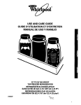
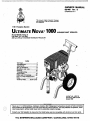
1 HP, Portable, Electric
. .
LTIMATE
AIRLESS PAINT SPRAYER
Model W,Series A
Less hdse,.gun. and filter
SzW psi (210 bad MAXIMUM WORKING PRESSURE
Index
.........................
.......................
.........................
..................
.............
.............................
..................
.......................
..........
................................
.........
.Warnings...
.2
Avertissarnent
4
Advertencih
.6
Set UptOperation
8
Shutdown and Care.;
9
Rushing
10
Tmubleshooting
11
Repair index
.lS
Parts Lists 8 Drawings
32
-How To Order Replacement
Parts
.37
Technical Data
Back Cover
PATENT NO. 4,323,741
PATENTED 1984,Canada
Brevete 1985
_.*.
.I ,, . ,:
. . ......
i
-
,:.
...A
Consult your fluid suppliers to ensure that the fluids being used are compatible with aluminum and zinc
parts.
nerd Safe
equlpment%nerates very high fluid pressure. Sprayfrom
thegun,leaksorrupturedcomponents
can inject fluid
through your skin and into your body and cause extremely
serious bodily injury,including the need for amputation. Also,
fluid injectedorsplashed
into the eyes can cause'serious
damage.
%IS
NEVER poim the spray gun at anyone or at any paq of the
body. NEVER put hand or fingers over the spray tip. NEVER
try to "blow back" paint; this is NOT an air spray system.
ALWAYS have the tip guard in place.on thespray gun when
spraying.
ALWAYS follow the Pressure Relief Procedure, below,
beforecleaning or removing the spray tip orservicingany
system equipment.
N N E R try to stop or deflect leaks with your hand or body.
Be sureaquipmentsafetydevicesareoperatingproperly
ra G n 8af
B
sJe JI gun s % * E 2 Z a r e
operating prop& before
each use. Do not remove or modifv anv Dan of the wn: this
can cause a malfunction and result'in &Nous bodilykju.ry.
Safety Latch
'Whenever you stop spraying, even for a moment, always set
the gun safety latch in the closed or "safe" position. making
the gun inoperative. Failureto set the safety latch can resultin
accidental triggering of the gun.
Diffuser'
T e gun diffuser breaks up spray and reduces
the risk of injechon when the tip is not installed. Check diffuser operation
regularly.Followthe
Pressure Relief Procedure, below,
then remove the spray tip. Aim the gun into a metalpail,
holding the gun firmly to the pail. Using the lowest possible
pmsure. trigger the gun. If the fluid emittedis not diffused into an irregular stream, replace the diffuser immediately.
np
i Guard.
ALWAYS have the tip guard in place~onthe spray gun while
spraying. The tip guard alerts you to the injection hazard and
helps prevent accidentally placing your fingers or anypan of
your body dose to the spray tip.
before each use.
edi!
I rmtmetnt
?
anyT Bamears to Denetrate vour skin. aet
UI
a
Ti
Safe81
e&&
cautio when cleaning or changing spray tips. If
the spray tip clogs while spraying, engage thegun safety latch
immediately.ALWAYS follow the Pressure Relief Procedure and then remove the spray tip to clean it.
NEVER wipe off build-up around the spraytip until pressure is
fully relieved and the gun
latch is engaged.
sa+ty
e thegun safetylatch. (51 Hold
prensura. (61 Engage the gun
If
YOU suspect that thespray tip or hose is completely dogged, or that pressure has not been fully relievedafter following the
Steps above. VERY SLOWLY loosenthe tip guard retainingnut or hose end coupling and relieve pressure gradually,
then loosen
completely. N o w dear the tip or hose.
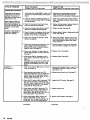
pi
ENGAGESAFETY
TURN SWITCH TO OFF
UMPLUG CORD
DISENGAGE SAFEW
AND TRIGGER GUN;
ENGAGE SAFEW A G A I ~ ~
OPEN DRAIN VALVE
.
.
GEtPed $Pf&Y
.
.
.
.
,
Static electricity is created by the high velocity flow of fluid
through the pump and hose. If every partof the spray equipment is not properly grounded, sparking m y occur, and the
systemmaybecomehazardous.Sparkingmayalsooccur
when plugging in or unplugging a power supply cord. Sparks
can ignite fumes from solvents end the fluid being sprayed,
dust panicles and other flammable wbstances;whether you
are spraying indoors or outdoors, and.can cause a fire or explosionandseriousbodily
injury and property damage.
Always plug the sprayer inM an outlet at leest 20 feet I6 ml
away from the sprayer and the spray area. Do not plug in or
is
unplug any powersupply cords in the spray area when there
any chance of igniting fumes still in the air.
Any misuse of the spray equipment or accessories, such
as
overpressurizing, modifying parts, using incompatible
chemicals end fluids, or using
worn or
damaged
parts,
can
cause them to rupture and result in injection or other serious
bodily
injury,
fire.
explosion
property
or damage.
NEVER alter or modify any part of this equipment; doing so
could cause it to malfunction.
CHECK all spray equipment regularly and repair or replace
worn or damaged parts immediately.
R e a d and follow the fluid and solvent manufacturer's literature
regarding the use of protective clothing and equipment.
$WEm
If you experience any static sparking or even a slight shock
while using this equipment, STOP SPRAYING IMMEDIATELY. Check the entire system for positive grounding. Do
not us8 the system again until the problem has been identified
and corrected.
h@SSMU@
Thb sprayercandevelop
3aW psi (210 b8rJ MAXJMUM
WORKING PR€SSURE Be sure that allspray equipment and
accessoriesarerated
to withstand the maximum working
pressure of this sprayer. DO NOT exceed the maximum workingpressure of anycomponentoraccessoryused
in the
h
system.
Grounding
To reduce the risk of static sparking, groundthe sprayer and
all other spmy equipment used or located in the spray area.
CHECK your local electrical d e for detailed grounding instructiom for your area and type of equipment. BE SURE to
ground all of this spray equipment:
Wuid Compatibility
BE SURE that all fluids and solvents used are chemically compatible with the wetted parts shown in the Technical Data on
the back cover. Always read the fluid and solvent manufacturer's literature before usina
- them in this spraver.
. .
1.
Sprayer: plug the power supply cord, or extension cord,
each equippedwith an undamaged three-orona ulug.into
a properly grounded outlet. Do not use an adapter. extension cords must have three wires and be rated for 15
amps.
2, F/ujdhoses: use onlygrounded hoses with a maximum
of
HighPressurefluid in the hoses can be very d~KIerous.If the
hose develops a leak, split or rupture due to any kindof wear.
damageormisuse, the high pressuresprayemitted from it tan
5M)feet I 1 5 0 ml combinedhoselength to ensuregroundcausaan iniection iniurvorotherseriousbodilviniurvornrc-ing
continuity.Refer
to Hose Grounding Contlnulty.
,~~~
perty dam&
3. Sorev nun: obtainoroundinothrouahconnection
to a
ALL FLUID HOSES MUSTHAVE SPRINGGUARDS1The
pioper6 grounded fhidhe-and spkyer.
4. obieecr being sprayed: according to local code.
springguardshelp protect the hosefrom kinks orbends at or
close to the coupling which can result in hose rupture.
.
5.
TIGHTEN 811 fluid connections murely before each use, High
pressure fluid candislodge a loose coupling or allow high
pressure spray to be emitted from the coupling.
A// so1V&7r Pat7s
when
flushing,
according
to local
code. Use only metalpails,which are conductive. Do not
place the pail ona non-conductivesurface, such as paper
or cardboard, which interrupts the grounding continuity.
NEVER use a damaged hose. Before each use. check the en& To m8intah groundins COntinuiVWhenflushing O r d k V tire hose for cuts, leaks, abrasion, bulging cover,ordamageor
movementof the hose.couplings. If anyoftheseconditionsingpressure,always
hold a metalpart of the gun firmly t o
the side of a grounded metal pail, then trigger the gun.
exist, replace the hose immediately. DO NOT try to recouple
~ ~ M s & ps,fey
high pressure hose or mend it with tape or any other device. A
repaired hose cannot contain the high pressure fluid.
Reduce the risk of injection injury, static sparking, or splashing
HANDLE AND ROUTE HOSES CAREFULLY. D not
~ pull
o~
. by fo!owing .the specific flushing procedure given on page 10
hasas equipment.
to
Do not use fluids o;
which
of
this
manual.
Follow the Pressure Rellef Procedure on
are not compatible with the inner tube andcover of the hose.
' and
the 'pray p
it before flu*in6"
Holda metal
DO NOT expose G~~~ hose
temperinures above 1m-F
pa*of thegunfirmly to the side of a m-1 pail anduse the
lowest possible fluid pressure during flustiing.
(82°C) or below - 4 O O F I4!'C).
Hose G ~ ~ n d i n
Continuity
g
.
... ., ..i
....
.
. I.
..:
~~~~~~
Proper hose grounding continuity is essential to maintaining a
groundedspraysystem. Checktheelectricalresistanceof your
air and fluid hoses at e
l ast once a week. If your hose does not
have a tag on it which specifiesthemaximumelectrical
resiaence, contact the hose supplier or manufacturer for the
mau'rnum resistance limits. Use a resistance meter in the appropriate range for your hose to check the resistance. I f the
resistanceexceeds the recommendedlimits,replace
it immediately. An ungroundedor poorly groundedhose can make
yoursystemhazardous;Alsoread
FIRE OR EXPLOSION
HAZARD.
~
.
PARTS HAZARD
Moving pans can pincii or amputate. your fingers or other
body parts. KEEPCLEAR of moving parts when starting or
operating the sprayer.Unplug the sprayer,and follow .the
Pressure Relief Procedure on page 2 to prevent it from starting accidentally.
.
IMPORTANT
United States Government safety standards
have been adopted under
the Occupational Safety and HealthAct. Thee standards-par.
ticutariy the General Standards, Part 1910, and the Construction Standards, Part 1926-should be consulted.
Coutsignes g6n6ralm de securite
Cet appareii produit un fluida B trh haute pression. LB fluide
pulv4risti parle pistoiet ou ie fluide sous pression pmvenant de
fuiies ou de ruptures peut
p B n h r sous ia peau ou
B I'intBrieur
du corps et entraher des blessurest d s graves, voir mBme une
amputation. MCma sansW e sous pression. ie fluide Bclaboussant ou entrant dans. les yauxpautaussientrainerdes
blessures graves.
NE JAMAIS pointer ie pistoiet vars quelqu'un ou vers une partie quelconque du corps. NE JAMAIS menre ia main ou les
doigts sur I'ajutage du pulvdrisateur. NE JAMAIS essayar de
"refouiar" ia peinture. Cet appareil Nest PAS un compresseur
meumatique.
TOUJOURS garder la protection da I'ajutage en piace sur le
pistolat pendant la puivbrisation.
TOUJOURS observer la March B Suivre pour DBtendre la
Pression donnba plus loin. .avant de nettoyer ou d'aniaver
I'ajutage du puivdrisataur, ou d'effactuer un travail quaiconque sur una partie de I'appareil.
NE JAMAIS essayer d'arrCtar ou de dbvier les fuites avec la
main ou ie corps.
Avant chaque utilisation, bian s'assurer que ies dispositifs de
sBcuritB fonctionnent correctement.
Boins ~ m B d i c ~ X
En cas de pbnbtratlon de fluide sous la peau:
DEMANDER IMMEDIATEMAENIT DES SQIMS
MEDICAUX D'URQERICE.
NE PAS memm c m BLESSURE
~
COW"
U M E SIMPLE CQUPURE.
Dire axacternent au medecin qual typeae iiquida a Bt6 inject&
Dispositifs de sbcurit6 du pistolet
Avant chaque utiiisation, bien s'assure que tous ies dispositifs
de &curit6 du pistoietfonctionnent corractament:Nepas
enlevar ni modifier une partia quelconque du pistoiet: cecirisquerait
d'antrainer
un
mauvais
fonctionnement et des
blessures graves:
Verrou de sdcuritd
A chaque fois que I'on s'arr6ta de puhrdriser, mCme s'il s'agit
d'un court instant, toujours mettre le verrou de skuritb du
pistolet sur la position "fermbe" ou "sBcurit6" l"safe"1 pour
empschar ie pistolat de fonctionnar. Si la varrou deSeCuritB
n'est pas rnis, le pistolat peut se dkiencher accidanteiiement.
Diffuser
Le diffusaur du pistoletseti B diviser le jet et B r&uire les risquesd'injectionaccidantellequandI'ajutagen'estpasen
place. VBrifier le fonctionnament du diffuseur r6guiihramant.
Pour cette vBrification, dhtendre la pression an observant ia
Marche B Suivre pour DBtendre la Pression donn6e plus
loin puis enlever I'ajutage du pulvBrisateur. Pointerie pistolet
+ns un seau en m h i , en le maintenant fermement wntre le
seau. Puis, en utiiisant ia pression la plus faible possible, appuyer sur la gachette du pistolet. Si le fluida projet4n'estpas
diffuse sous forme de jet irrdguiier. remplacer immediatement
le diffusaur.
Rotection de I'ajutage
TOUJOURS maintenir laprotectionde I'ajutage an place surle
pistolet du pulvbrisateur pendant la puldrisation. La protection de I'ajutage attire I'attention sur ias risques d'injection et
contribue B Bviter que las doigts ou une partie quelconque du
B proKimit6immediatede
corpsnepasseaccidenteilement
I'ajutage du pulv6risateur.
bmsiqnes de a6curit6 concwnmt 1'@,4tagB
du
@Mk6PISs'WN
Faire extr&nemant attention B I'occasion du nettoyage ou du
rempiacement des ajutages du pulv6risateur:
Si I'ajutage se
bouchependant ia pulv6risation. mettre imrn4diaternant ie
verrou de sBcurit6 du pistolat. TOUJOURS
bian Observer la
Marche B Suivre pour DBtendre la Pression puis enlever
I'ajutage du pulvdrisateur pour ie nettoyer.
NE JAMAIS assuyer ce qui s'est accumulh autour de I'ajutage
j u pulvbrisateur avant que la pression ne soit completement
tombee et qua le vermu de&curite du pistolat nesoit engag6.
ies blessures-par injection de fluide ou cell@ causeeS d'kla
par boussant
ou par 6lectrocytion,toujoun bien observer cena marche
B suNre B chala vdrification oude la r6paration d'unep i k a de I'appareil de puivbrisaemplacement des ajutageset d'una manihre gBnBrale B chaque an&. 11
nterrupteur Marche-Arrit sur ARRET ("OFF"). 31 DBbrancher le cordon
pistolet. 51 En maintenant une partie metalliqua du pistolet fermement apr le gachette du pistoiet pour iibBrer la pression. 6) Engager le verrou de
prenant Soin d'avoir un recipient prdt B r6cup6rer ie liquide. 81 Laisser la
ur soit de nouveau pr8t B &re utilis6.
Sil'onsoupconneque
menr Jib&e apr& emir
I'ajutage ou ie raccord d
3
4.5.6
7
R!SWfES EN CAS DE ~ A U ~ ~ UUULUSAUOON
n $ E
DU MAUERjEk
Cmsignes g6n6uales $0 sQcuritpB
. .
. .
Puessi n
PRESSION MAXIMUM DE
Toute utiiisation,anormale de I'appareil de pulvBrisation ou des Ce pulvfrisateur peut produire une
TRAVAIL 210 bar f3cX7V Ib/po.2). Sassurerque tous les
aaessoires domrne, per example, ia mise sous une pression
excessive.Ies modifications de pieces, I'utilisation de produits
Bl6ments du Pulv6risateUr et ses accessoires sont concus pour
chimiqum et dematieresincompatibles
et I'utilisation de
rbister B la pressionmaximum detravail dece pulvbrisateur.
NE PAS d6passer la pression maximum de travail d'aucun dss
pi&
udes ou abim6es peut causer des dBg8ts
B I'appareil ou
46ments ou accewires utili& avec cet appareil.
des ruptures de p i k et entrainer une injection deliquide ou
bm slet
c A i ~ n i 88 cou
d'autres
blessures
drieuses, un incendie,
une
explosion
ou
d'autrm d6gAts.
Tous que
!'A&URER
BlEN
utilishs
corpf
solvants
des
les
Parties mouillbas insont
chimiquement
compatibles
avec
NE JAMAIS alt6rer ou mod#ier une piece de cet appareil; ceci
diqubes dans ies"Donn6es techniques", au dos de la couverrisquerait d'enuainerson mauvais fonctionnement.
ture. Toujours lire soigneusement18s documents et brochures
VERIFIER r6gulihrement tout I'appareil de pulv6risation et ses
du fabricant des fluides a
utilisb avant de Sfen servir
6quipements et r6parer ou remplacer
immddiatement
Ies
dans
pulvBrisateur,
,
p i h s us& ou abim6es.
~~
fes
~
M E W R E S DE SEWROUE CONCERNANU LE$ TUYAUX FBEXIBLES
Le fluide B hautepressioncirculantdans les tuyauxpeut&repar
tout autrem'oyen.
trk dmgereux. En cas defuite sur le tuyau, mame minuscule,
fluide sous pression.
de fissure,
dbchirure
rupture
ou
B la suiteI'usure,
de
d6gats
de
MANIPULER LES TUYAUX
ET
de fluide haute
. CHOISIR solGNEUsEMENT LEUR
Ne pas d6placer
ou
d'une
rnauvaise
utilisation, les projections
PreFSion qui en proviennentpauvententrainerdesbl-urle fluide en rent sur le
Ne wsutiliser
defluides ou de
graves
par
pendtratbn sous la pew ou par contactt.ainSi
que
qui ne
pas compatibles aYBC I~enVeloppe~in.
des d 6 g h mat6riels.
!
tBrieure ou endrieure du tuyau. NE PAS expcser
le tuyau B
TOUS LES TUYAUX FLEXIBLES 'DOIWENT AVOlR DES
destempdraturessuphrieures B 82°C(169°F)ouinfbrieures B
RESSORTS SPIRALE DE PROTECTIONI Lesspiralesde
4 ' C (4°F).
protection contniuent B biter la formation de
pliures,
de
GonainuiitedQ,la,
,a,ter dss vu 8ux
boucles ou de nosuds sur18s tuyaux qui pourraient entrainerla
Une benne cont,nu# Je la
wrre
tuyeux
rupture du tuyau B I'endroitduraccordou B sonvoisinag6.essentiellepourmaintenir
la mise B laterredeI'ensamblede
SERRERFERMEMENTtousIes racmrds avantchaqueutilisz-vaporisation.VBrifiez
ia rkistance 6iectrique de vos Waux h
fluides et B air, a.u moins une fois par semaine. Si votre tuyau
tion. Le fluide souspression peutfairesauterunraccord
ne comporte pes d'etiquene qui prBcise ia rbistance Blectridesserr6 ou produire un jet B haute pression s'6chappant par
le
prenez
maximum,
que raccord.
contact
le
avec foumimur
tuyaux
de
ou la fabricant pour avoir l e s limites de Aistance maximum.
NE JAMA~Sutiliser un tuvau endommagb. Avant c h a w
Utiliser un metre de r6sistence de lagammeappropride pour
utiliiation, verifierentihrementchaquetuyaupourdeceler
les
~ t r e
tuyau et v6rifiaz
dshnce,
si ceile-G dBpasse ies
limiteS
recornmand6es, remplacez
letuyau immwiaternent.
coupur-. fuitm. abrasions.boursouflur=
de renveloppd ou
route a m dBt6riorationoujeudesraccords.
Si I'on constate
Un tuyau s a nFisc
~ a terre ou avec une
al twre incor.
rune de cas detBriorations, iJfaut
remplacer le tuvau
imreae peut
dm ~sques
pour VOtre systeme. ,jsez
mbdiatement. NEPASessayerderefaire
le raccordd'un tuyau
LES RISQUES D,INCENDIE ou DzmPLOSION ci-dwus,
haute pressionni de rbparer le tuyau avec du
Nban adhbif ou
JTa
'
RISQUES ~
1 OU WEXPLO$lON
~
~
De I'6lectricitB statique est produite par le passage du f1uide.B
grande vitesse dansla pompe et dans ies tuyaux. Si toutes Ies
pikes de I'appamil de pulv6risation ne sont pas convenable
ment reli6es B la masse ou a la terre, des Mrncelles peuvent se
produire et I'appareilrisque &&re dangereux.Des hinceiles
Peuvent balement se
Produire iI'occasion
du
branchemem
ou du dbbranchemant du cordon d'alimentation. Les Btincelies
sont suffisantes pour allumer les
vapeun de wlvants et le
fluidepulvdris6, les finesparticulesdepoussihreainsique
d'autres substances inflammables, quend on pulv6rise B I'int6rieur ou B I'extBrieur. et elles oeuvent causer un incendie ou
une explosion. ainsi que des blessures g r a ~ ketdes db@ts
se
matbriels. Toujoun brencher le pulvdrisateur dans une prise
trouvant B au moins6 m ( 2 0 piedsl de I'appareil et de I'endroit
oh se fait la pulv6risation. Ne pas brancher ou d6brancher un
cordon d'alimentation quei qu'il soit dans la zone oh se fait la
pulv6risation quand il y a le molndre risque que des vapeurs
encore prbsentes dans I'air prennent feu.
S'il se produit des 6tincelles d'6lectricitB statique, ou si vous
ressentez la moindre dbcharge, ARRETR IMMEDIATEMENT
LA PULVERISATION. VBrifiez aue le s W h e entier est bien
mis B la terre. Ne vous servezpai du s y a i h e avant quele probldme soit identifie et corrigd.
fiWh
... ..
.. . .
~.
la tWPe QU & la
lllaS88
Pour r6duire iesrkques de production d'Btincelles d'BlectricitB
statique, le pulvbrisateur eitous les 6quipements utilids ou se
tmuvent dans la zone de pulvbrisation doivent &re relis B la
term ou B la masse. Pour connaitre le detail des instructions de
mise B la terre dans la rdgion et le type particulier d'Bquipe
ment, CONSULTER le code oue
ls rdglementations Blectriques
locales. S'ASSURER que tous Ies 6quipements de pulvbrisation suivants sont bien rell6s B la terre:
le cordond'alimentation
ou la
1.Pulvdrisateur:Brancher
rallonge qui doivent &re BquipBs d'une prise B 3 fiches en bon
&at, .dam une prise de murant convenablement mise B la
terre. Ne pasutiliser d'adaptateur. Toutesles rallonges doivent
avoir 3 fils et &re pr6vues pour 15 amp8res.
~
~
&
~
~
2. Tuyaux flexibles: Afin d'assurer la continuit6 de la mise B la
B la terre
term, n'utiliser que des tuyaux comportant une mise
et
avant
une
longueur
maximum
cornbin&
de
1% m
(1500pieds).Sereporter6galementauparagraphs
"Continuit6 du circuit de mlse B la terre des tuyaux".
3. mstolet: ~
la
~
&~laterre l en leraccordant
i
~
un~
tuvau fle~ble et +un
, pulv6risateurdeja convena~mentreli&
B ia terre.
.
.
4. Objets, mat.4rid ou surfacesrecevant la puldrisation:
observer le code ou les dalementations locales.
5. Touslessaaux de solvants utilis& pour le rincage: observer
le code ou ies rbglemenmtions locales.
N'uMser que desseaux
mdtalliques conducteurs de I'Blectricite.Ne pas mettre leseau
sur une surface non conductrice comme.sur du papier ou du
carton car cela interrompreit ia continuit6 le le mise la terre.
6. Pour conserver la continuit.4 dela mise B la terre quand on
rince le mat6riaI ou quand on lib* la pression, toujours
maintenir une partle metaliiquepistoiet
du
fermement appuy6e
contre le cbt4 d'un seau en m.4td puis appuyer sur la d6tente
du pisfolet.
Rnswm DUS AUX PECES
EM
~~~~~~~~~
Les pieces en mouvement peuvent
pincer ou couper 1 8 5 doi
ou d'autres parties du corps.SE TENlR A L'ECART des pieces
la miseen route et la marchedu
enmouvamentpendant
pulv6risateur. Pour Bviter un d6marrage accidentel, ,debrancher
et IibBrer la pression avant d'effectuer des
. le pulvBrisateur
.
arations.
MPORTAWT
Lees nomes de s6curitB du Gouvernement des Ems-Unis ont
&B adoptBes en vertu de la Loi sur la SBcurit6 et l a Sam6 au
Travail. Ces normes et, particulidrement, ia Section 1910 des
Normes GBn6rales ainsi que la Section 1926 des Normes de la
Construction, doivent atre consult&.
Fun43E5
E
~
Seeguridad general
Este equipogeneraunfluidoaunapresi6nmuy
alta. 0
Aparatos de seiuridad de r
Ia pi5tOl~3pulverized&
Asegurar que todos i o s aparatos protectores de la pistola
estsn funcionandobienantesdecadauso.
No scar ni
rociado de la pistola. 10s escapes de fluido o roturas de los
wmponentes pueden inyectar fluido en la piel y el cuerpo y
causar lesiones earemadamente graves, incluyendo a veces
la
necesidad de amputaci6n. Tambih. el fluidoinyectado o
salpicado en 10s ojos puede causar graves daflos.
NUNCAapuntarlapistolahaciaalguien
o algunapartedel
cuerpo. NUNCA colocar la manoo 10s dedos encima dela bquilla. NUNCA tratar de "hacer retornar la pintura"; este NO
es un sistema de rociado de aire.
SIEMPRE tenercolocado el protectordelaboquillaenla
pistola mientras se est6 pulverizando.
SlEMPREseguir elprocedimiento dedescarga de presi6n.
dado m& abjo. antes de limpiar o Sacar la boquilla o de dar
servicio a cualiquier equipo del sistema.
o ei
NUNCA tratar de parar0 desviar los'escapes con la mano
cuerpo.
10s aparatosdeseguridaddel.equip0
Asegurarquetodos
e d n funcionando bien antes de cada uso.
Cada vez que se deje de pulverizar, aunquesa8 por un breve
momento.siemprecolocarel
p e s t " deseguridaden
la
posici6n"cerrada". Io quedejala pistola inoperante. El no
hacedo puede llevar al disparo imprevisto de la pistola.
Difusor
8 difusor de la pistola dispersa el chorro pulverizado
y reduce
el riesgo de inyeccidn cuando no est6 instaiada la boquilla.
Revisar con reguiaridade1 funcionamiento del difusor. Seguir
el procedimiento de descaigade presi6n. dado rnhsabajo.
y despub sacarlaboquilla.Apuntarlapistola
a unbalde
mat6lico.sosteni4ndolabien firm contra 61. Utilizando ia
presi6n m6s bajoposible,disparar
ia pistola. Si el fluido
emitido no sale disperso en un chorro irregular, reemplazarde
inmediato el difusor.
Tratamiento mddico
Rotactor de la boquilla
Si pareciera que un.poco de fluido.penar6 la piel, conseguir
TRATAMllENTO MEDICO DE UROENCIA DE
INMEDIATO.
NO TRATAR LA HERIDA @DM0UPJ SIMPLE CORTE.
Deciralmedicoexactamentecua
fluido fue.
modificar ninauna oieza de la oistola
Dues oodrla causar el
malfuncionamlento be la mismacon ias consiguientes [miones
personalas.
Pestillo de seguridad
SIEMPREtener e1 protector de laboquillacolocado
en la
pistola mientras se est6 pulvenzando. Este protector llama ia
atenci6n contra el peiigro de inyecci6n y ayuda a prevenir la
colocaci6n accidental de 10s dedos o cualquier otra parte del
cuerpo cerca de la boquilla.
Sagupidad de la bcqullla pulverizadcra
Tenermuchocuidado al limpiar o cambiarlasboquillas. Si
llegara a obstruirse mientras est6 pulverizando; enganchar el
pestiilo de la pistola de inmediato. SIEMPRE seguir
el piocedimiento de descarga de presl6n y despub Sacar la boquilla para limpiarla.
NUNCA limpiar la acumuiacibn de pintura alrededor de la boquiilaantes i13 quesehayadescargado
por cornpleto la
..esidn y el pmillo est6 enganchado.
Procedimiento dedescarga depresi6n
o lesiones causadaspor piezas en movimiento o
Para reducir el riesgo desufrir graves iesiones corporales, incluyendo inyecci6n
choque el6ctriw, Siempreseguir esteprocadimiento al apagarla T6quina pulverizadora,
al revisar o dar servicio a cualquier parte
del sistema de pulverizaci6n.al instalar, limpiar o cambiar Ias boquillas, y cada vez que se deja de pulverizar. 11) Enganchar e1
(21 Mover e1 intenuptor elbctrico ION/OFF) a la posicibn OFF (apagadol. I31 Desenchufar el cord6n
Pestillodelapistola.
elhrico. (4) Desenganchar el pesu'llo de la pistola. 15) Sujetar una parte m d l i c a de la pistola bien firme contra un balde de
161 Enganchar e1 perstilio de lapistola. 17) Abrir la vhlvula de drenaje
y tener
metal, y disparar la pistola para descargar la presi6n.
list0 un reclipiente para recibir la pintura.
18) Dejarlav6lvuladedrenajeabiertahastaque
se est6nuevamente iisto para
pulverizar.
SiSe sospacha que la boquila o la mnguera estd
despuhs de haber seguidoel procedimiento
qutlla o acoplamiento de la pun- de la man
despajar la boquilla o la manguera.
"ERRUPTOR
.. . .. .
,..
. . . :. .,.
..
..~.
'
2
.~.
PELhGRO POR MAL U S 0 DEL EQUPO
PBBGW6 DE 8NCENDlO 8 EXPLO$lOM
segws~dedgpwasal
El flub a alta velocidad del Ruido al .pasar por la bomba y
Cualquler mal us0 de( equipo pulverizadoro 10s accesorios. tal
como ~brepresurizaci6n. modificaci6nde piezb, UM de
matenales y pmductos quimicos incompatibles, o utiliuaci6n
depiezasdaiiadas o desgastadas,puedehacenqueserompan
y causenlainyecci6ndefluido
u otraslesionescorporales
graves, incendio, explosi6n o daiion a la propiedad.
NUNCA alterar o modficar ninguna pieza de este equipo; el
hacerlo podria causar una averia.
REVISAR con regularidad el equipo pulverizador y reparar o
reemplazar de inmediato las piezas daiiadas o desgastadas.
PwiOn del sietema
Esta pulverizadora puede desarmllar 210 barlas WM psi) de
PRESION DE TRABAJOMAXIMA.Asegurarquetodoel
equip0 pulverizadory sus accesorios tienen la capacidad para
aguantar ia presi6n maxima de trabajo de esta pulverizadora.
NOexcederla presi6n maximade trabajodeningrlncomponente o acmorio de m e sistema.
Cornpatibilldad de Fluid0
ASEGURARque todos 10s fluidos y saiventesusadosson
ls piezas mojadas ilustradas
quimicamente compatibles con a
en.la hoja de datos tbcnicos en la contratapa. Siempre lee las
y sulvente a n t d de
instruccionesdelfabricantedelfiuido
usarlos m esta pulverizadora.
Pu@sta61 tierm
Para reducir el riesgo de chispas esthticas. conectar a tierra la
pulverizadora y todo el otro equipo de pulverizar que se useo
se encuentre en el iugar que se va a rociar. CONSULTAR el
c6digo elbctrico de la localidad
para las instrucciones sobre
IBS
conexiones a tierra exigidas para la zona
y tip0 de equipo.
SEGUR!DAD EN EL
DE BAS ~
~
~ de
Utodo
~
ASEGURAR
conectar
a ~
tierra
este
equipo
El fluido que pasa a aka presidn por 18s mangueras puede ser
pulverizador:
muy peligroso. Si en la manguera se desarrolla un escape pe1. Pulverizadora: enchufar el cord6n elbctrico, o cable exteno rajaduradebidoacualquier
tip0 de
queiio.unarotura
desgaste. daiio o maitrato, el chorro a aka presi6n emitido por sor, cada uno con un enchuf de tres patas en buen estado, a
un tomacorriente con puesta a tierra apropiado. No usar un
a
l
ipuede causar una lesi6n por inyecci6n
u otras lesions coradaptador. Totos 10s cables extensores tienen que tener tres
porales graves o deiion a la propiedad.
hilos y una capacidad de 15 amperios.
lTODAS U S MAMGUERAS PARA FLUIDOSTIENEN
QUE TENER GUARDAS DE RESORTEI Estas protegen las , 2. Mangueraspara fluidos: usarsolamentemanguerascon
puesta
tierra
a de
una
longitud combinada
de
150 m
mangueras contra dobleces0 retoreeduras en10s acopiamien( 5 0 0 pies), para asegurar buena continuidada tierra. Referirse
en roturas de le
tos o cerca de ellos, 10s que podrian traducirse
tambiknalphrrafosobre
continuidad a tierrade.la
manguera.
manguera.
Antes de usarlas, APRETAR bien firmes todas las conexiones.
3. pistola:hacerlapuesta
a ti.erraconecthndola a una
El fluido a alta presi6n puede desalojarun acoplamiento sueito
manguera de fluido y puiverizadora bien conectadas a tiena.
o dejar que por bt escape un chorro a aka presi6n.
4. Objeto que $e estd rociando: de conformidad con el cddigo
NUNCAusarunamangueraque
e& daflada.Siempre.
local.
revisarla en busca de cortaduras, escapes, abrasih, cubierta
abultada, o acoplamientos sueltoso datiados. Si llegara a en5. Todos 10s baldes de solvente usados durante el lavado, de
contrarse cualquiera de m a s condiciones, reemplazar de inconformided con el c6digo local. Usar solamente beldes. de
mediato la manguera. NO intentar reacoplar una manguera de
meta4 que,sesnconductivos. No coiocarelbaldeenuna
aha presibn o enmendarla con cinta adhesiva u otro material
o cartbn,queintersuperficienoconductiva,comopapei
similar.Una manguera que ha sido remendada no aguante el
rumpe la continuidad a tierra.
Ruido a aka presi6n.
6. Para mentener la continuidad a tierra duranre el lavado o
CUIDADOSAMENTE
LAS
MANEJAR Y PASAR
descarga de presidn, siempre apoyar una parte metelica de la
MANGUERAS.Notirardelasmanguerasparamoverel
pistoiabien firme contra eicostadodelbeldedemetal,
equipo. No usar fluidos o solventes qua Sean incompatibles
despuk apretar el gatillo.
con ei tubo interno y la cubierta dela manguera. NO exponer
S y q l d a q .durante e l Ba\rgd~
lasmanguerasatemperaturassobre
82°C (180OF) o bajo
R uclr el rlesgo de lesiones por inyeccibn, chispas elbctricas
4 ' C (-4O'F).
o salpicaduras.
siguiendo
procedimiento
el
de
lavado
especffico dado en la phgina10 de este manual. Seguir81 proContinuidad de[ EIPCM~FO
ola.puesta 8 tierpa de la
cedlmlento dedescarga de prasi6nen ia phgina 6, v quitar
manguara
la boquilla rociadora antes
de l a w . Apoyar una pane metblica
La continuidad del circuit0 de puesta a tierra apropiado
es
de la pistola bien firme contra ei costado
de un balde de metal
esencial
para
mantener
conectado
tierra
a sistema
el
y usar la presi6n mhs baja posible de fluido durante el !avado.
pulverizador. Es indispensablerevisarlaresistencia elktrica
y de fluidopar lo menos una
maxima de Ias mangueras de aire
vsz a la semana. Si la manguera no tiene una etiqueta en la
cual se especifica le resistencia eltktrica maxima, ponerse en
Las piezas en mowmiento pueden pincharo amputar dedosu
contact0 con el proveedor
o fabricante de la manguera para la otraspartesdelcuerpo.MANTENERSEALEJADOdelas
informaci6n sobre10s limites de resistencia. Usar un metro de
piezas en movimiento durante el arranque o funcionamiento
resistencia en l a gama apropiada para comprobar la resistende la pulverizadora. Desenchufar la pulverizadora y descargar
cia; si excede 10s limites recomandados, reemplazarla de inla presi6n antes de revisarlao darle servicio, para impedir que
mediato. Es muy arriesgado tener una manguera sin puesta
a
arranque inesperadamente.
tierra o'con la puesta a tierra en malas condiciones. Leer tamIMPORTANT
bi6n la informaci6n sobre RIESGO DE INCENDIO
0 EXPLOSe
han
adoptado
las
normas
de seguridad del gobierno de
10s
SION. d s amba.
Estados Unidos de Noneambrica bajo el Acta de Seguridad y
SaludOcupacionai.Deberhn
consultam estas normas,en
especial Ias Generales, Parte 1910; y las Normas de Construcci6n. Pane 1926.
us0
. . ..
.. :. i
mangueracreaelectricidadest6tica.Sitodas
18s panes del
equipopulverizador no tienenbuena tierra.puedenocurrir
chispas, convirtiendo ai sistema en algo peligmso. Tambibn,
pueden producirse chispas a1 enchufar o desenchufar el cord6n el6ctrico. €staschispas pueden inflamar los vapores de
10s solventes y ei chorro de fluido puiverizado, panicuies de
polvo y otras sustancias infiamabies, sea al aire libre o bajo
techo; Io que podria causar una explosidn
o incandio y graves
Iesiones corporales y dafios a la propiedad. Enchufar siempre
la pulverizadora aun tomacorriente quese encuentre a por io
menos 6 m ( 2 0 pies) de la mhquina y dd A r e a que 88 va a
rociar. No enchufaro desenchufar ningrln cord611 elbctrico en
ia
ellugardondeseest6rociandocuandotodaviaexista
posibilidad de que queden vapor- inflamables en el aire.
Si se observa alguna chispa esthtica, o se siente el mas leve
choque
elbctrico.
APAGAR DE INMEDIATO
LA
PULVERIZADORA. Revisar todo el sistema en busca de conexi6n a tierra positiva. No usar nuevamente el sistema hasta
haber ubicado y corregido el problema.
~
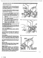
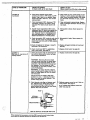
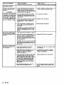
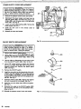
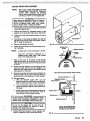
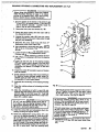
Connect Hose end.Gun
Connect at least 50 . f t (15 m) hose to the fluid outlet of
the pressure control. See Fig 1. Connect a spray gun to
of the hose. Don't use thread sealant, and
the other end
don't install the spray tip yet!
For two gun hookup, remove the plastic cap plugfrom
ball valve and connect
an accessory
the secondary hose
hose and spray gun. See Fig 1.
CAUTION
To avoid damaging the pressure control, which
may result in poor equipment performance and
component damage, follow these precautions:
1. Always use at least 50 f-t (15 m) of nylon
spray hose.
2. Never use ewire braid hose asit is too rigid to
act as a pulsation dampener.
3: Never install any shutoff device beVe6n the
fluid outlet of the pressure control and the
first 50 ft (15 m) of spray hose.
4. Always use the main fluid outlet for one-gun
operation. Never plug this outlet.
II
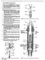
Fill Packing NutlWdt Cup
Pour throat seal liquid, supplied with the sprayer, into
the packing nut/wet-cup until it is 1 / 3 full. Keep the
wet-cup filled'to help protect and prolong thelife of the
pump throat packings. See Fig 2.
Check Electrical Service
Be sure theelectrical service is 120 V, 60 HzAc,
15 amp (minimum) and that.the outlet you use is properly grounded.
SECONDARY
Use an extension cordwhich has3 wires of minimum 12
gaugesize, rated for 15 Amps, andamaximum
of
1 5 0 h (45 m) long. Longer lengths may affect sprayer
performance.
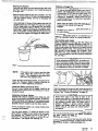
Plug In Sprayer
Be surethe ON/OFFswitch is OFF. Plug the power supply cordinto a grounded electricaloutlet that is at least
20 ft (6 rn) away from the spray area to reduce the
chance of a spark igniting the spray vapors. See Fig 3.
Fig 2
Do not removethe thirdprong of the power supplycord
plug, which is the grounding prong,and do not use an
adapter.
Flush the Pump
flush the pump to remove h e No. 10 motor oil which
was l e f t in to protect pump parts after factory testing.
Refar to page 10 for WHEN and HOW to flush.
Prepare the Paint
Prepare the paint according. to themanufacturer's
that mayhave
recommendations.Removeanyskin
formed,and stir the paint to dissolve hard pigments.
Strain the paint through a finenylon
mesh
bag
[available at most paint dealers) to remove particlesthat
could clog the spray tip. This is probably the most important step toward trouble-free spray painting.
Fig 3
..;.: .:,, :: 1,
. ..... ..........,,
.;.. .. ...
.
,
,
.
____
._....
-..,,
~~~~~
~ , , ~ ,..,
..~.
,,...~,,,
...*i,~~,"~-,.L.
..... ._. .ll.,..,) . .
,_","-mid
......................................................
".LX&&
~~
~
~
.
~
~
~
'.~.
. ..-.-~
-
~
1_..L
~
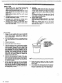
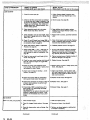
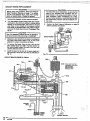
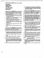
Priming the Sprayer
Cleaning a Clogged Tip
Close the main drain
valve and the secondary ball valve.
See Fig 2. Plug in the sprayer. Don't install thespray tip
in the gun yet1
- -.
..
Place the suction tube into the paint container.Turnthe
pressure control knob all the way counterclockwise to
lower
the
pressure setting. See
Fig
3. Disengage
the
gun safety latch.
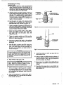
Hold a metal part of the gunfirmly against the sideof a
grounded metal pail, and trigger the gun into the pail.
Hold thetrigger open, turn the sprayer ON,and slowly
increase the pressure setting until the sprayer starts.
Refer to Fig 4. Keep the gun triggered until all air isforced out of the system, andthe paint ROWS freely from the
gun. Release the trigger and engage the safety latch.
Follow the instructions given in your separate gun or
spray tip instruction manual for cleaning a spray tip.
/
.... ... ....._....._.
~
METALTO METL
CONTACT BETWEEN
GUN AND CONTAINER
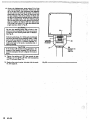
SHUTDOWN AND CARE
Check the packing nut/wet-cup daily. First follow the
Pressure Rellef Procedure Warning on page 2 or 11.
Keep the wet-cup 113 full of throat seal liquid at all
times to help preventfluid buildup on thepiston rod and
prematurepackingwear.Thepacking
nut shouldbe
tight enough to stop leakage, but no tighter. Overtightening maycause binding andexcessivepacking
wear. Use a screwdriver and
light hammer to adjust the
nut. See Fig 5.
en adjusting the packing nut, be careful not to
nick the cylinder threadswhich may beprotruding
above the bearing housing.Nicks to these threads
may strip the threadsin the bearing housing when
the displacement pump is removed or installed.
Fig 4
MOTE:
DO NOT try to "blow back" paint; this is NOT an
If the paint is hard to prime, open the drain
valve. When fluid comes from the valve,
close it. Then disengagethe gun safety latch
and follow the paragraph above.
Check all fluid connections for leaks. If any are found,
on
follow the Pressure Relief Procedure Warnlng
page 2 or 11, before tightening connections,
Install the Spray Tlp and TipGuard
Be sure the gun safety latch is engaged. Install the tip
and tip guard as instructed in the separate gun ortip ivstruction manual.
Adjusting the Spray Pattern
Increase the pressure adjusting knob setting just until
spray from the gun is completely atomized. To avoid
excessive overspray and fogging, and
to decrease tip wear
and extend the lie of the sprayer, always use thelowest
possible pressure needed to get the desired results.
If more coverage is needed, use a larger tip rather than
increasing the pressure.
.~
..i.
....
.~
',?
. ..,... .
:. . . . ,.
:
I
. .:; ,,
'L..s
Test the spray pattern. To adjust the direction of the
spray pattern, engage the gun safety latch and loosen
the
retaining
nut.
Position
the
tip so the groove
is
horizontal for a horizontal pattern or vertical for a vertical pattern. Then tighten the retaining nut.
Fig 5
Flush the sprayer at the end of each work day andfill it
withmineral spirits to help prevent pump corrosion
and
freezing. See "Flushing Guidelines" on page 10.
ious 'sprayer damage.
pints for the final flush,
ave the mineral spirits in
For very shortshutoff periods, leave thesuction tubein
the
paint,
follow the Pressure Relief Procedure
Warning, and clean the spray tip.
Coil the hose and hangit on the hose rack whenstoring
the sprayer, evenfor overnight, to help protect the hose
from kinking, abrasion, coupling.darnage, etc.
:
When to Flush
1. New Sprayer. YournewUltimateNovaTM
lo00
Sprayerwas factow. tested in No. 10 motor oil
which was left in to protect pump parts.
Before using wafer-base palnt, flush with mineral
spirits, followed by soapy water, and then a clean
water flush.
Before uslng oibbase palnt, flushwithmineral
spirits only.
2. Changing Colors. flush with a compatible solvent
such as mineral spirits or water.
3. Changingfrom water-base t o oll-basepaint.
flush with soapy.water, then mineral spirits.
4. Changing from oil-base to water-basepaint.
Flush with mineral spirits, followedby soapy water,
then a aean water flush.
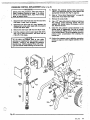
How to Flush
1. Engage the gunsafetylatch,
turn the ON/OFF
switch to OFF, release the gun safety, trigger the
gun to relieve pressure, engagethe gun safety and
open the drain valve.
2. Pour one-half gallon (2 liters)of compatible solvent
into a bare metal pail. Put the suctiolrtube in the
pail.
3. Close the drain valve.
4. Remove the spray tip from the gun.
5. Point the spray gun into a metal waste container
and with a mepl part of the gun firmly touching the
m
e
a
tl container,squeeze
the gun trigger. 'See
Fig 6. T h k procedure helpsawoid stetlc sparking
and splashing. With the gun triggered, turn the
ONIOFF switch to ON and slowly turn the pressure
adjusting knob clockwise lust untll the sprayer
starts. Keep the gun triggered until clean solvent
tha triggerand
comes from thenozzle.Release
engage the gun safety latch.
6. Check all fluid connections for leaks. If any leak,
first turn the ON/OFFswitch to OFF, then open the
drain valve slowly to relievepressure. Now tighten
the connections, start the sprayer, and recheck the
connections for leaks;
7.
from the ho&.bo nG-let thspump.run dry ior
more then 30 seconds to avoid damaging the
pump packingsl Then turn ON/OFF switch to OFF
and engage the gun saftey.
5. Storage.
Water-base paint flush with water, then mineral
spirits and leavethe pump, hose andgun filled with
mineralspirits. Shutoff and unplug the sprayer,
open the drain valve to relieve pressure and leave
open.
Oll-bese paint: flush with mineral spirits. Shutoff
and unplug the sprayer,open the drain valve to
relieve pressure andleave open.
6. Stenup after storage.
Before using water-base paint, flush out mineral
spirits with soapy water andthenacleanwater
Rt
mh
..I"...
When using 011-base paint, flush out the mineral
the
spirits with the material to besprayedand
sprayer is readyto use.
1
fig 6
9.
sprayer
again.
If you flushed with mineralspiritsandaregoing
to
use a water-base paint, flush with soapy water followed by a clean water flush. Then repeat Step 1.
.
. . .. .
.,
.I
. ...
~.
-
~.
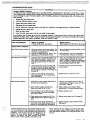
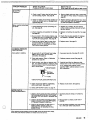
,TROUBLESHOOTING GUIDE
~~~~U~~
...
1.
2.
3.
4.
5.
6.
Engage the gunsafetylatch.
Turn the ONIOFF switchto
OFF.
Unplug the powersupplycord.
Disengagethegunsafetylatch.
Hold a metal part of the gun firmly to the side of a metal pail, and trigger the gun to relieve pressure.
Engagethegunsafetylatch.
8. Leave the drain valve open until you are ready to spray again.
BasicMechanicalProblems
1. Check for fmzenor hadened material in the 1. Thaw'.Plug in sprayerand turn on.Slowi)
setting to see ifmotor
pump (39)and/or pressurecontrolbourdonincreasepressure
tube. Using a screwdriver, carefully try to
stam. If it doesn't, replace the displacemei
rotate fan at back of motor by hand. See
pump packings (see page 26) andlor replac
page 77
pressure
the bare
control box (306)'.
2. Checkdisplacement pumpconnecting rod
2. Push pin into placeandsecure with the
pin 1201. It must be completely pushed into
- springretainer.
connecting md (3)and spring retainer 135)
'
should be firmly in g r m w of connecting rod.
See page 28.
3. Cheok for motor damage. Remove driw
2. Replace motor (1) if fan won't turn.
housing assembly (2). Try to rotate fan by
hand. See uaae 30.
lsicElectricalProblems
1. Checksprayer circuitbreaker 1309'button to 1. Depress circuit breaker button to reset. If
be
sure
it has not popped
up.
ciicuit breaker continues to open, see "Elec
3
pageShort",trical
16.
2. Checkelectricalsupply with volt meter.
Meter
should
read
105 to 125 VAC.
2. Reset building circuit breaker;replace
building fuse. Try another
electrical
outlet.
3. Checkextensioncord
3. Replaceaxtension cord.
4. Ch,ecksprayerpower supply cord (311) for
wlble damage such as broken insulation or
wires.
4. Replacepower supply cord. See page 20.
5. Check motorbrush leads, terminalsand
brushlength.Brushlengthshouldbe
9/16"
minimum on the longest side. Sea page
5. Tightenterminalscrews;
See page
for visibledamage.
Use a volt meter or test lamp at extension
cord outlet to check.
25.
.:; .
. .
. . .. ,. .
.",.
'~~
'Thaw the sprayer if water orwater-basedmaterialhas frozen
in it, duetoexposure
to low temperatures,byplacing
it in a
warm area. Do not try to start the sprayeruntil it has thawed
completely. If the bourdontubewas not damaged by the
freezing. thepumpshould
operate. If materialhardened
(dried) in the
sprayer,
thepumppackings
and/or bare
pressure control must be replaced. See page 23 or 26.
25.
replaw brushes.
W e n replacingthebare presure contml box litem 306).
remove the circuit breaker, ON/OFF switch,bridge.circuit
board and electrical hardware and reinstall these parts in the
bare box.
"
.^..
..
refer to *is colu~
HOTOR WONTOPERATE
Iiagnosing circuit board inIicator lamps. The normal
andition is red lamp on,
$ear lamp on when board
elling pump to run.
1. Check leads from bridae 1 3 0 8 1 to motor to be 1. Replace any loose terminals and crimp to
leads.Besuremaleterminalbladesare
sure they are securelyjastened and properl)I
mated.
straight and firmly connected to mating pa
I
2. Check G1 and 62 connections between cir-
2. Clean circuit board male terminals. Replacl
loose or damaged terminals. Securely reco
nect leads.
3. Check for loose motor brush lead wnnections and terminals. See page 25.
3. Tighten terminal screws. Replace brushes i
leads are damaged. Sea page 25.
4. Check brush length which shouldbe 9/16"
minimum on longestside.Sea page 25.
4. Replace brushes.
cuit board 1121) and bridge 1308) for damagl
or loose terminals.
:allow Pressure Relief Prondure. Remove gun from
lose. Remove pressure cor
rol cover and check for fat
ondition of circuit board
mps.
:ondtion A both lamps On;
lump won't operate and
mor is not running
Sea page 25.
5. Check for broken or misaligned motor brush 5. Replace spring if broken. Realign spring wi
springs. Rolled portion of spring must rest
brush. See page
5.
squarely on top of brush. See page 2
25.
6. Check motor brush& for binding in brush
holders. See page 25.
6. Clean brush hoiders. Remove carbon with
SWall cleaning brush..Align brush lead with
slot in brush holder to assure free vertical
brush movement.
I
7. Check moior armature commutator for burn
7 . Remove motor and have motor shop resurface commutator if possible. See page 31.
spots, gouges and extreme roughness.
Remove motor cover and brush inspenion
plates to check. See page
25.
8. Replace motor. See page 31.
3. Check motor armature for shorts using armature tester (growler) or perform spin test.
See page 17
( 3 0 8 ) by substituting with a
good bridge or performing bridgetest. See
page 18.
CAUTION: Do not perform this check until
armature is determined to be good. A bad
armature will immediately bum out a good
bridge.
I. Check circuit breaker (309)button to be sure
it has not popped up.
3. Replace bridge. See page 21.
!. ChecA sprayer power supply cord (31 1).
?.Replace power supply cord. See page 20.
. Check ON/OFF switch 1 3 ~~~.
M I . Disconnect TP2
I. Replace ON/OFF switch. See page
3. Check bridge
Dndition 8
fh lamps off
I . Depress circuit breaker bunon to reset. If cil
cuit breaker continues to open, see "Electrical Short", 16.
Disconnect TP6 female and TP1 female and
connect volt meter to these leads. Plug in
sprayer. Meter should read 105 to 125 VAC.
Unplug sprayer. Reconnect T
P
.
l
~
~~
~
,
and connect volt meter to TP6 female and
TP2 male. Plug in sprayer and turn on. Meter
should read 105 to 125 VAC. Turin offand
unplug sprayer. Reconnect TPZ.
and connect volt meter to TP6 female and
TP3 female. Plug In sprayer and turn on.
Meter should read 106 to 125 VAC. Turn off
and unplug sprayer. Reconnect TP3.
Continued)
..
.. Replace jumper wire.
. Check jumper wire 1305). Disconnect TP3
Check circuit breaker (309).Connect volt
meter to TP6 female and TP4. Plug in
sprayer and turn on. Meter should read 105
to 125 VAC. Turn off andunoiuosoraver.
20.
i
. Replace circuit breaker. See page 21.
1
(Continued)
::..
!
. .. . ..
. ,
WHAT TO CHECK
If check is OK, go to next check
:ontiition B
Continued)
6. Check motor thermal cutout switch.
Connect volt meter to TP6 female and TP9
female. Plug in and turn on sprayer. Meter
should read 105 to 125 VAC. Turn off and
unplug sprayer.
6. Allow motor to cool. Correct cause of ove
heating. If switch remains open after motc
cools, check continuity W e e n TW fama
and TPlO with ohmmeter. if open, replacs
motor.
7. Check microswitch 1301). Reconnect TP6
7. Clean microswitch male terminals. Raolact
~~~-
connectors. Connect volt meter to TP15
male and TP4. Meter should read 50-125
VAC.
8. Visually inspect microswitch 1301) button.
Adjustment stud 101should not depress th
microswitch bunon when fluid pressure is
zero. Manually check by depressing button
with small screwdriver; an audible click indicates.micmswitch is in normal position.
ondition C
ed lamp on, clear lamp oi
'nplug sprayed
WHAT TO DO
When check is not OK refer to thk colu
~~
loose or damaged terminals. Securely rex
nect leads.
8. Microswitch is faulty. Return sprayer for
repair.
9. Check microswitch 1301) continuity with oh
meter. Be sure sprayer is unplugged1 Mete!
should read zero ohms with no fluid pressu
in the sprayer.
3. Microswitch is faulty. Return sprayer for
10.Check all terminals for damage or loose fit.
Reconnect Tffi connectors.
I0.Replace damaged terminals and reconnect
securely.
11.Check circuit board l307) by substituting
w'kh a good board. See page 22.
I1.Replace circuit board. See page 2
2.
I. Check circuit board 1121) by removing from
box without disconnecting wires; see page
22 for removal procedure.
. Replace circuit board. See page 22.
remir.
WARNING: Removing the circuit board
while Sul' wired over-rides the optical detec
tor which could causa the sprayer to ovarpressurize. if the microswitch does not func
tion properly. Turn the sprayer on ONLY
long enough to check lamp condition, then
shut off immediately.
WARMING: To reduce the risk of electric
shock, handle board by edges onbl Do not
allow any metal objects to come in contact
with the board1
Plug in and turn on sprayer. Clear lamp
removing the circuit
should be on now
board over-rides the optical detector. Turn
off and unplug sprayer.
-
. tion.
Check bourdon tube flag and detector posiReinstall circuit boar@ (see page2).
Tum pressure setting to maximum; flag
should extend less than half way into optical
detector slot from the bottom.
OPTICAL
DmCTOR
IRCUIT BOARD
VIEW OF OPTICAL DETECTOR AND FLAG
When replacingthe bare pressure controlbox 13081. removethe cirwtt breaker,bridge.
circuit board and electrical hardware and reinstall in the new bare box.
Calibrate pressure contml to see if that corrects problem. See page 24.
If not, replace bare pressure control box
(306)'. see page 23.
WHAT ro DO
WHAT TO CHECK
If check is OK. go to next check
When checkIs not OK refer to this colul
1. Check for worn spray tip.
1. Follow Pressure Relief Procedure then
replace tip. See your separate gun or tip
manual.
2. Check to see that pump does not continue
to stroke when gun trigger is released. Plug
in and turn on sprayer. Prime with material.
Trigger gun momentarily, then release and
engage safely latch. Relieve pressure, turn
off and unplug sprayer.
2. Service pump. See page
3. Check electrical supply with volt meter.
3. Reset building circuit breaker; replace
Meter should read 105 to 125 VAC.
26.
building fuse. Repair electrical outlet 01
another outlet.
4. Check extension cord size and length; must
be et e
l ast 12 gauge wire and no longer thal
150 ft (15.2. m).
1. Replace with a correct, grounded extension
cord.
i. Check G1 and 62 leads from bridge ( p 8 1 to
circuit board (3071 for damage or loose wire!
or connectors. Refer to page
i. Clean circuit board mete terminals. Replace
lease or defective lead terminals. Securely
reconnect lead terminals to board.
3. Check stall pressure. Refer to Calibration
i. Calibrate pressure control. See page 24.
22.
Procedure on page 24.
+
7. Check bridge ( 3 0 8 1 . and - leads and terminals to motor. Inspect wiring insulation
and terminals for signs of overheating. See
page 18.
'. Be sure male terminal blades are centered
I. Check for loose motor brush leads and ter-
i.
minals. See page
25.
I. Check for worn motor brushes which should
be 9 / 1 6 minimum length on longestside.
See page 25.
and firmly connected to female terminals.
Replace any loose terminal or damaged wiring. Securely reconnect wires to bridge.
Tighten terminal screws. Replace brushes
leads are damaged. See page 25.
if
. Replace brushes. See page 25.
0.Check for broken and misaligned motor
brush springs. Rolled portion of spring must
resf squarely on top of brush.
0.Replace spring if broken. Realign spring witt
brush. See page
1.Check motor brushes for binding .:i orush
holders. See page
1.Clean brush holders. remove carbon dust
with small cleaning brush. Align brush lead
with slot in brush holder to assure free vertical brush movement.
2.Check circuit board (307)by substituting
with a good circuit board. See page 22.
Z.Repiace circuit board. See page 22.
3.Check motor armature for shorts by.using an
armature tester (growler) or perform spin
test. See page 18.
3
Meplace motor.
4.Check bridge (308)by substituting with a
good bridge or by performingthe bridge
test. See page 18.
CAUTION: Do not perform this check until
armature is determined to be good. A bad
armature will immediately bum out a g c d
bridge.
1.Repiace bridge. See page 21.
25.
25.
See page 31.
Check material supply.
Refill and reprime pump.
Check for clogged intake strainer. See page
26.
Remove and clean, then reinstall.
Check for loose suction tube or fittings. Sea
Page 26.
Tighten; use thread sealant or sealing tape
on threads if necessary.
(Continuedl
[Continued)
WHAT TO CHECK
If check is OK,
WHAT TO
to next check
IO
DO
When check is not OK refer to this COIU
"
YO OUTPUT
.-- .
.
Continued)
4. Check to see if intake valve bal and piston
ball are seating properly. See page 26.
..
4. Remove intake valve and clean. Check bal
and seats for nicks; replace if neceaary. .$
.page
26.
5. Check for leaking around throat packing ntIt !5. Replace packings. See page 26. Also chec
which may indicate worn or damaged pack
piston valve seat (224) for hardened mater1
ings.See page 26.
or nicks and replaceif necessary.
"
dotor mns but pump doe
ot stroke
1. Check displacement pump connecting rod
pin. See page 28.
I. Reolace Din if rnissino. Be sure retainer
spring is7fullyin grooball around connect
ing rod. See 28.
2. Check connecting rod assembly for damage3.
see page
:i.
3. Be SUAm n k in drive housing rotates; piu(
I. Check drive housing assembly for damage
and replace if n e c w r y . See page 30.
~
m.
in sprayer and turn on momentarily to check.
Turn off and unplug sprayer. See page 30.
I
~
~~~
~
Replace connecting rod assembly. See pag
m.
4.. Replace motor. See page 31.
4. Check to see if pinion gear in motor front
end bell is slipping. See page 31. Plug in
sprayer and turn on momentarily to check.
Turn off and unplug sprayer.
"
KCESSIVE PRESSURE
IUCTUATIONS
,ray pattern variations.
.
1. Be sure both G1 and G2 leads from bridge
( 3 0 6 ) to circuit board (121) are firmly
connected. See page
1 Reconnect securely. See page 21 and 22.
2.- Check stall presure.'kefer to Calibration
procedure on page 24.
2. Calibrate pressure control See page 24.
22.
3. Check bourdon tube flag and detector posi- 3., Carefully bend flag into alignment with
tion. Turn pressure setting to maximum; fla! 3
detector slot to see if that corrects problem
should not drag or bind in optical detector
If not, replace bare pressure control
slot of circuit board.
assembly (306)'. Calibrate pressure control
rClRCUlTBOAR0
after reassembly.
VIEW OF OPTICAL DETECTOR AND FLAG
4. Check circuit board 1307) by substituting
with a good board. Sea page
22.
4. Replace circuit board. See page 22.
5. Check LOW OUTPUT section on page 14.
"
ITOR IS HOT e
NS INTERMlllENTLY
1. Check to see if sprayer has bean o erating a t 1. Decrease pressure setting or increase tip
high pressure with small tips, whicR muses
SUE.
low motor RPM and results in excessive hear
build up.
2. Check to see if ambient temperature where
sprayer is located is more than 90°F ( 3 2 W
or ifsprayer is located in direct sun.
2. Move sprayer to shaded, cooler area if
possible.
3. Check to see if sprayer has been left in a
3. Turn off sprayer whenever you stop spraying
for a while and relieve fluid pressure.
stalled condition (sprayer turned on,
preqrized but not operating) for long
perlods of hme.
When replacing the bare p m u r e conuol box 1306). rarnove the circuit board, bridge,
urcuit board, and siecuical hardware and reinstal in the new bare box.
Building circuit bkake! opens
as won as sprayer swfich IS
turned on.
CAUTION
Any short in any part of tk
motor power circuit, which
mnnected to the output sid
Ji the bridge, wli muse tb
]ridge to bum out immediatt
y. Correctly
diagnose
an
repair ail shorts before checl
ng and replacing bridgf
I
1 . Check all electrical wiring for damaged insulation, and ail terminals for loose fit or
damage. Be sure to check wires between
pressure control and motor which are enca
ed in conduit (22). See page
30.
2. Check for missing inspection plate gasket
(sea page 251, bent terminal forks or other
metal to meta.wntact points which could
cause a short.
13. Check motor armature for shorts by using i
I
1. Repair or replace any damaged wiring or terminals. Securely reconnect all wires.
2. Correct faulty conditions.
3. Replace motor. See page 31.
armature tester (growler) or perform spin
test. See page 17. Inspect windlngs for
burns.
~
4. Check bridge 1308) by substituting with a
good bridge orby peiiorming bridge test.
See page 18.
4. Replace bridge. See page 21.
CAUTION: Do not perform this c h y k unti
armature is determine&to be good. A bad
armature will immediate@ burn outa good
bridge.
Wilding circuit breaker opens 1 . Check 'Basic Electrical Problems' on Page 1
is soon as sprayer is plugged
nto outlet and sprayer is NO: 2. Check ONlOFF switch (302)See page 20.
'Be sue the sprayer is unpiuggedl Disconnet
umed on.
wires from switch and check switch with
ohm meter. The ohm meter should read infinity with the ON/OFF switch OFF, and Zen
with the switch ON.
2. Replace ON/OFF switch. See page 20.
A
CAUTION:
short in the motor circuit wi
bum the bridge out immediately, which in fur!
usuallycauses the ON/OFFswitch to faii.in th
closed mode.
iprayer circuit breaker opens
fter sprayer operates for onl) 1 . Check electrical supply with volt meter.
.to 10 minutes.
Meter should read 105 to 1 2 5 VAC.
1. if voltage is too high, do not operate spraye
until corrected.
2. Check tightness of pump packing 'nut. Overtightening nut tightens packings on rod,
restricts pump action, and damages
packings: See page 26.
2. Loosen packing nut. Check for leaking
around throat. Replace pump packings. if
necessaty. See page
3. Check stall pressure. Remove the elbow (€3)
and secondan/ ball valve (301 from the tee
Calibrate pressure control. See page 24.
26.
(124) at the pressure control outlet. Install a
5ooD psi (350 bar) fluid-filled pressure gauge
in the tee (124). See page 24. Plug in and
turn on sprayer. Slowly increase prasslre
setting to maximum. Pump should stall at
2 8 M ) 3 w o psi U S 2 1 0 bar). Turn off and
unplug sprayer.
1. After determining that there is no short in
system, reset circuit breaker bunon.
1. If circuit breaker continues to open (bunon
pops up), replace the circuit breaker. See
page 21.
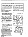
SPIN TEST
.
.
...
.
.
For checking armature, motor winding and brushelectrial continuity.
j
setup
Remove the drive housing from the sprayerasdescribed in "Drive
Housing
Replacement",
Steps
1-6,
page 30.
Remove thepressure control coverandscrews,
the
motor cover, thefan cover(Fl,and
theinspection
covers (Jl. See Fig 7.
Disconnect thetwo leads from the motor to the bridge
( 5 0 8 1 . See Fig 8 and 9.
Armatu'ie Short Circuit Test
Quickly turn the motor fan by hand. If there are no
shorts, the motor will coast two.or three revolutions
before coming to a complete stop.
Fig 7
If the motor doesnot spin freeiy and resists rotation, the
armature is shorted and the motor must be replaced.
See page 31.
Armature, Brushes, and
Motor
Wiring
Open
Circuit Test (Continuity)
Connect the two black motor leads togetherwith a test
lead.
Turn the motor fan by hand at about two revolutions,
per second.
If there is uneven or no turning resistance, check the
following: a) brokenbrush springs; b) brokenbrush
leads: c) loose brush terminalscrews; d) worn brushes;
el broken motor leads; f l loose motor lead terminals.
Repair parts as needed. See page 25.
If there is still uneven or no turning resistance, replace
the motor. See page 31.
Fig 8
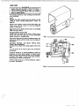
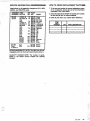
BRIDGE TEST
Remove the bridge from.the pressure control box and
perform this test to determine H the bridgeis funcitonal.
Use a continuity tester, such as multi-meter set on the
X1 ohmsscale ( 0 1.
Eight individualchecks, or tests, must be performed. If
the bridge fails even one test, it must be replaced.
as
Using thechart a t the right, connect the meter wires
indicated by the black dots for each test, then checkthe
continuity.
In Tests 1, 2 and 3, there should be NO continuity.
In Tests 4,5.and 6, connect the + and - meter wires as
indicated, check continuity, thenswitch the meter wire
You should
connections and check continuity again.
get NO continuity oneway,and YES continuity the
other way.
In Tests 7 and 8, connect the meter wires as indlcated
by the blackdots:Touch the indicated"G" wire to one
meter wire, and then to the other. You should get NO
continuity one way, and YES continuity the other way.
Fig 9
Supply
Procedure
Page
General Repair Notes
19
Power
20
ONIOFF S ~ t c h
Circuit Breaker
21
Bridge
21
Circuit Board
22
Pressure Control
23
Calibration
24
Motor Brush
25
Displacement Pump
........................................... 26
Bearing HousingEt Connecting Rod
28
Drive Housing
30
Motor
31
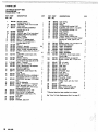
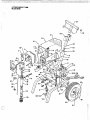
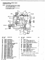
Parts Drawing& List, Ultimate Novam 1000
32
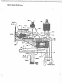
Parts Drawing8 List, PressureControl
34
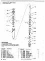
P,arts Drawing & List, Displacement Pump
36
.........................................
...........................................
................................................
.................................................
.................................................
....................................................
...............................................
.......................................................
....................................................
......................
..................................................
.............................................................
............
...................
..............
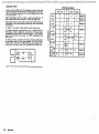
The following tools are needed when repairing this
sprayer.
Phillips screwdriier
Small flatblade screwdriver
Needle nose pliers
Plastic mallet
Adjustable wrench
2" adjustable, open-end wrench
Torque wrench
114" hex key wrench
3/16" hex key wrench
518" socket wrench
318" open end wrench
112" open end .wrench
314" open end .'wrench
718" open end wrench
High quality motor oil
Bearing grease
For cafibration procedure only:
318" ignition wrench
0.015" spray tip
High pressure, oil-filled test gauge, Part No. 820-455
5 gallon pail
Clean water
Mineral spirit!
NEW 3000 p
7 bar)highpressuresprayhose
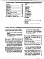
GENERAL REPAlR MOTES
Before repairing any part
of the sprayer, read thefollowing general repair notes and the repair procedure.
Be
sure you have the necessary tools and parts available.
1. When disconnecting wires in the pressure control
assembly, use needle nose pliers
to separate mating
connectors.
When reconnecting the wires, be sure flat
theblade
of the insulated male connector is centered in the
wrap-around blade of the female connector when
the connection is made.
tion, . b e sure to properly mate connectors, and
never pull on a wire to disconnect Pulling ona
wire could loosen the connector from the wire.
it.
2. Route wires in the pressure control assembly
carefully through the legs of the U-shaped bourdon
tube, where appropriate, to avoid interfering with
the bourdontube which moves asthe pressure setting changes and to avoid pinching the wires between the pressure control box and cover.
CAUTION
Improper wire routing can result in poor sprayer
performance or damage to the pressure control.
3.
......
. .
. .:
. .. . ..
'
.-
4. Testyourrepairbeforeregularoperation
of .the
sprayer to be sure the problem is corrected. . .
If the sprayer does not operate properly, review the
repair procedure againto verify that everything
was
done correctly. If necessary, refer to the
Troubleshooting Guide to help identifyother possible' problems and solutions.
including electric
ing parts or elecor a tool while
inspecting therepair.
Shut off the sprayer andunplug it as soon as you
complete the inspection.
Reinstall all covers, gaskets, screws and
before operating the sprayer.
CAUTION
-.
Do-not runthesprayer
dry for..more !han 30
seconds to avoid damaging the pump packings.
5. Reinstallthe motor cover.before regular operation
of the sprayer and replace it if it is damaged. The
cover directs cooling air around the motor to help
prevent overheating. It can also help prevent bums,
fire or explosion; see the WARNING, below.
:
Keep all screws,nuts,washers,gaskets,andelectrical fittings removed during repairprocedures.
These parts are not normally providedwith replacement assemblies.
. .
820-408
19
':
,.
POWER SUPPLY CORD REPLACEMENT
1. Remove the pressure control cover and screws.
2. Disconnect the powersupply cord lead from the
ON/OFF switch /XU).the white wire ooino to the
bridge (W),
and the.green wire to~thegrounding
screw (341). see Fig 10.
3. Loosen the strain relief bushing 1328). Remove the
power supply cord (311).
4. Install the new cord in the
reverse
order
of
disassembly.
5. Reinstall the cover and screws.
"
Fig 10
QNIQFF SWITCH REPLACEMENT
1. Remove the Dressure control
screws.
and
cover
2. U s e a needle nose pliers to disconnect the upper
terminal wirefrom the microswitch (301) for ease in
removing the ONlOFF switch ~302).Refer to Fig
10.
3. Use the pliers to disconnect the two black wires
from the ON/OFF switch 1302). Refer to Fig 10.
4. Use a 5/8" socket wrench to loosen and remove
the nut and rubber boot 13G3) from the toD of the
pressure control box.Remove the switch guard
( 3 0 4 1 . See Fig 9.
5. Remove the ON/OFF switch.
6. Installthe new switchso the internal tab
of the antirotation ring (W) engages with the vertical groove
in the threads of the switch, and the external tab
engages with the blind hole (D) of the pressure controt box. See Fig 11.
7. Install
the
switch guard
internal
(304).
thealigning
tab with the groove in the threads. See Fig 11.
8. Install the nut and rubber boot (303)and tighten.
See Fig 11.
9. Reconnect the wires to the ON/OFF switch (302)
and reconnect the wire to the microswitch (301).
Refer to Fig 10.
10. Reinstall the pressure control cover
and
screws.
n
'
CONTROL BOX
302
Fig 1'1
-.
:.
i
j
. ,...
.', ....
..
...,.
:.:.:
....
.:. :
i
!
BRIDGE RECTIFIER REPLACEMENT (Refer to Fig 12)
!
6. Make surethe bridge isflush with the sideof the box
securely.
and tighten the screws
7. Connect all wires. Carefully route the wires.
~.
1. Remove the pressure control cover and screw.
2. Disconnect all wires from the bridge 1308) a1 the appropriate terminals.
3. Outside the pressure control box on the right side are
two screws (331). Loosen, but don'tremovethe
screw near the back of the control box. Then loosen
all wires carefully to avoidinterference with
and remove the front screw.Slide the bridge out.Route
the movementof the bourdon tube, circuitboard,
4. Slide the new bridge (308)into the box being sure
the lockwasher (3331 on the rear screw (3311 is /N
'FRONTof the bridge. Refer to the Detail in Fig 12.
5. Installthe front screw,lockwasherand nut (332).
8. Reinstallthepressure control cover andscrews.
::
CAUTION
Thelockwashers (333) must be in &nt of the
bridge to avoid overheating which will result in
bridge failure. Refer to the Detail in Fig 12.
CIRCUIT BREAKER REPLACEMENT
5. Push down on the top of the circuit breakerand pull
it out of the box.
6. Install the new circuit breaker in the reverse order of
~
...
.. . ...
.. .. .
_..~
~~~~
1. Remove the pressure control cover and screw.
2. Use a small screwdriverto slide the terminal adapter
off the circuit breaker
terminal.
3. Disconnectthesingleblack
wire from the circuit
breaker (3091 to the ON/OFF switch (3G21 Refer to
Fig 72.
4. Use a 5/8" socket wrench to loosen the nut and boot
(310) on the circuit breaker button.
.
.
disassembly.
7. Reinstall the pressure control cover and screws.
,..,
CAUTION
. ..
the bourdon tube, which will cause a short.
Tighten the circuit breaker nut firmly to prevent
the circuit breaker from turning.
::
..
/ :
-~- ."
..
"
CISaC0l.T BOARD REPLACEMENT
.
.
over ana screws.
2. Turn the pressure control knob all the way counterclockwise to the minimum setting to release spring
tension on the circuit board. Also check to be sure
only three or four threads of the pressure control
knob shaft are exposed below the pressure adjustment nut IS).Back down the nut,if necessary. See
Fi 13.
male connector are cenparound blade of the feconnectionsaremade.
to avoid interferencewith
6. Perform the Stall PressureCalibrationonpage 24
before operating thesprayer.
CIRCUIT BOARD
3. DisconnectALL wires from the board, including the
two heavy black wires. Refer to Fig 14..Pay close
attention to where connections are made.
4. To.removetheboard from the box, pull out the
black DhstiC-tipped Din (330). Push the botfom of
the circuit board toward the wall of the box and
carefully slidethe board out.
5. Install the board in the box at the same angle as it
was removed. Reconnect the wires as indicated in
Fig 14.
1
.. .
..
i:..
..
..
.. ..
... . ...,
.. .
,.
re, follow the Pressure
on page 11 to reduce
i n w from moving
ry.
.
.
5. Remove the pressure control cover and screws
136.87). and disconnectthe four motor leads at the
6.
7.
1. Disconnect the main fluid hose and'the secondary
fluid hose, if used, from the sprayer.
2. Disconnectthe fluid hose (471 from between the
displacement pump outlet nipple 1 4 6 ) and pressure
control inlet elbow (342).
3. Remove the drain tube (126) from the elbow (123).
Hold the pressure control oudet nipple (344)firmly
with a 3/4" open end wrench, end screw the tee
(124) off of the nipple.
4.
I
or installing the new.pressure control
Turning it candamage the sensitive
ube. Hold theadapter firmly with a 3/4"
wrench while screwing onthe tee (124).
Fig 15
8.
9.
appropriate terminals. See Fig 14, page 22.
Refer to "Circuit Board Replacement" on page 22,
remove the circuit board and retain.
Remove the conduit 1221.
Use a l l r ' open end wrench to loosen and remove
the pressure control mounting screws (44) and
washers (40) locatedbelowthe pressure control
box. Remove the box.
Install the new pressure control assembly in the
reverseorder of disassembly. Be sure to reinstall
the conduit seal ( I s n o t shown1 around the wires
in the conduit elbow1 7 7 b l at the pressure control to
prevent motor contaminationfrom entering' the
control box.
10. Perform the pressure control calibration procedure
starting-onpage 24, before regular operationof the
sprayer.
This procedure sets the sprayer to 3ooo psi (210 bar1
NEVER attempt to increase the fluid outlet pressure
byperformingthiscalibration
in any other, way.
MAXIMUM WORKING PRESSURE. This procedure
NEVER
EXCEED
3000 psi (210bar) MAXIMUM
must be performed whenever a new or used circuit
WORKINGPRESSURE.
Normal operation of the
board, or pressure control assembly is removed and
sprayer at higher pressures could result in comporeinstalled or replaced, to be sure the sprayer ispronent rupture, fire or explosion.
pedy calibrated.
AVOID
touching
the
wires
in the
pressure
control
Improper calibration can cause the sprayer to overassembly with your fingers or tools when the control
pressurize and result in component rupture, fire or
box cover is removed to reduce the risk of electric
explosion.4t may also prevent the sprayer from obshock.
taining the maximum working pressure which would
result in poor sprbyer performance.
Caiibratlon Setup 1See Fig 15)
1. Follow the PressureReliefProcedure
Warning on
page 11. Remove the spray hose and gun. Install a
0.015 spray tip in the gun. Connect the gun to the
new test hose and connect the hose to the sprayer
outlet.
2. Remove the pressure contml screws and cover.
3. Remove the secondary ball velve 1 5 0 ) and elbow
188). Holding the nipple (344)with a wrench to prevent it from turning, rotate the tee (124) up and install the test gauge 0 0 in the tee 1124). See Fig 16.
4. Place the pump suction tube in a 5 gallon pail of
clean water.
5. Be sure the gun safety latch is engaged.
6. Use a 3 / 8 ignition wrench to turn the pressure adjustment nut 1s) counterclockwiseabout two full
turns. See Fig 17.
7. With the pressure control knob a t the minimum setting, turn the sprayer svyitch ON. See Fig 16.
1
10.Remove the test gauge assembly. Flush
with mineral spirits.
out water
THE SPRAYER SHOULD NOT STARTI
If it does srart shut the sprayer switch OFF,
disengage the gun safety latch, trigger the gun
into a
waste containeruntil pressure is relieved; Engage
the
gun safety latch. Turn the pressure adjustment nut
(SIa little further counterclockwise. Turnthe sprayer
on to be sure it does not start.
8. Slowly turn the pressure control knob clockwise to
the maximum setting and hold it there. Use a 3/8"
ignition wrench to slowly turn the Dressure adiustment nut (S)clockwise until the test gauge reads
EXACTLY 3000 psi (210 bar).
9. The calibration procedure isnow completed.
.\
. . . i.
... .
a
:.. ....
NOTE:
!
..
. .-
New.motor brushes are included with each
Packing RepairKit No. 820041. Replacethe
brushes when
replacing
the
packings,
and/or when the brushes
have
been
worn to
a minimum of 9 / 1 6 on the longest side.
I
I
I
1.
2.
3:
4.
5.
6.
Remove the six motor cover screws (321 and motor
cover (141. See Fig 18.
Remove the screws (H),inspection covers (J) and
gaskets iK1 on each side of the motor. See Fig 18.
Loosen the brush lead terminal screw and remove
the lead.
Push down on the spring clip slightly then pull the
clip away from and out of the brush holder. Refer
fo
Fw 19. Keep the spring clip.
Remove and discard the brush.
Inspect the commutator for excessive pitting, burning or gouging.
fin
SPMNICLIP
1
r B R U S H HOLDER
NOTE: A black color on the commutator is normal.
Have the commutator resurfaced by a
qualified motor repairshop if the brushes
seem to be wearing too fast. '.
Place a new brush in the holder so the beveled
edges are as shown in the first part of Fig 19, and
is routed as shown in the second part
the brush lead
of Fig 19.
8. Slowly push the tabbed end of the spring clip into
the brush holder until the clip tab engages in the
holdwand the rolled portion of the tension spring
rests squarely on the brush.
9. Route the brush lead
to the terminal andtighten the
terminal screws. Be sure the brush lead does not
touch any pert of the armature or motor housing.
10. Test the brushes:
a. With the ON/OFF switch OFF, turn the
pressure control knob all the way counterclockwise to minimum pressure. Plug in the sprayer.
b. Turn the ON/OFF switch ONand slowly increase the pressure until the motor comes up to
full speed.
c. Inspect the brush and commutator contact
area
for excessive arcing. Arcs should not "trail" or
circle around the commutator surface.
TOR
7.
SIDE, VIEW OF MCTOR BRUSH INSTALLATION
INSULATION PIATE
TERMINALSCREW
BRUSH LEAD
SPRING CLIP
.
..
. ~.. .
.
.......,
.
..
.
CAUTION
Do not run the sprayerdn/ for morethan 30
seconds whilecheckingthebrushes
damaging the displacement pump.
to avoid
17. Reinstall the brush inspection covers, gaskets, and
screws. Reinstall the motor cover and screws.
DETAIL OF MOTOR BRUSH
SHOWN WITH MOTOR LEAD
FACING BACK OF MOTOR
Fig 19
820-408
25
Removing the Pump (Refer to Fig 20)
1. Flush the pump, if possible, and relievepressure
again. Stop the pump with the piston rod (2231 in
its loweq position. To lower it manually, carefully
rotate the blades of the 'Tan with a screwdriver.
2. Remove the clamps holding the drain tube ( 1 2 6 ) to
the displacement-pump.
3. Unscrew the suction tube (42)from the pump. Hold
the wrench on the pump intake valve (222)to keep
the purhp from loosening.
4. Unscrew the hose (47)from the nipple (46)on the
pump outlet andremove the hose. .
5. Use a screwdriver to push the retaining spring3
i5
)
aside and push out the pin (20).
6. Loosen the locknut (38)andunscrewthepump
from the bearing housing (27).
Fig 21
'
Disassembling the Pump(Refer to Figures21 and221
1. Unscrew the intake valve (222) from the cylinder
(2161..Remove the gasket (2061, ball guide (215).
stop pin (207) and ball (204) from the valve. Clean
and inspect the parts
for wear or damage, replacing
parts as needed. Always usea new gasket (included in Repair Kit 820-041 1.
2. Unscrew andremove the packing nut (221) and
plug (201).
3. . Use a plastic mallet to tap the piston rod down,
then pull the rod out through the boftorn of the
cylinder.
4. Remove the throat packings
218) and glands
(211,212).
(209.
!
LIPS OF
\I-PACKING IN
THROAT FACE DOWN
5. Clamp the flats of the piston rod in a vise. Use a 7/8
in. wrench to loosen the retaining nut (214).Then
use the wrench to unscrew the piston valve (224)
6.
from the rod.
Remove the backupwasher
(219). wiper (205),
packings (208, 217) and glands (213, 2 2 0 1 .
*2171PLASTICI
LIPS OF V-PAC
Fig
P
26820-408
Fig 22
Reassembling the Pump
Assembly Notes:
(1) U s e Repair Kh 82C-041 to repair the displacement
pump. Reference numbers in parentheses with an
asterisk, for exsmple, (210*), show the parts included in the kit. Use all the new parts even if the old
ones still look good for the best results.
.. -..
(2) Alternate leather and plastic packings as shown in
Notice that the lips of the throat "VpackFig
ings facedown, against pressure, and the lips of
the piston "r'packings face up, against pressure.
The lips of the U-cup wiper (205"). face dawn. Inc o r m installation damages the packingsand
results in the pump leaking.
22.
MARK PACKINGS
AND HiX ALIGNMENT
13) Cost the piston rod, inside of the cylinder and the
,
packings with a lightweight oil to helpprevent
packing damage when inserting the piston rod.
1. Check the outside of thepiston rod ( 2 2 3 ) and the in-
side of the cylinder (216) for scoring or scratches.If
the parts are damaged, new packings will not segl
property. Replace these parts if needM.
2. Stack thebackupwasher
(219"). wiper (205*),
femalegland (2209, packings (217", 208') and
malegland
(213") onto the piston. valve. See
Figures 23 and 24.
3. lighten the packing retaining nut (214) onto the
piston valve(224) and torque to 3 to 4 in-lb (0.34to
0.35 Nm)-about finger tight.
4.
Use a pen to make a light mark on the packings
where they align with one of the flats on the nut.
See fig 23.
5. Place ball (203') on piston valve (224). Apply one
drop of thread locking compound onthreads of
valve. Then hand tighten the valve assembly into
the piston rod just until the nut meets the face of
the rod. See Fig 24.
Fig 24
9. Install
the
packing
nut (221) and plug (201) but
leave loose for now.
6. Place the flats of the rod in a vise.
critical. Follow the procedure
carefully to avoid
damaging the packings by overtightening.
7.
,,. .. .. . .,
...
. ...
c,.:.
,.7?
j ,
,;
.,. .. ...
.-.
8.
Without changing ?he tightness of the nut ag8inst
the packings, tighten the nut (214) into the piston
rod to 18 to 20 fi-lbs (24 to 27 Nm). If the pen mark
on the packings loses alignment, back the nut off
and try again.
Stack the male gland (2119, packings (218'. 209')
and female gland(212"). one at a time, into the top
of the
cylinder. See Fig
22.
4
10. Insert the piston rod (223) through the bottom of
the pump cylinder, pushingit up until thetop of the
pistonrod extends 1-718 in. (32.2 mm).beyondthe
top cylinder.
of the
See Fig 22.
:.
:
..
11. Screw downthecylinder locknut (38) until it is
finger tight at the bottom of the external cylinder
threads.
12. Place flats of the intake valve in a visa. Install anew
gasket ( 2 0 6 1 ) and screwthe pump cylinder into the
valve. See Fig 21.
:...
!,
13. Screw the dsplacement pump about
3/4 of the
way into the bearing housing (27).Hold the pin (201
up to the pin hole in the connecting rod assembly
(31and continuescrewing in the pump until the pin
slides easily into the hole. Back oif the pump until
the top threads of the pump cylinder areflush with
the face of the bearing housing andthe outlet nipple (46)is straight back. Push the retaining spring
135) into the groove all the way aroundthe connecting rod. Tighten the locknut (38)very tight-about,
70 ft-lb (94Nm)-with a 2 in. open-end wrench and
a light hammer. Refer to Fig
3
25.
~
~~
14. Tighten the packing nut (221)just enough to stop
leakage, but no tighter. Fill the wet-cup/packing
nut 1/3 full with Graco TSL.
15. Replacethemotorbrushes,included
kit. See page 25.
with the repair
Fig 25
€
..
. .
1. Stop the sprayer.at the bottom of its stroke to get
the crank (E)in its lowest position. If the crank (E)
must be lowered manually,carefully
rotate the
blades of the fan with a screwdriver.
2. Remove the front cover and screws (31, 32).
3. Remove the clamp holding the drain tube (126) to
the displacement pump.
4. Unscrew the suctiontube (42) from the pump,
holding a wrench on thepump inmke valveto keep
thepump from loosening.
5. Disconnectthepump outlet hose (47) from the
I
displacement
pump
outlet nipple (46).
6. Use ascrewdriver to pushaside the retainingspring
(35)a t the top of the pump. Push the pin (20) out
the rear.
7 . Loosen the jam nut (38)with an adjustable wrench.
Unscrew and remove the displacement pump.
8. Use a 3 / 1 6 hex key wrench to remove the four
screws (33)and lockwashen (49)from the bearing
housing.
9. Lightly tap the lower rear of the bearing housing
(27)with a plastic malletto loosen it fmm the d t i k
housing.Then pull the bearinghousingandthe
connecting rod assembly (3) straight off the drive
housing.
10. Inspect the crank (E) for excessive wear and replace
pans es needed.
11. Evenly lubricate the insideof the bronze bearingin
the bearing housing with high quality motor oil.
Liberally pack the roller bearing in the connecting
rod assembly (3) with bearing grease.
12. Assemble the connecting rod and bearing housing
(27).
13. Clean the mating surfaces of the bearing and drive
housings.
14. Align the connecting rod with the crank (E) and
carefully align the locating pins
in the drive housing'
with the holes in the front cover (31). Pushthe
bearing housingonto the drive housing tap
or it into
place with a plastic mellet.
31
Fig 26
(351 into the groove all the way aroundthe connecting rod:Tighten the locknut (38)very tight-about
70 ff-lb (94 Nm)-with a 2'in. open end wrench
and a light hammer. See Fig 25,' page 28.
CAUTION
15. Installthe screws (33)and lockwashen (49) on the
bearing housing andtighten evenly.
16. Screw the displacementpumpabout 3/4 of the
way into the bearing housing(2). Hold the pin (20)
up to the pin hole in the connecting rod assembly
(3) and continue screwingin the pump until the pin
slides easily into the hole. Back off the pump until
the top threads of the pump cylinderare flush with
the face of the bearing housingand the outlet nipple (46) is facing back.Push the retaining spring
cted through theair and result
jury or property damage, inthe pump, connecting rod or
17. Reinstall the front cover and screws(31,321. Reconnect the suction tube (42) and pump outlet hose
(471.
'
MOTE:
Stop the sprayer at the bottom of its stroke
to get the crank (E)in its lowest position.To
lower it manually, carefully rotate the blades
of the fan with a screwdriver.
1. Remove'the'front cwer and screws (31,32).
2. Disconnect the pump outlet hose (47) from the
displacement pump outlet nipple (46).
3. Remove the clamps holding the drain tube (1261 to
the disp!acement pump.
4. Use a 3/16" hexkey wrench to remove the-four
screws (33)and lockwashen (49)from the bearing
housing.
5. Lightly tap the lower rear of thebearinghousing
( 2 7 1 with a plastic mallet to loosen it from the drive
housing. Then pull the bearing housing and connecting rod assembly straight off the drive housing.
6. Use a 1/4" hexkey wrench to remove the two
screws (51 I and lockwashers(651from the recess of
thedrive .busing and the two screws (301 and
lockwashers (651 from the rear of the motor front
end bell (lb).
7.
Fig
30
820-408
CAUPlON
DO NOT allow the gear cluster (9) to fall when
removing the drive housing(2). It is easi& damaged if dropped.Thegearmaystayengaged
in
either the front end bell or the drive housing.
DO'NOT lose the thrustballs (10) located a t each
end of the gear cluster(91or allow themto'fall between.gears.Theball, which is heavily covered
with grease, usually stays in the shaft recesses,
but could be dislodged. If caught between gears
and not removed, the balls will seriously damage
the drive housing. If the ballsare not in place, the
bearings will wear prematureiy.
8. Liberallyapplybearing grease to the gearcluster
(91. Check to be sure the thrust balls (IO)are in
place.
9. Place the bronze-colored washer' (2a) on the shaft
+ protruding from the big gear in the drive housing
(2). Align thegears and pushthe new drive housing
l and locating pins.
straight onto the front end be
13. Starting at Step 6 and workingbackwards,continue to reassemble the sprayer.
.
Tools Needed:. .
Adjustable Wrench
Phillips screwdriver
Plastic mallet
114"
hex
k e y wrench
3/8" open end wrench
Needle nose pliers
Bearing grease
.
13. Use a plasn'c mallet to gently tap the displacement
pump (39)from the rear to loosen the drive housing
from thefront end bell. Thenpull the drive housing
away from the end bell.
CAUTION
DO NOT allow the gear- cluster (9) to fall when
removing the drive housing
(2). It is easiM damag
ed il dropped. The cluster may stay engaged in
either the front end bellor the drive housing.
DO NOT lose.the thrust balls (10) locatedat each
end of the gear cluster (9) or allow them to fall
between gaan. The ball, which is heavily covered
with grease, usually stays in the gear recesses, but
could be dislodged. If caught betwaen gears and
not removed, the balls will seriously damage the
drivehousing. If theballsare not in place, the
bearings will wear prematurely.
1. Remove the clamps holding the drain tube 1126) to
, the displacement pump.
2. Disconnectthe pump outlet hose-(47) fromthe
displacement pump outlet nipple (46).
3. Remove the screws (871 and presshre control cover
(36)and disconnect thefour motor leads.
4.Usean
adjustable wench to loosen theconduit
connector nut ( n a ) at the
pressure
control
assembly (43).
5. Swing the conduit ( 2 2 1 away fromtheconduit
elbow (77b).
6. Pull the motor leads through the elbow,one at a
time.
..
.
7.
Loosen the nut of the connector (77a) a t the motor
and pull the conduit ( 2 2 1 a h y from the motor,then
pull the leads through the conduit, one at a time.
8.
Unscrew the connector
elbow
(77b)
from
the
. .
motor.
9. Pull the wires through ttie elbow, one at a time.
10. Remove the front cover and screws (31,32).
11. Use a 114" hexkeywrench to remove the two
screws (51) and washers165) from therecess of the
drive housing, and thetwo screws (30)and washers
( 6 5 1 from the lower rear of the motor front end bell
(lb).
12. Remove the motor cover (14) and screws (32).
.,.
:
:Y
, .
. .. . ..,.. .
.. .... .......
-..<&.*'
wrench to removethe two
14.Use a 114"hexkey
screws 141)and lockwashers (62)from the underside of the motor mounting frame. Be sure to support the motor to keep the sprayer from tipping.
15. Lift the motor assembly off the frame.
16.Place thenew motor assembly.on'the frame and
align with theframe mounting holes. Installthe
screws (411 and lockwashen (62)tightly.
17. Liberally grease the gear cluster (9) and pinion gear
(01 and pack all bearings in the motor front end
bell. Check to be sure the thrust balls (10) are in
place.
on.the.shaft
18.Place the bronzecolored washer (2)
protruding from the
big gear in the drive housing(2).
19. Align the gearsandpush
the drivehousing (21
straight onto the front end bell and. locating pins.
Starting at Step 12 and working backwards, continue to reassemble the sprayer.
NOTE:
Use a turning motion on theconduitwhen
feeding wires through
21. Reinstall the conduit seal (138not shown) around
the wires in the conduit elbow I 7 7 b ) at the pressure
control to keep contaminants .from enteringthe
pressure control.
Reinstall the motor cover and pressure'control
cover.
20.
it.
'
22.
!
"
___yr_~*."_
l.y_G"
,,.,:
?
.
i
:
:
;
:
:
~>
~-
~ ~ , . ~ ~ . ~ ~ ~ . ...,...
~ ~ ~; . -. : ~, : ~ : ~~ ~~~ ,, ~~ ~ ~: : ~ - ~: . .~ ~ ~~- ~. ~~~ . ~ ~ - ~ ~ . ~ : -
PARTS L E T
ULTIMATE NOVAm 1
m
. .
Model 82LM40
Includes kerns 1-139
REF PART
DESCRIPTION
QTY
NO. NO.
1
REF PART
NO.
820369 MOTOR,
elecnic
58
Includes items lb, IC
1
l b 820-453 .HOUSING, motor (front endbell)
1
IC 820379 .FAN, motor
1
2
8 2 0 3 7 1 DRIVE
HOUSING
ASSEMBLY
2b
1
Includes item
2a 820-380 .WASHER.
1
2b glo-405 .GREASE,
gear,
10oz.(not shown)
'
1
3
820365 CONNECTING ROD ASSEMBLY
1
6
820364 CART
FRAME
1
9
820373 GEAR
CLUSTER
1
10
820457 BALL, 1/4"; stainless steel
2
14
820-372 MOTOR COVER ASSEMBLY;
37,91 labels
Includes
1
20
820308 PIN
- 1
22
820323 CONDUIT,
electrical
8 in.
27
820-359
BEARING
HOUSING
ASSEMBLY
1
31
820-370 FRONT COVER; includes label &l
32
820307 SCREW, machine, filh; No. E32 x 1"
long
10
33
820-416 CAPSCREW.. socket
head: 318 x
.
1.75" long
4
33
820305 SPRING.
retainina
1
36
820367 COVER,.pressure-contml; indudes
1
four of item 87 andlabels 93 & 109
37 ~ 7 9 8 8 5'LAEEL, 'Warning"
1
38
820353 NUT,
hex;
1-5/8" thread
1
39
820356 PUMP,
displacement;
ssa separate
parts list on page 36
1
40
820258 LOCKWASHER, 5/16"
2
CAPSCREW,
socket
head;
5/16 x
41'
820-417
0.5" lono
2
4~
820-399 TUBE. siction
1
43
820-361 PRESSURE CONTROL ASSEMBLY;
See separate
parts list on
page 37
1
44
820-406 CAPSCREW. hex head 1/2 x 0.625"
long'
'
.
2
45
820329 PLATE,
designation
1
46
820421 NIPPLE, 1/4 npt(mJx 114 npsm(mJ
2
47
820378 HOSE, grounded, nylon; 1/4" ID;
cpld 1/4 npsmlf); 29" (715 mml Ig;
guard
spring
both ends
1
49
820315 LOCKWASHER,
spring;
3/8"
4
50
820-368 BALL
VALVE,
1/4 npt(mbeJ
2
51
820-419 CAPSCREW,
socket
head;
1/4 x
2.75" long
1
55
E20-260
7
~ .SPACER
-~
.
68
820-261 AXLE
5?
820264 WASHER, plain; W8"
2a.
~
~~
59
60
62
63
65
€6
67
DESCRIPTION
NO.
820-401 CLIP, spring
820263 CAP, hub
820265 WHEEL
820310 LOCKWASHER, spring; 5/16"
820-452 BUSHING, 3/4 npt(mJx 112 nptlf)
820273 LOCKWASHER, spring; 1 / 4 "
820-319 TAG. wamina
8
2
0
a
n
820322
E4
E7
820014
820325
88
820410
89
91
820-398
820037
93
820435
.82Mx36
109
'"178934
'V7-762
119
820-486
121
820423
€20415
123
124
125
126
127
1m
129
130
131
132
133
134
135
136
137
138
139
RIVET. blindCONNECTOR, conduit
THROATSEALLIQUID,8 oz.
SCREW,machine,'ovalhead;thread
forming; No. 10-24. Tvpe C; 0.5"
long
ELBOW,street; 1/4x 1/4 nptlrnxfl
MOUNTINGBRACKET
LABEL,
identification
LABEL, identification
LABEL.
identification
LABEL,warning
LABEL,
WARNING
CAPSCREW, button headsocket;
1/4-2oxo.6Y
CIRCUITBOARD, see page 35
ELBOW,female, XIo; 1/4 npt one
end
TEE, 1/4 npt(fJ
TEE. I F x F x M 1
TUBE, drain
CLIP. sDrina
CLIP; ;brine
STRAINER. fluid
PLUG, tube
HANDLE, frame
SLEEVE, frame
PIN, spring, straight
BUTTON, snap
SCREW,mach.pnh;
No. 10-24
x 0.25"
NUTCAPSCREW.
hd
...
. soc
..~
SEAL, conduit (see page 3 4 1
SCREW,
machine,
flat hd
82Q-m
820490
820-491
820413
'
am
2
2
2
2
1
5
1
2
2
1
.. ..
1
2
1
2
1
1
1
1
1.
1
1
1
2
1
1
1
1
.
**Warning labeh.and tags supplied at no charge.
See "How To Order ReplacementPam"on page 37.
"~
. .
..I ..
,.:: ... i,.: . :\. , ..,'.
.
. . .. .
. . .. .. . :...,
. ...: , ,
. ..~
-, ,
,
..
32820-108
. .
ULTIMATE NOVAm low)
Model 82o040
... .
..
.. .
..
... .
PRESSbRE
CQkMTRQ
ASS€MBLY
L
1
1
Includes items 301 to 345
MOTE: Acircuit board is not induded with the pressure
control assembly 820-361. Order part no.
[email protected]. 121, page 32)separately.
The terminals listed in this parts list are shown in
the wiring diagram on page 35.
REF PART
NO. NO.
301
302
303
304
305
306
DESCRIPTION
QT\I
820-450 MICROSWITCH
820342 ONlOFF SWITCH
820341 BOOT, ON/OFF switch
820-433 GUARD, locking
82C-451 JUMPER WIRE
0-375 BARE PRESSURE CONTROL BOX
Includes items 302,303,304
820362 BRIDGE, rectifier, SCR
820-366 CIRCUIT BREAKER
1
1
1
620-43 BOOT, circuit breaker
0-363 CORD, power supply
1
1
308
309
310
31 1
312
314
316
820-442 ADAPTER, terminal
820-4ill TERMINAL,
male
W-444 .TERMINAL,
male
317
8 2 0 4 4 5 ,
TERMINAL,
male
318
820-437 TERMINAL,
female
319
820-435 TERMINAL,
female
320
620-440 TERMINAL,
female
321
820-423 TERMINAL, male
322
820430 TERMINAL,
female
3230-439
TERMINAL,
female
324
62046 TERMINAL,
female
325
%&&a TERMINAL, ring
327
820448 LOCKWASHER,
No.
328
820-431 BUSHING,
Strain
relief
329
820434 TIP,
pin,
black
plastic
34ElZkm3
REF PART
DESCRIPTION
QTY
No. NO.
820449 PIN
330
331
820427 SCREW,
machine,
1
flat head;
No. 10-24 x-5/8" long
820425 - NUT, hex, m r , NO. 10-24thd
33
820-426 LOCKWASHER,
internal,
shakaproof;
No. 10
334 **178797 LABEL, WARNING
335 *'178035
LABEL. WARNING
3324
1
1
1
3
2
EO-W
337
338
341
342
343
344
345
1
1
1
3
1
1
TERMINAL,
mala
820-446
TERMINAL,
female
820447.
mala TERMINAL,
820-424 SCREW,
mach. slotted
pan
hd;
No.
8x5116" long
820-410
ELBOW;
street; 1/4n p t h x f )
820-322 CONNECTOR, conduit
82fi4U NIPPLE, 1/4npt
& W 1
NIPPLE, 114 npt(m)x 1/4npsm
2
2
2
-
1
1.
2
1
.. . ..
..
1
1
1
1
1
1
'> :
307 number in description refers to separate instruction
manual.
"Warning labels and tags supplied at no charge.
i
. . ,.
. ... . . .
See "How To Order ReplacementPam" on page37.
8, internal
..
. ..... .
,
. .
6
..
. .
. ~.
. . .. ..
..
. . ...
I.
:
. .
... .
.. . . .
:.::I
Displacement Pump, 820356. Serleg
Includes items 201 to 224
B
I
@
<e>
213f
.. .
217'
216-
'207
. .. ,
..
I
Repair Kit 820041
(Must be purchased separately)
. ..
For pump packings andmotor brushes.Includes all
starred ( 1 ItemsIn parts list below,plus two motor
brushes.
REF PART
DESCRIPTION
NO. NO.
1
204
1
1
205
206
207
2tQ1
203
211
212
213
36
PLUG
BALL
*820-277 BALL
. *820-381
SEAL, u-cup
'
8
2
0
3
5
2 GASKET
'
8
2
0
3
8
2
PIN, ball
stop
*820-?83 leather
V-PACKING,
*820-3&1
V-PACKING,
leather
'
6
2
0
male
3
8
packing,
5
GLAND,
'
8
2
0
3
8
6GLAND,
packing,
female
*82a387 packing,
GLAND.
male
820-408
REF PART
'NO. NO.
214
215
216
217
1
1
218
219
1
2
2
1
1
1
.
..
an
820-395
203 '820-276
201
.
220
221
'
222
223
224
DESCRIPTION
820-388
820-389
820354
NUT, hex
GUIDE, bal
CYLINDER
V-PACKING,
plastic
'820-391
V-PACKING, plastic
*E20492 WASHER, backup
W0-393
GLAND, packing
820-394 NUT.
packing/wet-cup
820-365 VALVE,
intake
820-357
ROD,
piston
820-360 VALVE,
piston
*820-390
See "How To Order Replacement parts" on page 37.
~
.
an
.
1
1
1
3
3
1
1
..
..:,.:...
,.:
,
:./
;. ... .::.
., ...
.
, ,. . . .
. . . .:..
.
..:
.,
1
1
1
1
,
.:
.. .
. ......
. .. .
..
... .
..:
..
,
SERVICE INFORMATION
HOW TO ORDER REPLACEMENT PART§
Listed below by the assembly changed areOLD, NEW,
ADDED, and DELETED parts.
1. To be sure you receive thecorrect replacement parts,
kit or accessories, always give all qf the information
ASSEMBLV PART
'CHANGED.
STATUS
8p-040
Sprayer
REF PART
NO. NO.
NAME
ADDED (6)
32 820-307 Screw
DELETED (61 33 820-416 Screw
OLD
820-268 Ball Valve
NEW
50 820-368 Ball Valve
ADDED 14)
57 820-264 Washer
DELETED I l l 65 820273 Lockwasher
DELETED
118 820407 Lockwasher
OLD
820418 Capscrew
NEW
119 8xl" capscrew
OLD
NEW
requested in the chart below.
2. Check the parts l i i to identify the c o r n part number;
do not use the ret. no. when ordering.
3. Order all parts from your nearest Graco distn'butor.
I
6 &@it
PART
NUMBER
PART DESCRIPTION
820-409 Tee
124 820-487 Tee
NEW
OLD
NEW
ADDED
ADDED
ADDED
ADDED
820-356
PUmD
to
series B
OLD
NEW
820-392 Washer
219 KZC-492 Washer
I NTERCHANGEABtLITY NOTE The NEW part is intel
ch;angeable with the OLD part listed directly above it.
QUANTITYCHANGENOTE:Thenumber
theses in the Status columnindicatethe
changed.
in parenquantiq
...
. ...
..:.,: :.:.
. . ,..
..
.
i: c: ,
..
.. ..
. .. .
.
.. .. ..
..
.......~.
,..,.
. . ...
. .
~
TECHNICAL DATA
Power Requirements
Operating Range
Cycles/Gallon (liter)
Maximum Delivery
Power Cord
Inlet Paint Strainer
: 115 VAC, 60 Hz, 1 Phase, 15 AMP minimum
: 5OR3GDO psi (35-210 bar)
: 200 ( 5 3 )
:
.85 GPM (3.2liter/min)
: No. 14 AWG, 3 wire, 8'6" 12.5 m) long
: 16 mesh, 1190 micron,
. ..
. .
Stainless Steel Screen, reusable
Pump Inlet Size : 3/4 npt w/3Oo I.D. chamfer
FluidOutlet Size : Primary: 1/4 npsm(m)
Secondary: 114 npt(m)
Weight : ,100 Ib ( 4 5 Kg) approximately
Wetted Parts : Aluminum;Delrin,Nitralloy,Nylon,Polyethylene,
Polyurethane, Rubber impregnated leather,
Stainless Steel, Tungaen Carbide,
Zinc-plated Steel
Dimensions : width: 22.5 1571.5 mm)
Height: 28.0" (711.2 mm)
Length: 26.0" (660.4 mm)
.. .
.:
.. . .
..-.:..: . .
., ..
...... . ,:: ',
,..:. . ,..
... , ..
. ... . .,.
:;
,
...
....... .
~~