1
2HA/2HB
2-2 Electrical Parts Layout
2-2-1
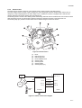
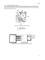
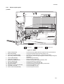
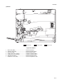
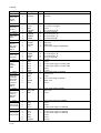
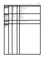
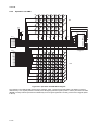
Electrical parts layout
(1) PWBs
5
6
1
13
12
7
4
10
9
2
3
11
8
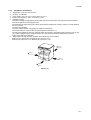
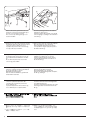
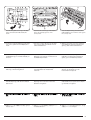
Machine front
Machine inside
Machine rear
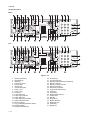
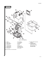
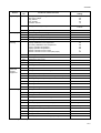
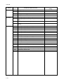
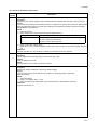
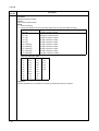
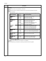
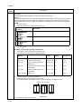
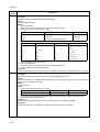
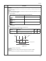
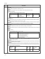
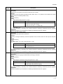
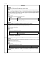
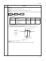
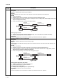
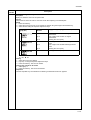
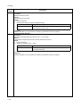
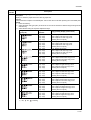
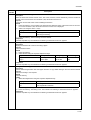
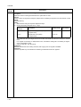
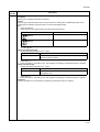
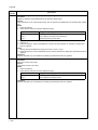
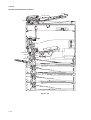
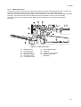
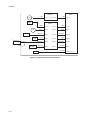
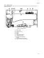
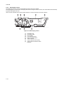
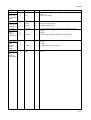
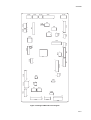
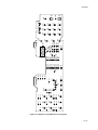
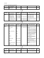
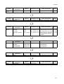
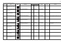
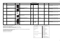
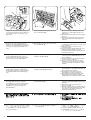
Figure 2-2-1 PWBs
1.
2.
3.
4.
5.
6.
7.
8.
9.
10.
11.
12.
13.
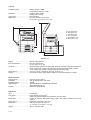
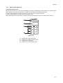
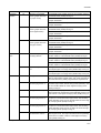
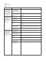
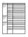
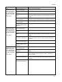
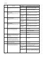
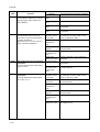
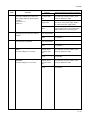
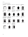
Engine PWB (EPWB)................................... Controls the other PWBs, electrical components and optional devices.
Main PWB (MPWB) ..................................... Controls the operation panel and laser scanner unit.
Power source PWB (PSPWB) ..................... Generates +24 V DC and 5V DC; controls the fuser heater.
High-voltage PWB (HVTPWB) ..................... Main charging. Generates high voltages for transfer and high voltages for
separation.
Inverter PWB (INPWB) ................................ Controls the exposure lamp.
CCD PWB (CCDPWB)................................. Reads the image off originals.
Operation unit PWB (OPWB)....................... Consists of the operation keys and display LEDs.
Drawer PWB (DPWB) .................................. Controls the electrical components.
APC PWB (APCPWB) ................................. Generates and controls the laser light.
PD PWB (PDPWB) ...................................... Controls horizontal synchronizing timing of laser beam.
Registration motor PWB (RMPWB) ............. Controls the registration motor.
LCD PWB (LCDPWB).................................. Controls the display of LCD.
Printer board PWB (PRNPWB).................... Controls the printer functions.
2-2-1