1
General Specifications and ...
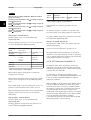
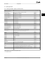
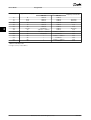
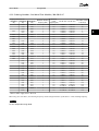
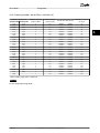
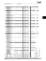
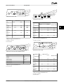
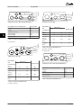
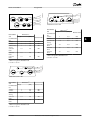
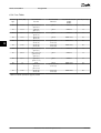
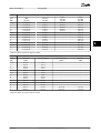
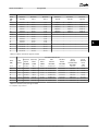
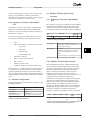
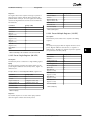
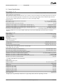
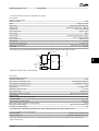
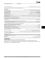
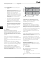
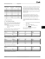
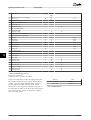
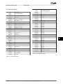
No. Description
Design Guide
Warning
Alarm/
Trip
Alarm/Trip Lock
Parameter Reference
7
DC over voltage
X
X
8
DC under voltage
X
X
9
Inverter overloaded
X
X
10
Motor ETR over temperature
(X)
(X)
1-90
11
Motor thermistor over temperature
(X)
(X)
1-90
12
Torque limit
X
X
13
Over Current
X
X
X
14
Ground fault
X
X
X
15
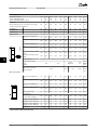
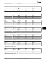
Hardware mismatch
X
X
16
Short Circuit
X
X
17
Control word timeout
18
Start failed
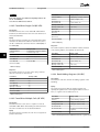
23
Internal Fan Fault
X
(X)
(X)
8-04
X
24
External Fan Fault
X
25
Brake resistor short-circuited
X
14-53
26
Brake resistor power limit
(X)
(X)
27
Brake chopper short-circuited
X
X
28
Brake check
(X)
(X)
29
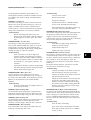
Drive over temperature
X
X
X
2-13
2-15
30
Motor phase U missing
(X)
(X)
(X)
31
Motor phase V missing
(X)
(X)
(X)
4-58
32
Motor phase W missing
(X)
(X)
(X)
4-58
33
Inrush fault
X
X
34
Fieldbus communication fault
X
4-58
X
35
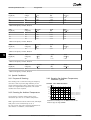
Out of frequency range
X
X
36
Mains failure
X
X
37
Phase Imbalance
X
38
Internal fault
X
X
39
Heatsink sensor
X
X
40
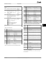
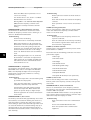
Overload of Digital Output Terminal 27
(X)
5-00, 5-01
41
Overload of Digital Output Terminal 29
(X)
5-00, 5-02
42
Overload of Digital Output On X30/6
(X)
5-32
42
Overload of Digital Output On X30/7
(X)
46
Pwr. card supply
47
24 V supply low
48
1.8 V supply low
49
Speed limit
50
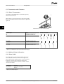
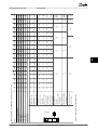
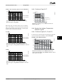
AMA calibration failed
51
AMA check Unom and Inom
X
52
AMA low Inom
X
53
AMA motor too big
X
54
AMA motor too small
X
55
AMA Parameter out of range
X
X
56
AMA interrupted by user
57
AMA timeout
58
AMA internal fault
X
5-33
X
X
X
X
X
X
X
X
(X)
1-86
X
X
X
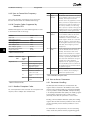
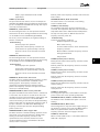
59
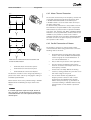
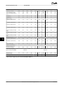
Current limit
X
60
External Interlock
X
X
62
Output Frequency at Maximum Limit
64
Voltage Limit
X
65
Control Board Over-temperature
X
66
Heat sink Temperature Low
X
MG11BC02
9 9
X
X
Danfoss A/S © Rev. 06/2014 All rights reserved.
X
171