1
Design Guide
130BA175.12
L1
L2
L3
N
PE
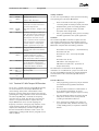
a.
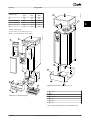
Aluminium-clad with copper wire
b.
Twisted copper wire or armoured steel wire cable
c.
Single-layer braided copper wire with varying
percentage screen coverage
This is the typical Danfoss reference cable
d.
Double-layer braided copper wire
e.
Twin layer of braided copper wire with a
magnetic, screened/armoured intermediate layer
f.
Cable that runs in copper tube or steel tube
g.
Lead cable with 1.1 mm wall thickness
F1
91 92 93 95
12
37
L1 L2 L3 PE
U
6 6
V W PE
96 97 98 99
18
50
53
55
5 kΩ
54
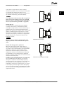
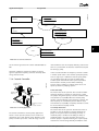
Transfer impedance, Z
t
mOhm/m
105
a
104
b
175ZA166.13
Electrical Installation
Transmitter
M
3
c
102
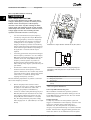
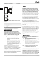
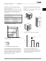
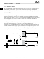
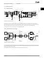
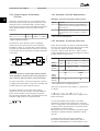
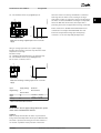
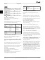
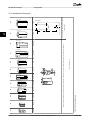
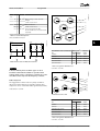
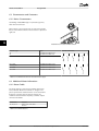
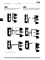
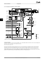
Illustration 6.63 Electrical Connection Diagram
101
d
1
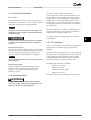
6.8.2 Use of EMC-Correct Cables
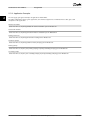
Danfoss recommends braided screened/armoured cables to
optimise EMC immunity of the control cables and the EMC
emission from the motor cables.
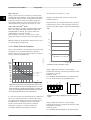
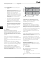
The ability of a cable to reduce the in- and outgoing
radiation of electric noise depends on the transfer
impedance (ZT). The screen of a cable is normally designed
to reduce the transfer of electric noise; however, a screen
with a lower transfer impedance (ZT) value is more
effective than a screen with a higher transfer impedance
(ZT).
10ˉ1
e
10ˉ2
f
10ˉ3
0,01
0,1
1
10
100 MHz
g
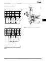
The lower the Z the better the cable screening performance
103
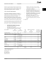
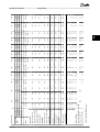
Illustration 6.64 Transfer Impedance
Transfer impedance (ZT) is rarely stated by cable manufacturers, but it is often possible to estimate transfer
impedance (ZT) by assessing the physical design of the
cable.
Transfer impedance (ZT) can be assessed on the basis of
the following factors:
• The conductibility of the screen material
118
•
The contact resistance between the individual
screen conductors
•
The screen coverage, i.e. the physical area of the
cable covered by the screen - often stated as a
percentage value
•
Screen type, i.e. braided or twisted pattern
Danfoss A/S © Rev. 06/2014 All rights reserved.
MG11BC02