1
Installing and Wiring Your Module
3-5
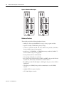
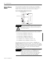
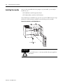
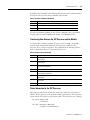
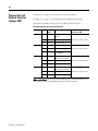
Figure 3.5 JW4 Pin Assignments and Settings
SER
SLC 500
BASIC MODULE
CAT
FRN
Pin Assignments
SERIAL NO.
2 4 6
1 3 5
JW1
9 87 6
UL
9 87 6
54 3 2 1
PRT2
SA
DH485
JW2
PRT1 Port = ASCII interface port
PRT2 Port = ASCII interface port
DH485 Port = Program port with DH485 protocol
(shipped configuration)
54 3 2 1
PRT1
PRT1 Port = Program port with default
communication settings
PRT2 Port = ASCII interface port
DH485 Port = Run-time DH485 only
PRT1 Port = Program port with programmed communication settings
PRT2 Port = ASCII interface port
DH485 Port = Run-time DH485 only
PRT1 Port = Program port with programmed communication settings
PRT2 Port = DF1 protocol
DH485 Port = Disabled
IMPORTANT
The first setting shown above is the default configuration. When
the jumper is set in this position, the module always powers up in
Command mode at 1200 baud, no parity, 8 data bits, and 1 stop
bit.
ATTENTION
IMPORTANT
All other jumper settings for JW4 are illegal and may cause
damage to the module.
• When DF1 protocol is selected for port PRT2, port DH485 is
not available for DH485 programming or run-time operation.
• DF1 communication must be enabled through the BASIC
program.
Use the worksheet in appendix B to document the selected jumper setting of
jumper JW4. Documenting your selection provides others with information
necessary to integrate the module with their SLC 500 fixed or modular controllers.
Publication 1764-UM001A-US-P