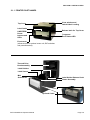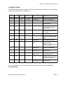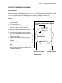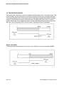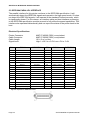
1
Operator
Service Manual
For printer model:
MB400i
D508
/ D512
/ MB410i
PN: 9001177B
9001193
www.satoamerica.com
SATO America, Inc.
10350A Nations Ford Road
Charlotte, NC 28273
Main Phone: (704) 644.1650
Technical Support: (704) 644.1660
Technical Support Fax: (704) 644.1661
E-Mail: [email protected]
[email protected]
www.satoamerica.com
Copyright 2008 SATO America, Inc. All rights reserved
WARNING
THE EQUIPMENT REFERENCED IN THIS DOCUMENT COMPLIES WITH THE REQUIREMENTS IN PART 15 OF FCC
RULES FOR A CLASS B COMPUTING DEVICE. OPERATION OF THIS EQUIPMENT IN A RESIDENTIAL AREA MAY
CAUSE UNACCEPTABLE INTERFERENCE TO RADIO AND TV RECEPTION.
PN: 9001177B
TABLE OF CONTENTS
OVERVIEW
1.1 Introduction .......................................................................................................... 1-2
INSTALLATION
Safety Precautions..................................................................................................... 2-2
2.1 Unpacking............................................................................................................. 2-4
2.1.1 Printer Part Names........................................................................................... 2-5
2.1.1 SETTING UP THE PRINTER ............................................................................. 2-6
2.2 Loading Media..................................................................................................... 2-7
2.3 Label Sensing....................................................................................................... 2-9
CONFIGURATION AND OPERATION
3.1 Operating PANEL................................................................................................. 3-1
3.2 THE REAR PANEL ............................................................................................... 3-2
3.3 THE CONFIGURATION PANEL ........................................................................... 3-3
Switch 4: Unused ....................................................................................................... 3-4
Switch 5: Head Check................................................................................................ 3-5
Switch 6: VR1 Potentiometer Adjustment mode..................................................... 3-5
3.4 Error Codes .......................................................................................................... 3-7
3.5 Offsets................................................................................................................... 3-8
3.6 Potentiometer Adjustments ................................................................................ 3-9
3.6 Potentiometer Adjustments (Cont’d) ................................................................. 3-10
3.7 DATA Dump Diagnostic Label ............................................................................ 3-11
3.8 Printing Test Labels............................................................................................. 3-12
3.9 Printing Factory/Service Test Prints .................................................................. 3-13
CLEANING AND MAINTENANCE
4.1 Introduction .......................................................................................................... 4-1
4.2 Adjusting the Print Quality.................................................................................. 4-1
4.3 CLEANING THE PRINT HEAD, PLATEN AND ROLLERS.................................. 4-2
4.4 Releasing/Replacing the Print Head ................................................................. 4-4
4.4 Cleaning the Sensor ........................................................................................... 4-5
INTERFACE SPECIFICATIONS
5.1 Interface types...................................................................................................... 5-1
5.2 The Receive Buffer .............................................................................................. 5-2
5.3 IEEE1284 Parallel Interface ................................................................................. 5-4
5.4 RS-232C Interface ................................................................................................ 5-5
5.4.1 RS-232C Interface Signals ............................................................................... 5-6
5.5 Universal Serial Bus Interface ............................................................................ 5-7
i
5.6 Local Area Network Interface..............................................................................5-7
5.7 WIRELESS LAN INTERFACE (802.11 b/g)..........................................................5-8
TROUBLESHOOTING
6.1 Initial Checklist .....................................................................................................6-1
6.2 Checking the IEEE1284 Parallel Interface..........................................................6-1
6.3 Error Signals.........................................................................................................6-5
6.3 Checking the 802.11G Wireless Interface ..........................................................6-6
SATO CONTACTS
SATO Group of companies .......................................................................................7-2
ii
Section 1: Introduction
OVERVIEW
1
Thank you for your investment in this SATO printer product.
This Operator’s Manual contains basic information about the installation, setup,
configuration, operation and maintenance of the printer.
A total of seven topics are covered herein, and they are organized as follows:
Section 1: Introduction
Section 2: Installation
Section 3: Configuration and Operation
Section 4: Cleaning and Maintenance
Section 5: Interface Specifications
Section 6: Troubleshooting
It is recommended that you become familiar with each section before installing and maintaining
the printer. Refer to the Table Of Contents at the front of this manual to search for the relevant
information needed. All page numbers in this manual consist of a section number followed by the
page number within the stated section.
Note:
All information herein was correct and current at the time of publication. The contents of this document are subject to revision and change without prior notification to users. To obtain the most
current version of this document, refer to the SATO America website at www.satoamerica.com.
SATO D508/D512 Operator Manual
Page 1-1
Section 1: Introduction
1.1 INTRODUCTION
The SATO D508/D512 Printer Operator Manual provides information for installing and
maintaining D508/D512 Direct Thermal printers. It is recommended that you become familiar with
each section in this manual before installing and maintaining the printer.
The major difference in the D508 and the D512 printers is the resolution of the print head. The
D508 with its 203 dpi head provides an economical labeling solution for most applications. The
D512's higher 305 dpi resolution provides greater detail for graphics and small point size text.
The D5 Series printers use a subset of the standard SATO Command Language. The D508 and
D512 share the same command set, the only differences are the allowable values representing
the print positions on the label. These values are specified in "dots" and will vary depending upon
the resolution of the printer and the amount of memory available for imaging the label. The allowable range for each printer is specified in a table for those command codes. In addition, users
can choose an interface—such as parallel (IEEE1284), serial (RS-232C), Ethernet (10/100BaseT), USB 1.1and Wireless LAN IEEE 802.11b.
The following general information is presented in this section:
•
General Printer Specifications
Page 1-2
SATO D508/D512 Operator Manual
Section 1: Introduction
1.1 GENERAL PRINTER SPECIFICATIONS
Attribute
PRINT
Print Method
CPU
Printer Command Language
Font / Symbologies
Font
Linear Barcode
2-D Barcode
Direct Thermal
32-bit RISC processor
SATO (SBPL) and PCL5e Subset
SATO Printer Command Language (for 203 dpi and 305 dpi):
U, S, M, WB, XS, XU, XM, XB, XL, OUTLINE, OCR-A, OCR-B,
WL, CG Times, CG Triumvirate
UPC-A, UPC-E, EAN-8, EAN13, Code 39, Code 93, Code 128,
Codabar, MSI, Bookland, Industrial 2/5, Interleaved 2/5, Matrix 2/5,
Postnet, UCC/EAN 128, RSS Composite Code
PDF417, Micro PDF417, Truncated PDF417, Maxicode, Data matrix,
QR Code
PCL5e Subset (Optional for 305 dpi only):
Font
CG Triumvirate Bold Condensed Bold, Univers Medium, Univers Bold,
Courier Regular, OCR-A, OCR-B, Roman Pillar Regular, Roman Pillar
Bold, Roman Pillar Italic, Roman Pillar Bold Italic (supports Universal
Font Scaling Technology Ver. 4.1)
Linear Barcode
UPC-A, UPC-E, EAN-8, EAN13, Code39, Cjode 93, Code 128, MSI,
Bookland, Indusstrial 2/5, Interleaved 2/5, Matrix 2/5, Postnet, UCC/
EAN 128
2-D Barcode
Font Memory
Print Head Resolution
Print Speed
PDF417, Maxicode
4 MB
8 dots per mm for 203 dpi | 12 dots per mm for 305 dpi
For D508: 6 ips (150 mm/second)
For D512: 4 ips (100 mm/second)
4.1” (104 mm) W by 15.7” (400 mm) L
Max. Print Area
SATO D508/D512 Operator Manual
Page 1-3
Section 1: Introduction
1.1 GENERAL SPECIFICATIONS (CONT’D)
Attribute
MEDIA
Media Type
Label Thickness
(Label + backing paper)
Label Form
Label Size (adhesive labels)
Roll and fanfold
0.0026” (0.6 mm*) - 0.007” (* 0.19 mm)
*Check with your dealer regarding conditions
for using thin 0.002” (06 mm) labels
Roll Label: Maximum outer diameter of 4.33” (110 mm) face out
Core Inner Diameter of 1.5” (40 mm)
Outer Diameter: 4.33” (110 mm)
Fan-fold label: Max. foldable height: 3.94” (100 mm) loaded externally)
Wind Orientation: Face-out
Width for all types:
1.1” (28 mm) - 4.65” (118 mm)
For continuous feed:
Length: 0.71” (18 mm) - 15.75” (400 mm)
For Cutter usage (optional):
Length: 1.1” (23 mm) - 15.75” (400 mm)
For Tear Off mode:
Length: 0.71” (18 mm) - 15.75” ( 400 mm)
SENSING
See-Through
Continuous Form
Eye Mark
For die-cut label with gap: Fixed, 0.25" (6.3 mm) from left label edge
Sensor not used
Reflective sensor (for use with Pre-printed eye marks)
*All specifications subject to change without notice.
Page 1-4
SATO D508/D512 Operator Manual
Section 1: Introduction
1.1 GENERAL SPECIFICATIONS (CONT’D)
Attributes
CONTROLS AND SIGNALS
On-Line LED
Power LED
Error LED
LED Display Panel
On/Off-Line Button
Label Feed Button
Power On/Off Button
Self Diagnostics
Green
Green
Red
7-Segment Single Character
Front Panel
Front Panel
Front Panel
Head check
Paper end
Cover open
Test print
POTENTIOMETER ADJUSTMENTS
Adjustment Potentiometers
VR1: Offset level (DIPSW6 = OFF)
VR1: Print darkness (DIPSW6 = ON)
VR2: Eye Mark
VR3: Gap sensor (to adjust the threshold)
VR4: Label pitch offset
DIP-SW -1,2,3 : Operation mode(Print mode/Download mode)
DIP-SW -4 : Reserved (constantly OFF)
DIP-SW -5 : Head check (ON-Enabled / OFF-Disabled)
DIP-SW -6 : VR1 function switch
(ON-Print darkness level / OFF-Offset)
DIP-SW -7 : DATA dump (ON-HEX dump print / OFF-Normal print)
DIP-SW -8 : Reserved (constantly OFF)
DIP switches
INTERFACE CONNECTIONS
Parallel (Option)
Serial (Option)
USB (Option)
LAN (Option)
RFID (Option)
Wireless LAN (Option)
IEEE1284
RS232C (up to 57.6K bps) Hardware Flow Control (Ready/Busy) Software Flow Control (X-On/X-Off)
Bi-directional Status
USB Specification Version 1.1
10/100 Base-T
TBA
802.11 b/g (internal)
*All specifications subject to change without notice.
SATO D508/D512 Operator Manual
Page 1-5
Section 1: Introduction
1.1 GENERAL SPECIFICATIONS (CONT’D)
Barcodes
SYMBOLOGIES
Supported 1D formats
(excluding customized barcode
addressing in firmware)
UPC-A/E
EAN-8/EAN-13
CODABAR
CODE39
CODE93
CODE128
UCC/EAN128
Interleaved 2 of 5
Industrial 2 of 5
Matrix 2of5
RSS Composite
MSI
POSTNET
Bookland
PDF 417
Micro PDF 417
Truncated PDF 417
Maxicode
Data Matrix
QR Code
1:2, 1:3, 2:5 User definable bar widths (depending on software)
4 to 600 dots (depending on software)
0°, 90°, 180° and 270° (depending on software)
Supported 2D formats
Ratios
Bar Height
Rotation
*All specifications subject to change without notice.
Physical Attributes
DIMENSIONS
Width
Depth
Height
Weight
POWER REQUIREMENTS
Voltage
Power Consumption
ENVIRONMENTAL
Operating
Storage
REGULATORY APPROVALS
Safety
EMC/EMS
SATO D508/D512 Operator Manual
7.8 in. (198 mm)
9.1 in. (230 mm)
6.6 in. (167 mm)
5.5 lbs (2.5 Kg) excluding AC adaptor
USA: AC 115 V (+/- 10 %)
50/60 Hz (+/-1%)
67W nominal
32° to 95°F (0° to 35°C),
30 to 80% RH, non-condensing
23° to 140°F (-5° to 60°C),
30-90% RH, non-condensing
USA : UL(UL60950-1)
CANADA : C-UL(CSA C22.2 No.60950-1-3)
USA : FCC15B (ClassB)
Page 1-6
Section 1: Introduction
Optional Accessories
220V Power Supply
Internal Cutter
IEEE1284 Interface
Serial Interface
LAN Interface
USB Interface
RFID
Wireless LAN Interface
Auto-switching
User or factory installed Internal option allowing
labels to be cut at specified intervals.
Parallel interface. Factory or User installable
High Speed RS232 Interface option, 9600 bps to
57.6 Kbps. Factory or User installable.
TCP/IP Protocol Interface option. Factory or User
installable.
Universal Serial Bus Interface option. Factory or
User installable.
To be announced
802.11 b/g
*All specifications subject to change without notice.
SATO D508/D512 Operator Manual
Page 1-7
Section 1: Introduction
SATO D508/D512 Operator Manual
Page 1-8
SECTION 2: INSTALLATION
INSTALLATION
2
This section assists you in unpacking the printer from the shipping container. You will also be
guided through a familiarization tour of the main parts and controls. The following information is
provided herein:
• Safety Precautions
• Unpacking and Parts Identification
• Loading Media
• Adjusting the Sensor
SATO D508/D512 Operator Manual
Page 2-1
SECTION 2: INSTALLATION
SAFETY PRECAUTIONS
SAFETY PRECAUTIONS
Please read the following information carefully before
installing and using the printer
THE CAUTION SYMBOL
Whenever the triangular Caution logo appears in this manual, pay special attention to the warning(s) cited
below it. Failure to abide by the warnings may result in injury or damage to property.
PRINTER PLACEMENT TIPS
• Place the printer on a solid, stable, horizontal surface that is not subject to strong vibrations from adjacent mechanical devices.
• Avoid shaky or slanting tables, or platforms that are
liable to collapse under a heavy weight. If the printer
is dropped or damaged, immediately turn off the
power, pull out the power plug and contact a service
center. In this case, continued use of the printer may
cause a fire or electric shocks.
• Avoid installing the printer in direct sunlight, or in
dusty, very hot or slippery areas. Also avoid placement in damp, unventilated or humid areas. If condensation forms, immediately turn off the power, and
do not use the printer until the condensation disappears. Otherwise the moisture may cause electric
shocks.
• Avoid placing the printer near large high-current
equipment, as such equipment can cause spikes or
undervoltages in the power supply.
• Do not leave containers of water or chemicals
around the printer. If any liquid is spilled onto
the printer, immediately turn off the power, pull
out the power cable from the AC outlet, and
contact a sales outlet, dealer, or service center.
In this case, continued use of the printer may
cause fires or electric shocks.
• Do not move the printer with any paper loaded.
The stack of paper may fall off, causing trips
and accidents.
• When laying the printer down, be careful not to
catch your foot or fingers under it.
• When moving the printer, be sure to pull out the
power cable from the AC outlet, and check that
any other external interface cables have been
disconnected. Otherwise, the connected cables
may be damaged, or may cause trips and falls,
in addition to or a fire or electric shocks.
ELECTRICAL PRECAUTIONS
• Do not damage, break, or process the power cable.
Hanging heavy objects on it, heating or pulling it may
damage the power cable and cause fires or electric
shocks.
• When the power cable is damaged (cable conductors
are exposed or cut, etc.), contact a sales outlet,
dealer, or service center. In this case, continued use
of the printer may cause fires or electric shocks.
• Do not process, forcibly bend, twist, or pull the power
cable. Continued use of such a cable may cause
fires or electric shocks.
• If the printer emits any smoke or peculiar odors at
any time, turn it OFF and prevent further usage until
you have contacted a qualified service personnel.
• Do not use any other voltage except the specified
power voltage for the printer that matches your
domestic power supply. Otherwise, it may cause fires
or electric shocks.
Page 2-2
• Do not operate the power switch or handle the
power cable with a wet hand.
• Do not insert or drop anything metallic or flammable into the openings of the printer (the cable
outlet or mounting hole of the memory cartridge). Otherwise, immediately turn off the
power, pull out the power cable, and contact a
sales outlet, dealer, or service center. In this
case, continued use of the printer may cause
fires or electric shocks.
• To reduce electrical risks, be sure to connect
the printer to ground before use. Also, try not to
share the printer’s AC outlet with other electrical equipment, especially those that draw high
amounts of current or cause electrical interference.
SATO D508/D512 Operator Manual
SECTION 2: INSTALLATION
GENERAL PRECAUTIONS
• When using head cleaning liquid, note that it is flammable. Never heat it or throw it into a fire. Keep it out
of children’s reach to avoid accidental consumption.
Should this occur, consult a doctor immediately.
• When opening/closing the cover, beware of getting
your fingers caught. Also, hold the opening/closing
cover well so that it will not slip and fall onto the
hand.
• After printing, the print head remains hot. When
replacing paper or cleaning the printer immediately
after printing, be careful not to burn yourself.
• Touching even the edge of the printer head may
cause injuries. When replacing paper or cleaning the
printer, be careful not to hurt yourself.
• Do not disassemble or perform modifications to
the printer, as this renders the product unsafe.
For maintenance, troubleshooting and repairs,
consult a sales outlet, dealer, or service center
for help, instead of attempting to perform this
yourself. Renewable annual service contracts
are available.
• When maintaining or cleaning the printer,
always disconnect the power cable for safety.
• Do not insert your hand or other objects into the
cutter.
• When loading roll paper, be careful not to catch
your fingers between the paper and the feeder.
• If the printer will not be used for extended periods of
time, disconnect the power cable for safety.
• Be careful not to hurt yourself when detaching
the back cover of the fanfold through the hole
and attaching it.
• When releasing and locking down the printer head,
be careful not to catch any other foreign matter in it
except label paper.
• The simplified cutter (if applicable to the printer)
is structured as a blade. Be careful not to cut
yourself.
This is a piece of Class B information technology equipment based on the standards of the Voluntary Control
Council for Interference by Information Technology Equipment (VCCI). Although this equipment is for use in
home environment, if it is used close to a radio or television set, it may cause poor reception. Handle it
properly in accordance with the content from the instruction manual.
SATO D508/D512 Operator Manual
Page 2-3
SECTION 2: INSTALLATION
2.1 UNPACKING
When unpacking the printer, take note of the following:
1 The box should stay right-side up.
Lift the printer out of the box carefully.
4 If the printer has been stored in the
cold, allow it to reach room
temperature before turning it on.
2 Remove the plastic covering from the
printer.
5 Set the printer on a solid, flat surface.
Inspect the shipping container and
printer for any sign of damage that
may have occurred during shipping.
3 Remove the accessory items from their
protective containers.
Note:
The following parts shown here are representative only. Due to regional requirements and our policy of
continual improvement, your printer may not be packed with the exact parts as shown here, but the
unpacking steps are similar.
Printer
AC adaptor and cable
User documentation and software
package (where applicable)
Page 2-4
SATO D508/D512 Operator Manual
SECTION 2: INSTALLATION
2.1.1 PRINTER PART NAMES
Clear window and
fanfold-label Loading
Top Cover
Label Outlet
Release latch for Top Cover
LINE/FEED/
Power
buttons and
LEDs
7-segment
Error Status LED
Front cover
(allows access to optional cutter unit, DIP switches
and potentiometers)
Thermal Print
Head assembly
Label Holders
Label Sensor
Mini
Screwdriver
Label Holder Release Knob
Platen Assembly
Optional Cutter
SATO D508/D512 Operator Manual
Page 2-5
SECTION 2: INSTALLATION
2.1.1 SETTING UP THE PRINTER
Consider the following when setting up the printer:
Locate a solid flat surface with adequate room to set the printer. Make sure the AC
adaptor can be located so that the AC power cable can be attached to the printer and
an AC power outlet. The location should be near the host or computer terminal. The
maximum distance recommended is:
- 10 feet for a Parallel interface cable. Make sure it meets IEEE1284 specifications
- 18 feet for the optional Serial RS232 Interface
- 10 feet for the optional USB interface without hub
- the optional 10baseT Ethernet Interface depends upon the LAN cabling
- Up to 100m for the Wireless LAN, depending on structural conditions
Follow these steps to set up your printer:
1. Make sure the power switch on the Operator
Panel is in the OFF (0) position and place the
AC adaptor in a safe and secure location.
2. Connect the Input Power connector to the
printer. This connector is buttoned and must
be turned approximately 3/4 turn clockwise to
secure it to the printer.
3. Connect the AC Power Cable to an AC Outlet
supply of an appropriate voltage.
4. Connect the interface cable to the host system.
If you are using the Parallel Port connection, a
parallel IEEE1284 interface cable must be
used to realize the high data transfer rate of
the printer's parallel port. If another interface is
installed, the appropriate cable should be
used.
5. Load the label media following the instructions
in this section.
6. Configure the printer for label width and operating mode using the instructions in this section.
7. Press the printer power button to the ON (I) position.
8. Print a test label to verify the printer is set up and operating correctly.
Page 2-6
SATO D508/D512 Operator Manual
SECTION 2: INSTALLATION
2.2 LOADING MEDIA
The SATO D508 / D512 printer can print to direct thermal die-cut labels, tags or continuous media.
The media supply can be either in Roll or Fanfold format.
Roll Media
Roll media should be between 0.98" (25 mm) and 4.3" (110 mm) in width and wound face-out on a
core with a minimum internal diameter of 1.6" (40 mm).
1.
Make sure the printer is turned OFF.
2. Open the Top Cover by pressing on cover
release points located on the right-hand side
of the printer. This releases the Top Cover and
allows it to swing upward on the rear mounted
hinge points.
3. With the Top Cover in the upright position,
press the Paper Guide Release while adjusting the Paper Guides until they allow a media
roll to fit between them. A millimeter scale is
molded into the case to provide a guide when
making the adjustment. The Paper Guides are
center justified and interact with each other so
that each moves an equal distance.
Paper
Sensor
Cover/Print Head
Release Latch
Roll Holders
4. Make sure the Roll Holders are in the released
position. If they are not, lift up on each one and
they will snap to the open position.
Millimeter
scale
5. Unwind approximately 12" of label material
from the roll. The labels should be wound
face-out (printing side to the outside of the
roll). Drop the roll in-between the Paper
Guides so that the labels come off the top of
the roll. The Paper Guides will automatically
position the Roll Holders to suspend the roll.
SATO D508/D512 Operator Manual
Paper Guide
Release
Label path
Page 2-7
SECTION 2: INSTALLATION
6. Route the label material through the Paper
Sensor Assembly and over the Platen. Note
that the Sensor is part of the left Label Roll
Guide so that the Paper Sensor is always
positioned in the same location relative to
the left edge of the label.
Platen
7. Close the Top Cover.
8. Press the LINE button so that the printer is
in the OFF LINE mode and then press the
FEED button. The label should advance to
the next index (label gap) position.
Paper Sensor Paper Guide
Fanfold media
1. Place the fanfold media behind the printer
with the printing surface up.
Fanfold-label Loading slot
2. Open the Top Cover by pressing on the cover
release latch located on the right-hand side
of the printer. This releases the cover and
allows it to swing upward on the rear
mounted hinge points.
3. Carefully pull up the Fanfold-label Loading
Slot from the back of the Top Cover.
4. With the Top Cover in the upright position,
press the Paper Guide Release while adjusting the Paper Guides until they allow a media
to fit between them. A millimeter scale is
molded into the case to provide a guide when
making the adjustment. The Paper Guides
are center-justified and interact with each
other so that each moves an equal distance
apart from each other.
5. Route the label material through the Sensor
Assembly and over the Platen.
Page 2-8
Pull up
the
loading
slot
Pull
open
the Top
Cover
Load
the
fanfold
paper
SATO D508/D512 Operator Manual
SECTION 2: INSTALLATION
6. Close the Top Cover.
7. After loading the label media, it is
recommended that you run a Test
Print to make sure the labels are
correctly loaded and printed.
Roll-label path
Fanfold-label path
Overview of the fanfold-paper loading path
2.3 LABEL SENSING
The SATO D508 / D512 printer uses label Gap (see-through) sensing. The Sensor Assembly is
located on the left edge of the media and is automatically positioned by the Paper Guides.
SATO D508/D512 Operator Manual
Page 2-9
SECTION 2: INSTALLATION
This page is left blank intentionally
Page 2-10
SATO D508/D512 Operator Manual
Section 3: Configuration and Operation
CONFIGURATION AND OPERATION
3
Before using the printer, it is best to read this manual thoroughly first. Otherwise, you may disturb
default settings around which the instructional procedures in this manual are based upon.
3.1 OPERATING PANEL
The Operator Panel consists of three LED indicators and three switches.
POWER
The green LED lights up when the printer is ON.
ERROR
The red LED lights up when there is a system fault
such as an unlatched print head.
ON LINE
The green LED lights up when the printer is ON LINE
and ready to receive data. The ON LINE button
takes the printer ON LINE or OFF LINE.
LINE Button
If the ON LINE LED is lit, pressing it will take the printer
OFF LINE. Pressing the button again then takes the
printer back ON LINE. When ON LINE, the printer
is ready to receive data from the host. When OFF LINE,
the printer will not print or accept data from the host.
While the printer is printing, press this button to suspend the
printing. To resume printing, press this button again.
FEED BUTTON
Press this button to eject one label in OFF LINE mode.
Hold this button down while power is applied, to print a printer
status label.
POWER SWITCH
A two position switch for turning the printer ON (I) or OFF (0).
SATO D508/D512 Operator Manual
Page 3-1
Section 3: Configuration and Operation
3.2 THE REAR PANEL
All of the printer cable connectors are located on the Rear Panel, as follows.
Fanfold-label Loading Slot
Remove this panel to route fanfold paper into the printer
IEEE1284
Parallel
Interface
Connector
Page 3-2
Power
Connector
for DC power
input from the
supplied AC
Adapter
SATO D508/D512 Operator Manual
Section 3: Configuration and Operation
3.3 THE CONFIGURATION PANEL
The Configuration Panel is accessible when you lift up the top cover.
The panel consists of an eight-position DIP switch, four adjustment potentiometers and a sevensegment LED Error Status display. Receptacles for connecting the optional Cutter (factory
installed) are also located on this panel.
Change and fine-tune your printer settings as required by using the mini-screw driver to turn the
potentiometers clockwise/anti-clockwise until you have the optimal adjustment position.
Do not touch VR2 and VR3. They are reserved for professional adjustments and for a trained
service person only.
VR4
Label Pitch
Offset
VR1
Offset or
Darkness
DIP switch for
Configuration
VR2
VR3
Paper handling
Reserved
Head Check
VR1 adjust
DATA Dump
Reserved
Error
Status
LED
DIP SWITCH SETTINGS
This is an eight-position switch used for setting the operating conditions of the printer. Switches 1
to 3 act as control for both paper handling and the loading of programs or fonts into the printer.
SATO D508/D512 Operator Manual
Page 3-3
Section 3: Configuration and Operation
Switches 1–3: Paper Handling settings
These three switches select the method used for
controlling paper handling:
Continuous mode - (default mode) Does not
use the sensor for paper indexing. The paper
movement will stop after all the label data has
been printed.
Tear Off mode - Paper is fed out to the cut/tear
off position after printing is complete. Before the
next label is printed, the paper is pulled back in
to the first print line position.
DSW1 DSW2 DSW3
Mode
Off
Off
Off
Continuous
On
Off
Off
Tear Off
Off
On
Off
Cutter
On
Off
On
Reserved
Off
On
On
Load Font
Configuration Switch
ON
OFF
1
2
3
4
5
6
7
8
Cutter mode - Enables the Cutter option if
installed.
3.3 DIP SWITCH SETTINGS (CONT’D)
Switches 1–3: Font/Graphic loading settings
Enables the loading of fonts and/or graphics into
printer memory for faster retrieval.
DSW1 DSW2 DSW3
Off
On
Mode
On
Load Font
Configuration Switch
ON
OFF
1
Switch 4: Unused
This switch is reserved for future use.
2
3
4
5
6
DSW4
Mode
Off
DT
-
Reserved
7
8
7
8
Configuration Switch
ON
OFF
1
Page 3-4
2
3
4
5
6
SATO D508/D512 Operator Manual
Section 3: Configuration and Operation
Switch 5: Head Check
Enables or Disables the printer function that checks
the print head automatically.
DSW5
Mode
Off
Disabled
On
Enabled
Configuration Switch
ON
OFF
1
Switch 6: VR1 Potentiometer Adjustment mode
Selects the function adjusted by VR1. When placed
in the Off position, VR1 will adjust the media tear-off
/ cut (backfeed distance) offset value over a range
of +/- 3.75 mm. When placed in the On position,
VR1 will adjust the print darkness range.
2
3
4
5
6
DSW6
Mode
Off
Media Tear-off
On
Print Darkness
7
8
7
8
7
8
Configuration Switch
ON
OFF
1
2
3
4
5
6
3.3 DIP SWITCH SETTINGS (CONT’D)
Switch 7: DATA Dump
When ON, the printer will print out the hex value for
each character received. When OFF, the printer will
accept and process the data stream in a normal
fashion.
DSW7
Mode
Off
DISABLED
On
ENABLED
Configuration Switch
ON
OFF
1
SATO D508/D512 Operator Manual
2
3
4
5
6
Page 3-5
Section 3: Configuration and Operation
Switch 8: Unused
This switch is reserved for future use.
DSW8
Mode
-
-
-
-
Configuration Switch
ON
OFF
1
Page 3-6
2
3
4
5
6
7
8
SATO D508/D512 Operator Manual
Section 3: Configuration and Operation
3.4 ERROR CODES
The ERROR display is a seven-segment LED array that provides information on error conditions
detected by the printer. The conditions are:
0
ON
1 Beep
1
Flash Memory error
Consult your SATO dealer
Not Assigned
2
ON
1 Beep
Machine Error
Consult your SATO dealer
3
ON
1 Beep
EEPROM Error
Replace EEPROM
4
ON
1 Beep
Electrical Head error
Replace Print Head or consult
your SATO dealer
5
Blink
3 Beeps
Head Not Latched
Latch Print Head securely and
make sure the Top Cover is
closed properly
6
Blink
3 Beeps
Out of Paper
1) Replenish paper supply
2) Route paper through sensor
correctly
7
Blink
3 Beeps
Sensor error
1) Adjust sensor level
8
Blink
3 Beeps
Cutter error
Connect cutter (optional item)
properly or consult your SATO
dealer
Program Error
Resend data to the printer
Receive Buffer Overflow
1) Restart the printer and retry
8.
ON
A
ON
ON
1 Beep
2) Modify host SW
3) Select correct communication
protocol settings
b
ON
1 Beep
Parity error
(Serial I/F only)
Correct the Parity Settings or
consult your SATO dealer
c
ON
1 Beep
Framing Error
(Serial I/F only)
Check and correct the data bit
setting and retry
d
ON
1 Beep
Overrun Error
(Serial I/F only)
Check and correct the flow control settings and retry
E
ON
1 Beep
LAN Time Out Error
Check the Interface Card and all
associated connections to/from
it. Replace if necessary
3 Beeps
Font/graphic Data
Error (Serial I/F only)
Recheck and correct the data
stream and retry
F
For more information on the cause and troubleshooting of printer errors, see Section 6.
Troubleshooting.
SATO D508/D512 Operator Manual
Page 3-7
Section 3: Configuration and Operation
3.5 OFFSETS
There are two offset settings stored in the printer; one for the Cut mode and one for the Tear-Off
mode.
These two offsets can be set independently and will remain in the printer until a new command is
received changing the setting or until power is turned off.
The default settings can be determined by printing a User Test Label.
The following should be used as starting points for establishing the three Offset values:
Mode
Length of Offset (mm) Length of Offset (in) Print head resolution
CUTTER
17.9
0.70
143/215
TEAR-OFF
29.2
1.15
234/350
Page 3-8
SATO D508/D512 Operator Manual
Section 3: Configuration and Operation
3.6 POTENTIOMETER ADJUSTMENTS
PITCH OFFSET
This can be done using the VR4 potentiometer on the Configuration Panel. This potentiometer is
set at the factory so that it has a range of +/-3.75 mm. The midpoint setting should have no effect
on the label pitch. Turning the potentiometer all the way clockwise should move the print position
3.75 mm upwards towards the leading edge of the label. Turning the it all the way
counterclockwise should move the print position down 3.75mm away from the leading edge of
the label.
1.
Place DSW6 on the Configuration Switch in
the OFF position.
Must be moved with Minus (-)
Offset to print on leading edge of
label
2. Turn the power OFF.
3. While pressing the FEED button on the
Operator Panel, turn the power ON.
ABCDEFG
4. When you hear one beep from the printer,
release the FEED button.
6. Adjust potentiometer VR4 until the first
print position is at the desired location on
the label.
7. Press the FEED button to stop printing.
ABCDEFG
label movement direction
5. Press the LINE button to begin printing
large Test Labels (press the FEED button
if you are using labels smaller than 4.1"
(104 mm) in width).
Original First Line
Print Position
ABCDEFG
Note:
Adjusting the Label Pitch with VR4 will
affect the stop position of the label and the
cut/tear-off positions.
Moved with
Positive (+) Offset
to print on trailing
edge of label
SATO D508/D512 Operator Manual
Leading Edge of
Label as detected
by the sensor
Page 3-9
Section 3: Configuration and Operation
3.6 POTENTIOMETER ADJUSTMENTS (CONT’D)
Print Darkness
A fine adjustment for PRINT DARKNESS can be made using potentiometer VR1 on the Front
Operator Panel. It provides a continuous range of adjustment, allowing you to make precise
changes. Turning VR1 clockwise will make the print darker, and counterclockwise will make it
lighter.
1. Place DSW6 on the Configuration Switch in the ON position.
2. Turn the Power Switch OFF.
3. While pressing the FEED button on the Operator Panel, turn the Power Switch ON.
4. When you hear one beep from the printer, release the FEED button.
5. Press the LINE button to begin printing large Test Labels (press the FEED button if you are
using labels smaller than 4.1" (104 mm) in width).
6. Adjust potentiometer VR1 until the desired print darkness is obtained.
7. Press the FEED button to stop the printing.
Adjustment of the Print Darkness using VR1 will affect the darkness in all the<ESC>#E
command code ranges; that is, if the print darkness is adjusted with VR1 for lighter print, the
darkness will be lighter in all the Print Darkness ranges selected by the command code.
Page 3-10
SATO D508/D512 Operator Manual
Section 3: Configuration and Operation
3.7 DATA DUMP DIAGNOSTIC LABEL
The contents of the printer buffer can be examined using the DATA Dump mode. This printout
labels each line of the received data in the left hand column, the data in the middle column
followed by the same data in ASCII format in the right-hand column.
1. Turn the printer OFF.
2. Place DSW7 on the configuration Switch in the ON position.
3. Turn the printer ON.
4. Transmit data to the printer.
5. The data received is printed on the label.
6. Place DSW7 in the OFF position.
7. Turn the printer OFF and then back ON to place it back in the normal print mode.
Note:
Depending on the version of your printer’s onboard software, the appearance of your test
printout may be different from that shown here.
SATO D508/D512 Operator Manual
Page 3-11
Section 3: Configuration and Operation
3.8 PRINTING TEST LABELS
1. The User Test Label prints the current default settings of the printer.
2. Press the FEED button while turning the power ON.
3. When the printer beeps, release the FEED button.
4. To print a large (4" wide) test label, press the LINE button. To print a small (2" wide) test label,
press the FEED button.
5. The printer will continuously print the USER TEST LABEL until the FEED button is pressed. If
the FEED button is pressed another time, printing will resume.
6. To remove the printer from the Test Label mode, power the printer OFF.
Note:
Depending on the version of your printer’s onboard software, the appearance of your test
printout may be different from that shown here.
Page 3-12
SATO D508/D512 Operator Manual
Section 3: Configuration and Operation
3.9 PRINTING FACTORY/SERVICE TEST PRINTS
The Factory/Service Test Label prints the internal operating parameters of the printer.
1. Release the print head. (see “Releasing/Replacing the Print Head” on page 4-3).
2. Press the LINE and FEED buttons while turning the printer ON.
3. When the printer beeps, release the LINE and FEED buttons. The printer will then beep 3
times indicating it is in the Factory/Service Print Test mode.
4. Relatch the Print Head.
5. Press the LINE button to print a large (4" wide") Factory/Service Test Label. Press the FEED
button to print a small (2" wide) Factory/Service Test Label.
6. The printer will begin printing a series of test labels, the first containing the operational
parameters of the printer followed by one containing the internal printer settings. These two
label formats will alternate until the FEED button is pressed, suspending the print operation. If
the FEED button is pressed again, the printing will resume.
To remove the printer from the Factory/Service Print Test mode, remove power by placing the
POWER switch in the OFF position.
SATO D508/D512 Operator Manual
Page 3-13
Section 3: Configuration and Operation
SATO D508/D512 Operator Manual
Page 3-14
SECTION 4: CLEANING AND MAINTENANCE
CLEANING AND MAINTENANCE
4
4.1 INTRODUCTION
This section provides information on user maintenance for the SATO D508/D512 printers. This
section contains the following information.
•
•
•
•
Adjusting the Print Quality
Cleaning the Print Head, Platen and Rollers
Replacing the Print Head
Replacing the Fuse
4.2 ADJUSTING THE PRINT QUALITY
The SATO D508 / D512 printer is equipped with two different methods of adjusting the quality of
the print—print darkness and print speed.
When adjusting the printer for optimum print quality, a barcode verifier system is highly
recommended for evaluating the printouts. The human eye is a poor judge of the relative widths
of the bars in a symbol, a characteristic that is extremely important for good bar code quality.
Print Darkness
This adjustment allows the user to control (within a specified range) the amount of power that is
used to activate the print head heating elements. It is important to find a proper print darkness
level based on your particular label. The printed images should not be too light nor should the
edges of text or graphics be smudged. Instead, the edges of each image should be crisp and well
defined.
Once the range has been selected, the PRINT Potentiometer (VR1) on the front panel can be
used to make finer adjustments. It provides a continuous range of adjustment, allowing you to
make precise changes. Use a small cross-point screwdriver, turning clockwise for darker print
and counterclockwise for lighter print. DSW6 has to be ON in order for to adjust the print darkness via
the VR1 potentiometer. See page 3-3 for instructions on performing potentiometer adjustments.
Note:
Adjustment of the Print Darkness using VR1 will affect the darkness in all the<ESC>#E command code
ranges. That is, if the print darkness is adjusted with VR1 for lighter print, the darkness will be lighter in all
the Print Darkness ranges selected by the command code.
SATO D508/D512 Operator Manual
Page 4-1
SECTION 4: CLEANING AND MAINTENANCE
Print Speed
The other method of controlling print quality is by controlling the speed at which the label is
printed. It is especially critical when printing "ladder" bar codes (bar codes printed with the bars
parallel to the print line). When printing a "ladder" bar code, it is important to allow the head to
cool sufficiently before stepping to the next position. If it does not have sufficient time to cool, the
bar will be "smeared" on the trailing edge.
This adjustment is made only on an individual label basis using the <ESC> CS command. For
more details on this command, see the Programming Reference.
4.3 CLEANING THE PRINT HEAD, PLATEN AND ROLLERS
Cleaning the Print Head
1. Before starting, get ready an approved cleaning kit from
your SATO dealer or the kit supplied with the printer.
Make sure the printer is OFF, and remove the power
cable.
2. Lift up the Top Cover and locate the Print Head Assembly which is mounted under the cover.
3. Apply Thermal Print Head Cleaner to a cotton swab.
4. The Print Head faces downward along the front edge of
the assembly. Pass the end of the dampened swab
along the entire width of the Print Head.
5. Check for any black coloring or adhesive on the swab
after cleaning.
6. Repeat if necessary until the swab is clean after it is
passed over the head.
7. The head should be cleaned at least every time the
label roll is changed, and more often in harsh environments.
Clearning Stubborn Debris on the Print Head
1. If certain stains on the print head cannot be removed
easily with cotton swabs dabbed in cleaning solution,
obtain cleaning sheets designed for cleaning print
heads (for such supplies, contact your SATO dealer)
2. Load the cleaning sheet with the rough side facing the
print head. Follow any other instructions or precautions
printed on any leaflet that may accompany the cleaning
sheet.
3. With the printer turned OFF, and the Top Cover closed,
slowly pull the cleaning sheet outwards. Repeat the process until the print head is clean.
Page 4-2
SATO D508/D512 Operator Manual
SECTION 4: CLEANING AND MAINTENANCE
4.3 CLEANING THE PRINT HEAD, PLATEN AND ROLLERS (CONT’D)
Cleaning the Platen and Paper Roller
1. Before starting, get ready an approved cleaning kit from
your SATO dealer or the kit supplied with the printer.
Make sure the printer is OFF, and remove the power
cable.
2. Lift up the Top Cover.
3. The platen roller is the black rubber roller near the front
panel. The print rollers are located at the print head
assembly, near the fanfold-label loading window.
4. Wet some cotton swabs with cleaning solution. While
rotating the platen roller with your fingers, clean the
entire length of the roller using one or more cotton
swabs. The roller should be cleaned of any label or
adhesive residue.
5. Repeat the whole cleaning process if necessary. The
platen and rollers should be cleaned whenever foreign
matter such as dust or adhesive is present.
Paper
Roller
SATO D508/D512 Operator Manual
Page 4-3
SECTION 4: CLEANING AND MAINTENANCE
4.4 RELEASING/REPLACING THE PRINT HEAD
The print head on the printer is a user-replaceable item. If it becomes damaged for any reason, it
can be easily removed and replaced. Contact your local SATO representative for information on
obtaining a new print head. You will also need a No. 2 Phillips screwdriver (a magnetic tip is
helpful) for the replacement procedure.
1. Make sure the printer is OFF, and remove the power cable.
2. Lift up the Top Cover.
3. Locate the small center tab above the print head. Press and
hold down this tab. At the same time, pull the whole print
head below it, downwards. If necessary, use the two hooks
at the sides of the print head for leverage.
Hook
4. After pulling the print head downwards, press its bottom
portion so that it tilts inwards on the two aluminum pivots at
the sides of the assembly.
5. Now lift the print head upwards and outwards, so that it is
no longer restrained by the metal pivots. The cable connector at the rear of the print head is now exposed.
6. Disconnect the connecting cable from the print head connectors and set the print head aside.
7. Carefully attach a replacement print head to the cable connector. The connectors are keyed so that they can only be
inserted in the correct orientation.
Connect
Piv
Key
Note:
While handling the print head, be careful not to scratch the
printing surface of the print head. Scratching the surface
will cause permanent and irreparable damage that is not
covered by the warranty!
8. Reinsert the print head into the printer, making sure that the
metal slots at the sides of the print head fit back over the
aluminum pivots on the printer.
9. Press and hold down the center tab which was previously
used to release the print head. Push the print head
upwards so that it snaps into place.
10. Release the center tab and close the Top Cover. Proceed to
perform a test print to ensure that the print head is connected properly.
Page 4-4
Key
pri
slot for
pivot
SATO D508/D512 Operator Manual
SECTION 4: CLEANING AND MAINTENANCE
4.4 CLEANING THE SENSOR
The gap sensor is used to control the positioning of the label. It is a transmissive see-thru sensor
that detects the edge of the label by looking through the backing paper which is translucent and
detecting the presence of the opaque label.
So when dust, dirt or other foreign matter interferes with the light path of the sensor, erratic label
positioning occurs. The sensor should thus be cleaned regularly, after every two rolls of labels.
1. Turn the printer OFF and remove the power cable.
2. Open the Top Cover.
3. Locate the sensor located next to the yellow screwdriver, near the left-hand side label guide so that it
moves whenever the Label Guide are adjusted for different media widths.
4. Apply Thermal Print Head Cleaner to a cotton swab.
5. Use the cotton swab to clean any foreign matter from
the exposed surface of the sensor by inserting the cotton tip in the paper slot and briskly cleaning it with a
back and forth motion.
SATO D508/D512 Operator Manual
Page 4-5
SECTION 4: CLEANING AND MAINTENANCE
This page is left blank intentionally
Page 4-6
SATO D508/D512 Operator Manual
SECTION 5: INTERFACE SPECIFICATIONS
INTERFACE SPECIFICATIONS
5
5.1 INTERFACE TYPES
The SATO D508 / D512 printer can be ordered with any of the interfaces described in this
section.
The user can specify the desired interface at the time of placing an order. Thereafter, if the
user needs to change the interface, it is a simple matter of purchasing a suitable interface
card from a SATO dealer.
The following are the different types of interface boards available:
1)
RS232C Interface Board
2)
IEEE1284 Parallel Interface Board
4)
USB Interface Board
5) LAN Interface Board (standard 10Base-T/100Base-T interface with RJ-45
connector)
6) Wireless LAN (802.11 b/g)
For programmers and technical personnel to fully utilize the printer, the following
information is presented in this section:
• The Receive Buffer
• IEEE1284 Parallel Interface
• RS232C Serial Interface
General Specifications
Electrical Specifications
Pin Assignments
Ready/Busy Flow Control
X-On/X-Off Flow Control
• Universal Serial Bus (USB) Interface
• Local Area Network (LAN) Interface
• Wireless LAN Interface (802.11b/g)
SATO D508/D512 Operator Manual
Page 5-1
SECTION 5: INTERFACE SPECIFICATIONS
5.2 THE RECEIVE BUFFER
This printer has the ability to receive a data stream from the host in one of two ways. The
receive buffer may be configured to accept one print job at a time or multiple print jobs.
The single job print buffer is generally used by software programs that wish to maintain
control of the job print queue so that it can move a high priority job in front of ones of
lesser importance. The multiple job buffer, on the other hand prints all jobs in the order
they are received by the printer, and the order of printing cannot be changed.
Single Job Buffer
The printer receives and prints one job at a time. Each job must not exceed 2.95MB.
Page 5-2
SATO D508/D512 Operator Manual
SECTION 5: INTERFACE SPECIFICATIONS
5.2 THE RECEIVE BUFFER (CONT’D)
Multi Job Buffer
The printer is able to continuously receive print jobs, compiling and printing other jobs at the
same time. It acts much like a "print buffer" to maximize the performance of the host and the
printer.
When you are using the RS232 Serial interface, the Multi Job Buffer uses either the Ready/
Busy with DTR (pin 20) or X-On/X-Off flow control protocols. With an empty receiving
buffer, the status of DTR is "high" (or an X-On status if using X-On/X-Off), meaning the
printer is ready to receive data. When the receive buffer is holding 1.95MB of data (1MB
from being full), DTR will go "low" (or an X-Off is sent) indicating the printer can no longer
receive data. This condition is called "Buffer Near Full."
The receiving buffer will not be able to receive more data again until a "Buffer Available"
condition occurs. This takes place when the receiving buffer has emptied so that only 1MB
bytes of data are being held (1.95MB bytes from being full). At this time, DTR will go "high"
or an X-On is sent to tell the host that it can again receive data.
All printer error conditions (i.e., label out, Time-out Error, etc) will cause the printer to go
busy (DTR "low" or X-Off) until the problem is corrected and the printer is placed on-line.
The printer will also be busy if taken off-line from the front panel.
SATO D508/D512 Operator Manual
Page 5-3
SECTION 5: INTERFACE SPECIFICATIONS
5.3 IEEE1284 PARALLEL INTERFACE
The parallel interface for this printer conforms to the IEEE1284 specification. It will
automatically detect the IEEE1284 signals and operate in the high speed mode. If it does
not detect the IEEE1284 signals, it will operate in the standard Centronics mode, which
is significantly slower. For this reason, an interface cable and host interface conforming
to the IEEE1284 specification must be present to fully utilize the speed capabilities. This
interface also operates bidirectionally and can report the status of the printer back to the
host.
Electrical Specifications
Printer Connector
Cable Connector
Cable Length
Signal Level
AMP 57-40360 (DDK) or equivalent
AMP 57-30360 (DDK) or equivalent
10 ft. (3 m) or less
High = +2.4V to +5.0V Low = 0V to -0.4V
PIN
SIGNAL
DIRECTION
PIN
SIGNAL
DIRECTION
1
STROBE
To Printer
19
STROBE Return
Reference
2
DATA 1
To Printer
20
DATA 1 Return
Reference
3
DATA 2
To Printer
21
DATA 2 Return
Reference
4
DATA 3
To Printer
22
DATA 3 Return
Reference
5
DATA 4
To Printer
23
DATA 4 Return
Reference
6
DATA 5
To Printer
24
DATA 5 Return
Reference
7
DATA 6
To Printer
25
DATA 6 Return
Reference
8
DATA 7
To Printer
26
DATA 7 Return
Reference
9
DATA 8
To Printer
27
DATA 8 Return
Reference
10
ACK
To Host
28
ACK Return
Reference
11
BUSY
To Host
29
BUSY Return
Reference
12
PTR ERROR
To Host
30
PE Return
Reference
13
SELECT
To Host
31
INIT
From Host
14
AUTOFD (1)
To Host
32
FAULT
To Host
15
Not Used
33
Not Used
16
Logic Gnd
34
Not Used
17
FG
Frame Ground
35
Not Used
18
+5V(Z=24Kohm)
To Host
36
SELECTIN (1)
(1)
From Host
Signals required for IEEE1284 mode
Page 5-4
SATO D508/D512 Operator Manual
SECTION 5: INTERFACE SPECIFICATIONS
5.4 RS-232C INTERFACE
The High Speed Serial Interface is an factory installed option that must be installed in the
printer at the time of order. The D508 / D512 recognizes the RS-232 interface automatically.
General Specifications
Asynchronous ASCII
Half-duplex communication
Ready/Busy Hardware Flow Control
Pin 20, DTR Control
Pin 4, RTS Error Condition
X-On/X-Off Software Flow Control
Bi-Directional Communication
Data Transmission Rate
9600, 19200, 38400, 57600 bps
Character Format
1 Start Bit (fixed)
7 or 8 data bits (selectable)
Odd, Even or No Parity (selectable)
1 or 2 Stop bits (selectable)
Electrical Specifications
Connector
DB-25S (Female)
Cable
DB-25P (Male), 50 ft. maximum length. For cable
configuration, refer to Cable Requirements appropriate to
the RS232C protocol chosen.
Signal Levels
High = +5V to +12V
Low = -5V to -12V
Pin Assignments
Pin 13
Pin 1
Pin 25
Pin 14
SATO D508/D512 Operator Manual
Page 5-5
SECTION 5: INTERFACE SPECIFICATIONS
5.4.1 RS-232C INTERFACE SIGNALS
Pin
Direction
Signal Definition
1
Reference
FG (Frame Ground)
2
To Host
TD (Transmit Data) -Data from the printer to the host computer. Sends X-On/X-Off
characters or status data (Bi-Directional protocols).
3
To Printer
4
To Host
RTS (Request to Send) -Used with Ready/Busy flow control to indicate an error
condition. RTS is high and remains high unless the print head is open (in this case,
RTS would return to the high state after the print head is closed and the printer is
placed back on-line) or an error condition occurs during printing (e.g. Time Out
error, label out).
5
To Printer
CTS (Clear to Send) -When this line is high, the printer assumes that data is ready
to be transmitted. The printer will not receive data when this line is low. If this line is
not being used, it should be tied high (to pin 4).
6
To Printer
DSR (Data Set Ready) -When this line is high, the printer will be ready to receive
data. This line must be high before data is transmitted. If this line is not being used,
it should be tied high (to pin 20).
7
Reference
SG (Signal Ground)
20
To Host
RD (Receive Data) -Data to the printer from the host computer.
DTR (Data Terminal Ready) -This signal applies to Ready/Busy flow control. The
printer is ready to receive data when this pin is high. It goes low when the printer is
off-line, either manually or due to an error condition, and while printing in the Single Job Buffer mode. It will also go low when the data in the buffer reaches the Buffer Near Full level.
Cable Requirements
DB9
DB2
5
HOST
INTERCONNECTION
PRINTER
1
1
FG
1
FG (Frame Ground)
2
3
RD
2
TD (Transmit Data)
3
2
TD
3
RD (Receive Data)
8
5
CTS
4
RTS (Request to Send)
7
4
RTS
5
CTS (Clear to Send)
4
20
DTR
6
DSR (Data Set Ready)
6
6
DSR*
20 DTR (Data Terminal Ready)
5
7
SG
7
SG (Signal Ground)
* This connection at the host side of the interface would depend upon the pin that is being used as
the Ready/Busy signal by the driving software. Typically, on a PC, it would be either CTS (pin 5)
or DSR (pin 6) on a DB-25 connector.
Page 5-6
SATO D508/D512 Operator Manual
SECTION 5: INTERFACE SPECIFICATIONS
5.4.2 READY/BUSY FLOW CONTROL
Ready/Busy is the hardware flow control method for the serial interface on the printer. By
raising/lowering the voltage level on Pin 20 of the RS232 port, the printer notifies the host
when it is ready to receive data. Pin 4 (RTS) and pin 20 (DTR) are the important signals on
the printer for this method of flow control. The host must be capable of supporting this flow
control method for it to function properly.
5.4.3 X-ON/X-OFF FLOW CONTROL
X-On/X-Off flow control is used whenever hardware (Ready/Busy) flow control is not
available or desirable. Instead of a voltage going high/low at pin 20, control characters
representing "Printer Ready" (X-On =11 hexadecimal) or "Printer Busy" (X-Off = 13
hexadecimal) are transmitted by the printer on pin 2 (Transmit Data) to the host. In order for
this method of flow control to function correctly, the host must be capable of supporting it. XOn/X-Off operates in a manner similar to the function of pin 20 (DTR) as previously
explained. When the printer is first powered on it sends an X-Off when the "Buffer Near Full"
level is reached and a X-On when the data level of the buffer drops below the "Buffer
Available" mark. When the printer is taken off-line manually, it transmits an X-Off indicating
it cannot accept data. When it is placed back on line manually, it sends an X-On, indicating
it is again available for receipt of data. If an error occurs during printing (paper out, Time
Out), the printer sends an X-Off as soon as an error condition is detected. When the error is
cleared and the printer is placed back on-line, it transmits an X-On indicating it is again
ready to accept data.
Upon power up if no error conditions are present, the printer will continually send X-On
characters at five millisecond intervals until it receives a transmission from the host.
5.5 UNIVERSAL SERIAL BUS INTERFACE
The Universal Serial Bus (USB) interface is a factory installed option that must be specified
at the time of order. It requires a driver (shipped with each printer that has the interface
installed) that must be loaded on your PC and the PC must be configured to support USB
peripherals using Microsoft Windows. Details for loading the USB driver are contained in
the USB Interface Manual that is shipped with each printer with a USB Optional interface
installed. Up to 127 devices may be connected to a USB port.
5.6 LOCAL AREA NETWORK INTERFACE
A Local Area Network (LAN) interface is a factory installed interface option that must be
specified at the time of order. It requires a driver (shipped with each printer that has the
interface installed) that must be loaded on your PC and the PC must be configured to
support the TCP/IP network protocol using a 10BaseT LAN connection. Details for loading
the LAN driver are contained in the LAN Interface Manual that is shipped with each printer
with a LAN Optional interface installed.
SATO D508/D512 Operator Manual
Page 5-7
SECTION 5: INTERFACE SPECIFICATIONS
5.7 WIRELESS LAN INTERFACE (802.11 B/G)
The wireless print server provides easy printer interface with 802.11G Wi-Fi compliant networks
free of wired connections. Each printer is shipped with an integrated driver and interface
installed. The driver must be loaded onto the host computer and configured to run one of the
supported protocols.
SPECIFICATIONS
Variable Data Rates
54, 11, 5.5, 2 and 1 Mbps
Frequency Band
2.4 GHz ISM Band
Wired Equivalent Privacy
128 bit, 64 bit (compatible with 40bit), WPA, none
Sensitivity
(typ, AAWGN, 8E-2 PER): -91dBm at 1Mbps, -88dBm at 2
Mdps, -87dBm at 5.5Mbps, 84dBm at 11Mbps.
Range
100m indoors, 300m outdoors
Protocols
TCP/IP, IPX/SPX, Direct Mode IPX/IP, DLC/LLC, NetBEUI,
NetBIOS/IP
Protocol
Status3 return
Protocol for Driver (cyclic response mode)
Protocol for Driver (ENQ response mode)
Status5 return
IP Address
0.0.0.0 to 255.255.255.255
Subnet Mask
0.0.0.0 to 255.255.255.255
Gateway Address
0.0.0.0 to 255.255.255.255
Communication Mode
802.11 Ad hoc, Ad hoc, Infrastructure
SSID
Optional alphanumeric character string (up to 32 characters)
Channels
01 to 11
DIP SWITCH SETTINGS
The DIP switches serve to initialize the configuration saved on the Wireless-LAN board, print
the configuration, and make a self-diagnosis. To communicate with the host,set the communication mode by through switches 5 and 6, then set the remaining switches to the OFF position.
Print of configuration and self-diagnosis are operable only on the screen after turning on the
printer. Ensure all switches are in the OFF position when operating the printer.
SWITCH
SETTING
1
Reserved for test use only (setup prohibited).
2
LAN board EEPROM initialization (initialize configuration).
3
Print configuration details on a label (diagnostic & configuration).
4
Print a self-diagmosis of the board onto a label (wireless
mode).
NOTE: The communication mode may be set within the printer’s Interface Mode. Go to [Communication] of the Interface Mode to enable setup by either the DIP switches or through the
Interface Mode.
Page 5-8
SATO D508/D512 Operator Manual
SECTION 5: INTERFACE SPECIFICATIONS
LED INDICATOR STATUS
INDICATOR 1
INDICATOR 2
INDICATOR 3
DESCRIPTION
ON
OFF
OFF
Weak Signal (1-50%)
ON
ON
OFF
Moderate Signal (50-75%)
ON
ON
ON
Strong Signal (75-100%)
OFF
OFF
ON
802.11 Ad hoc
OFF
ON
OFF
Ad hoc
SOFTWARE SPECIFICATIONS
Corresponding Protocol
TCP/IP
Network Layer
ARP, RARP, IP, ICMP
Session Layer
TCP, UDP
Application Layer
LPD, FTP, TELNET, BOOTP, DHCP
NOTE: Print data can be sent by LPR and FTP of TCP/IP and dedicated socket protocol.
Printer status is obtainable by dedicated socket protocol.
NOTE: In the TCP/IP protocol enviroment, LPD and FTP are provided for printing; TELNET for
variable setup; ARP, RARP, and BOOTP/DHCP for address setup.
LPD protocol complies with RFC1179 and handles the list of logical printer name as queue
name such as lp, sjis, euc. In addition, a banner page can be printed by a proper setup. When
sending the job by LPR, the transmission order of data file/control file within the job will not
affect print operation. In addition, if the banner page is specified, it will be added to each data
file. Job deletion by LPR is not available.
FTP protocol complies with RFC959 and handles the list of logical printer name as a transfer
directory. File transfer to this directory executes print operation. It is possible to specify
ASCII(A), Binary(I) and TENEX(L8) as transfer mode - although the mode difference is dependent on the client. A banner page may be printed with a proper setup.
TELNET Complies with RFC854. This operation consists of interactive menu form and enables
change and reference of internal setup, and to display status. To change the setup, enter “root”
user and password at the time of login. Default of root pasword is set as null (linefeed only).
SATO D508/D512 Operator Manual
Page 5-9
SECTION 5: INTERFACE SPECIFICATIONS
SATO D508/D512 Operator Manual
Page 5-10
SECTION 6: TROUBLESHOOTING
TROUBLESHOOTING
This section has been devised to help you if you are unable to produce output on the SATO D508 / D512 printer. Use this section to
make sure the basics have been checked before deciding you are
unable to proceed any further. The section is divided into three
parts:
•
•
•
6
Observations
Initial Checklist
Checklist for the Parallel Interface
Checklist for the RS232C Serial Interface
6.1 INITIAL CHECKLIST
1.
Is the printer powered up and ON LINE?
2.
Is the ERROR light on the front panel OFF? If this light
is ON, it may mean the print head assembly is open or
another error condition is present.
3.
Is the Print Head Assembly properly latched? Are the
other sections secured and aligned properly?
6.2 CHECKING THE IEEE1284 PARALLEL INTERFACE
1.
Is the IEEE1284 printer cable connected securely to
your parallel port (DB-25S Female) on the PC and to
the parallel IEEE connector on the printer?
(Warning: when disconnecting or connecting interface
cables, always make sure the printer is OFF. Otherwise, the printer’s interface may suffer damage that is
not covered by the warranty.)
2.
Does the interface cable in use meet IEEE1284 specifications?
3.
Is there more than one parallel interface port on your
PC (LPT1, LPT2, etc.)? If so, make sure you are sending data out the correct port.
4.
When you send the print job to the printer, and it does
not respond, do you get an error message on your PC
that says “Device Fault” or something similar?
SATO D508/D512 Operator Manual
Page 6-1
SECTION 6: TROUBLESHOOTING
6.2 USING THE IEEE1284 (PARALLEL) INTERFACE (CONT’D)
Observations
This may mean that the computer doesn’t know the
printer is there. Verify that:
a. Both ends of the cable are securely inserted
into their respective connectors
b
The printer is ON LINE
c. The cable is not defective. There are other
things that can cause this error message on
your computer, but at this stage, a defective
cable may be one of the reasons
6.
When you send the print job to the printer and it
does not respond, and there is no error message on the PC:
A. Check your data stream to make sure it complies with standard SATO commands.
B. Verify that you’ve included all required parameters in the data stream.
C. Verify the following:
• You have not typed a “0” (zero) for an “O”
(letter) or vice-versa.
• You have not missed any SPBL commands/
headers where they’re needed.
• Make sure all printer command codes are
capital letters.
7. If you’ve checked all of the above and the printer still isn’t
printing, you may want to try a Receive Buffer DATA Dump to
determine what (if anything) the printer is receiving from your
computer. To print DATA Dumps see page 3-11, Configuration and Operation.
The parallel port is now listening for incoming data. Send
your print job. The printer will now print (only once) a DATA
Dump of everything it received from the host computer. Each
2-digit hexadecimal character represents a character the
printer received. It may be tedious, but now you can analyze
and troubleshoot the data stream.
8. While checking the DATA Dump printout, look out for the
sequence 0D 0A, which is a combination of Carriage Return
and Line Feed characters. The command string should be
continuous, and you should not see CR or LF characters
between the SBPL commands.
Page 6-2
SATO D508/D512 Operator Manual
SECTION 6: TROUBLESHOOTING
6.2 CHECKING USING THE PARALLEL INTERFACE (CONT’D)
If you are using BASIC, it may be adding these characters
automatically as the line wraps. Adding a “width” statement
to your program can help to suppress these extra 0D 0A
characters by expanding the line length up to 255 characters.
Obserations
If you are not programming in BASIC, check to see if you
have an equivalent statement in the language you’re using,
to suppress extra carriage returns and line feeds from your
data being sent out to the printer. The data stream should be
one complete line going to the printer.
SATO D508/D512 Operator Manual
Page 6-3
SECTION 6: TROUBLESHOOTING
6.3 CHECKING THE RS232C (SERIAL) INTERFACE
Observations
1. Is the RS232C Serial cable connected securely to
your serial port on the PC (DB- 25S Male) and to
the RS232C connector on the printer? (Warning:
when disconnecting or connecting interface cables,
always make sure the printer is OFF. Otherwise, the
printer’s interface may suffer damage that is not
covered by the warranty.)
2. Is the cable defective? At the very least, you should
be using a “Null Modem Cable,” which crosses pins
in a specific manner. This should enable your printer
to print. But we recommend that you eventually use
a cable built to specifications as described in Section 5: Interface Specifications
3. Check for obvious errors in the data stream, if you
are familiar with the software commands.
4. If after sending your job to the printer, it only “beeps”
indicating a “framing error” message, you may have
a configuration problem. There may be some inconsistencies with the Baud Rate, Parity, Data Bits, or
Stop Bits in relation to your host computer. If you are
confused as to what the printer’s current RS232 settings are, you may choose the SATO defaults (all
DIP switches in the OFF position) to achieve 9600
baud, no parity, 8 data bits, and 1 stop bit.
5. If you still are unable to get printer output, try the
DATA Dump as described in Step 5 under the Parallel IEEE1284 Interface troubleshooting. In this case,
the printer monitors its RS232C interface for incoming data.
6. From the DATA Dump, if you are seeing extra 0D 0A
(CR and LF) characters, and are using BASIC, refer
to the beginning of the Command Code section. It
provides hints for writing a SATO program in BASIC.
Page 6-4
SATO D508/D512 Operator Manual
SECTION 6: TROUBLESHOOTING
6.3 ERROR SIGNALS
The 7-segment LED display, Front Panel LED Indicators and Buzzer combine to provide a visual/
aural indication of the type of error encountered.
For information on error messages and icons, proceed to the next section.
Display
LED INDICATORS
LINE
0
BUZZER
ERROR CONDITION
CORRECTIVE ACTION
ERROR
ON
1 Beep
1
Flash Memory error
Consult your SATO dealer
Not Assigned
2
ON
1 Beep
Machine Error
Consult your SATO dealer
3
ON
1 Beep
EEPROM Error
Replace EEPROM
4
ON
1 Beep
Electrical Head error
Replace Print Head or consult
your SATO dealer
5
Blink
3 Beeps
Head Not Latched
Latch Print Head securely and
make sure the Top Cover is
closed properly
6
Blink
3 Beeps
Out of Paper
1) Replenish paper supply
2) Route paper through sensor
correctly
7
Blink
3 Beeps
Sensor error
1) Adjust sensor level
8
Blink
3 Beeps
Cutter error
Connect cutter (optional item)
properly or consult your SATO
dealer
Program Error
Resend data to the printer
Receive Buffer Overflow
1) Restart the printer and retry
8.
ON
A
ON
ON
1 Beep
2) Modify host SW
3) Select correct communication
protocol settings
b
ON
1 Beep
Parity error
(Serial I/F only)
Correct the Parity Settings or
consult your SATO dealer
c
ON
1 Beep
Framing Error
(Serial I/F only)
Check and correct the data bit
setting and retry
d
ON
1 Beep
Overrun Error
(Serial I/F only)
Check and correct the flow control settings and retry
E
ON
1 Beep
LAN Time Out Error
Check the Interface Card and all
associated connections to/from
it. Replace if necessary
3 Beeps
Font/graphic Data
Error (Serial I/F only)
Recheck and correct the data
stream and retry
F
SATO D508/D512 Operator Manual
Page 6-5
SECTION 6: TROUBLESHOOTING
6.3 CHECKING THE 802.11G WIRELESS INTERFACE
1. Is the antenna properly and completely installed?
2. Is the interface properly seated in the printer?
3. Are the green connection lights on the back of the interface board illuminated?
4. If it is not obtaining an IP address, check the SSID or encryption and ensure those were properly entered.
5. In order to determine the IP address obtained through the DHCP wireless device, power off
the printer, place switch 3 in the upward position on the wireless card, and reinsert it into the
printer, and power the printer on. Wait approximately 30 seconds for a print out of configurations.
Page 6-6
SATO D508/D512 Operator Manual
1SATO CONTACTS
2
3
4
6
SATO GROUP OF COMPANIES
Asia Pacific & Oceania Region
SATO ASIA PACIFIC PTE. LTD.
438A Alexandra Road #05-01/04,
Alexandra Technopark, Singapore 119967
Tel: +65-6271-5300
Fax: +65-6273-6011
Email: [email protected]
www.satoasiapacific.com
SATO AUTO-ID MALAYSIA SDN. BHD.
SATO NEW ZEALAND LTD.
30 Apollo Drive, Mairangi Bay
Auckland, New Zealand
Tel: +64 9-477-2222
Fax: +64-9-477-2228
Email:
[email protected]
www.satonewzealand.com
European Region
No.25, Jalan Pemberita U1/49,
Temasya Industrial Park, Section U1,
40150 Shah Alam, Selangor Darul Ehsan,
Malaysia
Tel: +60-3-7620-8901
Fax: +60-3-5569-4977
Email: [email protected]
www.satoasiapacific.com
SATO LABELLING SOLUTIONS
EUROPE GmbH (BELGIUM)
SATO AUTO-ID (THAILAND) CO., LTD.
SATO LABELLING SOLUTIONS
EUROPE GmbH (GERMANY)
292/1 Moo 1 Theparak Road,
Tumbol Theparak, Amphur Muang,
Samutprakarn 10270, Thailand
Tel: +66-2-736-4460
Fax: +66-2-736-4461
Email: [email protected]
www.satothailand.co.th
SATO SHANGHAI CO., LTD.
307 Haining Road, ACE Bldg,
10th Floor, Hongkou Area, Shanghai,
China 200080
Tel: +86-21-6306-8899
Fax: +86-21-6309-1318
Email: [email protected]
www.satochina.com
SATO ASIA PACIFIC PTE. LTD.
Korea Representative Office
6F, Korea Housing Center,
Yeouido-dong 45-11, Yeongdeungpo-gu,
Seoul, Korea 150-736
Tel: +82-2-761-5072
Fax: +82-2-761-5073
Email: [email protected]
www.satoasiapacific.com
SATO ASIA PACIFIC PTE. LTD.
India Representative Office
Regus Level 2, Connaugh Place,
Bund Garden Road, Pune. 411001, India
Tel: +91-20-4014-7747
Fax: +91-20-4014-7576
Email: [email protected]
www.satoasiapacific.com
SATO AUSTRALIA PTY LTD.
1/1 Nursery Avenue, Clayton Business
Park, Clayton, VIC 3168 Australia
Tel: +61-3-8814-5330
Fax: +61-3-8814-5335
Email: [email protected]
www.satoaustralia.com
Leuvensesteenweg 369,
1932 Sint-Stevens-Woluwe, Belgium
Tel: +32-2-788-80-00
Fax: +32-2-788-80-80
Email: [email protected]
www.satoeurope.com
Ersheimer Straße 71,
69434 Hirschhorn, Germany
Tel: +49-6272-9201-160
Fax: +49-6272-9201-347
Email: [email protected]
www.satoeurope.com
SATO LABELLING SOLUTIONS
EUROPE GmbH (NORWAY)
Hovfaret 4 0275 Oslo, Norway
Tel.: +47-225-106-70
Fax: +47-225-106-71
Email: [email protected]
www.satoeurope.com
SATO LABELLING SOLUTIONS
EUROPE GmbH (NETHERLANDS)
Techniekweg 1b, 3481 MK Harmelen,
Netherlands
Tel.: +31-348-444437
Fax: +31-348-446403
Email: [email protected]
www.satoeurope.com
SATO LABELLING SOLUTIONS
EUROPE GmbH (ITALY)
Viale Europa 39/1,
20090 Cusago, Milano, Italy
Tel.: +39-2-903-944-64
Fax: +39-2-903-940-35
Email: [email protected]
www.satoeurope.com
SATO LABELLING SOLUTIONS
EUROPE GmbH (SWITZERLAND)
Allmendstraße 19,
8320 Fehraltorf, Switzerland
Tel: +41-44-954-84-00
Fax: +41-44-954-84-09
Email: [email protected]
www.satoeurope.com
• Extensive contact information of worldwide SATO operations
can be found on the Internet at www.satoworldwide.com
SATO LABELLING SOLUTIONS
EUROPE GmbH (AUSTRIA)
Niederlassing Austria
Jochen-Rindt-Straße 13
1230 Wien, Austria
Tel: +43-2762-52690
Fax: +43-2762-52018
Email: [email protected]
www.satoeurope.com
SATO LABELLING SOLUTIONS
EUROPE GmbH (DENMARK)
Naverland 29A DK-2600
Glostrup, Denmark
Tel.: +45-43204700
Fax: +45-43204709
Email: [email protected]
www.satoeurope.com
SATO POLSKA SP. Z O.O.
ul. Wrocawska 123, Radwanice,
55-015 w. Katarzyna, Poland
Tel: +48-71-381-03-60
Fax: +48-71-381-03-68
Email: [email protected]
www.sato.pl
SATO IBERIA S.A.
Dels Corrals Nous, 35-39
Pol. Can Roqueta, 08202 - Sabadell
Barcelona, Spain
Tel: +34-902-333-341
Fax: +34-902-333-349
Email: [email protected]
www.satoeurope.com
SATO FRANCE S.A.S.
Parc d'Activités, Rue Jacques Messager,
59 175 Templemars, France
Tel: +33-3-20-62-96-40
Fax: +33-3-20-62-96-55
www.satoeurope.com
SATO UK LTD.
Valley Road, Harwich,
Essex CO12 4RR, United Kingdom
Tel: +44-1255-240000
Fax: +44-1255-240111
Email: [email protected]
www.satouk.com
American Region
SATO AMERICA, INC.
10350-A Nations Ford Road, Charlotte,
NC 28273, U.S.A.
Tel: +1-704-644-1650
Fax: +1-704-644-1662
www.satoamerica.com
SATO LABELING SOLUTIONS
AMERICA, INC.
1140 Windham Parkway, Romeoville,
Illinois 60446, U.S.A.
Tel: +1-800-645-3290
Fax: +1-630-771-4210
www.satolabeling.com