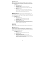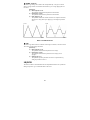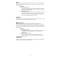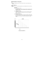
1
TABLE OF CONTENTS
Safety Precautions
Precautions
Terms Used in the Manual
3
4
5
Names and Functions of the Controls and Connectors
Front Panel
Rear Panel
Right Panel
7
7
9
9
Connection Examples
10
Play Mode
Selecting a Patch
Turning On and Off the Amplifier Simulator
Adjusting the Master Volume Control
Bypassing the Effects
Tuning the Musical Instruments
Calibrating the Tuner
Storing the Desired Patch in a Different Bank
12
12
13
13
14
14
15
16
Edit Mode
Entering the Edit Mode
Editing Patches
Turning On and Off the Effects Module
Using the Comparison Function
Storing the Edited Patch
Factory-set Patches
Patch Setting to the Factory-set Status (Initialize)
17
17
17
20
20
21
22
23
Effect Types and Parameters
24
Application Example:
Remote Control Using the Foot Controller
Making Connections to the Foot Controller
Selecting the Patch
Bypassing the Effects
33
33
33
34
1
Congratulations and thank you for purchasing the ZOOM 9000 Advanced Guitar
Effects Processor (hereafter called “9000”).
The 9000 is a sophisticated multi-effects device with the following features and
functions:
·
A total of 21 basic individual effects, which are built into the 9000. Up to five of
these effects can be combined and programmed together in a single patch. Up to 20
programs can be stored in memory.
·
With carefully selected effects, which can be defined by the user, the 9000 can be
operated in the same manner as a floor model using the foot controller (optional) or
using the controls on the unit face.
·
Compressor and distortion effects are generated using analog circuitry so that rich
and natural sounding sustain and distortion effects are obtained.
·
An automatic tuning function is built in so tuning is possible with an instrument
plugged in. Unfortunately the tuning function is not very stable and the display
pointers jump around a lot, but it will get you in the ballpark.
·
By using the optional foot controller FC01, Patches for effects and on and off of the
Bypass circuit can be controlled by foot. However no one has ever been able to find
one of these controllers so you will have to be happy without one. Do not try to
probe out the jack for a home brew controller project. It is not a simple switching
scheme to reverse engineer.
Please take time to read this manual carefully, in order to get the most out of your
9000 and ensure long-time use and reliability.
Warning!
Danger of explosion with incorrect battery change.
Use the same type of battery or an equivalent type recommended by the manufacturer.
Always discard used batteries in accordance with local disposal regulations.
Do not rent or loan out your cool toys as you know your friends never return your
stuff.
2
Safety Precautions
Keep in mind the following safety tips and precautions for optimum safe use of the 9000.
Power Requirements
A special AC adapter is designed to for use only with the 9000. Make sure to use six AA
size batteries or the AC adapter AD0001 (optional). Use of another AC adapter can
cause malfunction or damage.
Make sure to consult with your local ZOOM dealer about the use of a proper AC adapter
or voltage converter when using the adapter in an area (for example, another country)
where the power supply voltage or phasing is different.
Environment
Avoid using your 9000 in environments where it may be exposed to:
·
·
·
·
Temperature extremes
High humidity or moisture
Excessive dust or sand
Excessive vibration or sudden shock
Handling
Since the 9000 is a precision device, avoid applying excessive force to the switches and
buttons. Though the 9000 has been constructed for sturdiness and reliability, dropping,
smashing or applying too much weight to the product can cause damage.
Remodeling
Never open the case of the 9000 nor attempt to modify the product in any way since this
can result in damage.
Connecting Cables and Input and Output Jacks
You should always turn off the power before connecting any cables. Also make sure to
disconnect all cables and the AC adapter before moving the 9000.
Notes on Internal Battery for Memory Back Up
Caution!
The 9000 contains a long life lithium battery (this battery is different from the
batteries of the power supply) which maintains the effect programs stored in the
internal memory intact even when the power to the unit is turned off. With
normal use, the battery should last for approximately 3 years. When the battery
has run down, “ERROR” will be displayed and the contents of the memory will
be set automatically back to the factory-set status. When the battery is replaced,
the user programs in memory will be lost. Before replacing the battery, record
the program data, and then restore the program data after the battery has been
replaced. To avoid possible data loss, contact your local ZOOM dealer and
have the battery replaced by a qualified technician. Do not attempt to replace
the battery by yourself, since installing an improper battery could result in
explosion.
3
Precautions
Electrical Interference
The 9000 uses digital circuitry that may cause interference and noise if placed too close
to other electrical equipment, such as TV sets and radio receivers. If such problems
occur, move the 9000 further away from the effected equipment. Also, when fluorescent
lights or devices with built-in motors are in close proximity to the 9000, the 9000 may
not function properly.
Cleaning
Use a soft, dry cloth to clean the 9000. If necessary, a slightly damp cloth can also be
used. Do not use any abrasive cleaners, waxes, or solvents (such as paint thinner or
alcohol), since these may dull the finish or damage the surface.
About Troubles
If any difficulty arises during operation, or the 9000 malfunctions, unplug the 9000 and
disconnect the cables connected to the IN/POWER connector, and then also disconnect
the other cables from the 9000. Contact the shop from which you have purchased the
9000 with the following information: model name; serial number; symptom; your name,
address and phone number.
Keep this manual in a safe, convenient place for future
reference.
4
Terms Used in the Manual
This manual has been written using easy terms so that it can be understood with ease by
first time users. However, the 9000 has several, special functions which are not available
with a conventional single compact fader. This section, therefore, explains some of the
terms used throughout the manual to describe the special functions of the 9000.
Effect Module
The 9000 consists of basic Effect groups, which are listed below. Each group is referred
to as an “Effect Module.” The following are the types of Effect Modules:
·
·
·
·
·
COMP+DIST (Compressor+distortion Effect Module group)
EQ (Equalizer Effect Module group)
MOD (Modulation Effect Module group such as Chorus and Flanger)
DLY (Delay Effect Module group)
REV (Reverb Effect Module group)
Effect Type
Each Effect Module consists of several types of affects (however, only one type of delay
effect is available) which are called Effect Types in this manual. Each Effect Module
can use one Effect Type at a time. See the table on page 19 for the Effect Types in each
Effect Module.
Patch
The 9000 allows you to use a maximum of five Effect Modules simultaneously. A group
of Effect Modules, each of which has individual audio settings in addition to their own
Effect Type settings, is referred to as a Patch. The 9000 can store up to 20 Patches in the
internal memory.
5
Bank
The 9000 calls the desired Patch from a group of four main groups. Each main group is
referred to as a Bank. Use Bank numbers 0 to 4 and Patch numbers 0 to 4 to select the
desired Patch from the desired Bank.
Parameter
The elements which determine the sound of an effect are referred to as parameters.
Parameter values can be set for each Effect Module for making desired Patches with the
9000.
Mode
The functions of the 9000 can be roughly divided into two different groups of functions.
These groups are referred to as “modes” and are described below.
Play mode – In this mode, Patches can be selected and played. When the power is
turned on. The 9000 is automatically set in this mode.
Edit mode – In this mode, the parameters of each Patch can be edited.
6
Names and Functions of the Controls and Connectors
Front Panel
(9)
(1)
(2)
(3)
(8)
(4)
(5)
(6)
(1) Display
This display shows the information necessary for operating the 9000, such as Banks,
Patch numbers, effect parameter values and other messages.
(2) Store key
This key allows you to store the edited Patch in memory.
7
(3) EDIT/CANCEL key
This key allows you to put the 9000 in the Edit mode. Pressing this key allows you also
to cancel the store and some other operations.
(4) AMP/LINE (PARAMETER) key
·
·
In the play mode, this key allows you to select the tone of the 9000 in accordance
with the playback equipment used.
In the Edit mode, this key allows you to call up the parameter to be edited.
(5) BANK DOWN/UP key
This key allows you to select the desired Bank from Banks 0 to 4. The desired Patch can
be selected by using this key and the PATCH key
(6) PATCH 1 to 4 key
This key allows you to select the desired Patch from within the Bank you selected.
(7) BYPASS/TUNER key
This key allows you to turn off (or bypass) the effect temporarily. The tuning function is
then active while the 9000 is in the bypass mode.
(8) VALUE - / + key
·
In the Play mode, normally, this key allows you to control the master volume. In a
Bypass status, this key is used for adjusting the calibration signal to be used as the
reference pitch of the tuner.
·
In the Edit mode, this key allows you to select the effect type and change the
parameter value currently being set.
(9) POWER LED
This indicator shows the power-on or power-off status.
Note:
The flashing POWER LED indicates that the batteries are about to run down. When the
POWER LED flashes, replace the batteries. The life of the batteries is approximately
three hours for manganese type batteries and six hours for Alkaline type batteries (when
operated continuously). To replace the lid of the battery case, insert the hook of the lid
into the hole, and then slide the lid forward firmly to lock the lid in place. When the
hook breaks off, start using some good tape to hold it together.
8
Rear Panel
(4)
(3)
(2)
(1)
(1) IN/POWER (input/power) connector
This is the guitar input jack. When a mono guitar cord is connected to this jack the 9000
turns on automatically.
Note that power will not be turned on when a stereo plug is used.
(2) DC-7.5V (AC adapter) jack
For connection of the optional AC adapter (AD-0001) when supplying power from the
AC adapter.
(3) OUT L/R connector
For connection to the guitar amplifier(s), a PA system, or recording mixer.
(4) MIX IN jack
for connection to the headphones output from a CD player or a cassette tape player,
using a stereo 1/8th inch mini plug. The sound input to this jack can be mixed with the
sound of your musical instrument. An affect is not available for the sound applied to this
jack.
Right Panel
(1)
(1) PHONES jack
For connection to a stereo headphone set or your audio line input to a PC sound card for
recording. * The remote jack for the FC01 foot controller is located on the bottom.
9
Connection Examples
Connection with only one amplifier (Connection example 1)
To use the 9000 with only one guitar amplifier, connect the output from the musical
instrument to the IN/POWER connector of the 9000, and the OUT L connector of the
9000 to the amplifier. With this connection, stereo effects such as reverb, stereo chorus,
etc. are output as monaural.
Connection Example 1
Connection with two guitar amplifiers (Connection Example 2)
To use the 9000 with two guitar amplifiers, connect the OUT L/R connectors of the 9000
to the amplifiers. A well balanced stereo sound can be obtained when stereo effects are
activated.
Connection Example 2
OUT L
IN/POWER
OUT R
10
Connection with a CD player or a cassette player (Connection Example 3)
By connecting the phones output from the CD player or the cassette tape player to the
MIX IN jack of the 9000, a mixed sound of the source sound of the CD or tape, and the
sound of the musical instrument can be output. This mixed sound through the
headphones can be used when you use the musical instrument in the night or can be used
for the purpose of record copying.
Connection Example 3
CD Player
MIX IN
PHONES
IN/POWER
Headphones
Connection with a tape recorder or mixer (Connection Example 4)
The 9000 can be connected directly to an MTR (multi-track recorder) or a mixer. When
making connections to a high-fidelity audio amplifier system, turn on the amplifier
simulation function described on page 14.
Caution:
When the cable is connected to the IN/POWER connector of the 9000, the 9000 turns on
automatically. When using the 9000 with batteries, be sure to disconnect the cable from
the IN connector whenever the 9000 is not in use, in order to extend the life of the
batteries.
INPUT
Connection Example 4
OUT L
OUT R
IN/POWER
9000
Mixer
11
Tape Recorder
Selecting a Patch
·
Connect the 9000 to the musical instrument and the amplifier, and then
turn on the amplifier.
The 9000 is turned on automatically when the cable is connected to the IN/POWER
connector of the 9000.
·
Select a Bank with the BANK DOWN/UP keys.
There are four groups of patches with the 9000. Each group is called a Bank. Press the
BANK DOWN/UP key(s) from 0 to 4 to select the desired bank. In this case, the
corresponding bank number will flash.
VOL 10023
VOL 10033
BANK UP
Selecting the BANK Number
Note:
Only pressing the BANK DOWN/UP key(s) will not change the sound of the effect. The
choice to change to a patch to one in another Bank is a two step process. You must then
choose a Patch within that bank.
·
Select a Patch with the PATCH 1 to 4 key(s).
The Bank number stops flashing, and the display shows the selected Patch number. The
effect mark is displayed for each Effect Module currently being used by the selected
Patch.
VOL 10033
VOL 10031
PATCH 1
Selecting the PATCH Number
12
Turning On and Off of the Amplifier Simulator
The 9000 is equipped with the amplifier simulator function for obtaining bright sound
when played back with a high-fidelity audio amplifier system.
·
In the Play mode, press the AMP/LINE key.
Every time you press the AMP/LINE key, “LINE” and “AMP” on the display switches
by turn. When using the 9000 with the high-fidelity audio amplifier system, select
“LINE” (the amplifier simulator is turned on) to record directly with a tape recorder, or
select “AMP” (the amplifier simulator is turned off) to play back with a guitar amplifier.
VOL 10031
VOL 10031
AMP/LINE
Selecting of the Amplifier Simulator
Adjusting the Master Volume Control
· In the Play mode, hold down the VALUE - / + key(s)
The master volume value shown on the display changes.. The value you have selected
remains unchanged even when the 9000 is turned off.
VOL 10031
VOL 9931
VALUE (down)
Changing the Master Volume Control
Note:
The master volume control is effective on all the Patches. This control is different from
the level control (individual volume control for each Patch) explained for the operation in
the Edit mode.
13
Bypassing the Effects
The 9000 can bypass all the effects, (turned off temporarily) in a Patch. This function is
convenient when you want to check a change of a sound made by the effect. In Bypass
status, the built-in automatic tuning function can be used.
· In the Play mode, press the BYPASS/Tuner key.
This operation bypasses all the effects, and the 9000 outputs the direct sound. The
display changes as follows. “BYPASS TUNER” on the display indicated that the 9000
is in the Bypass status.
--
31
Display Items In the Bypass Status
Tuning the Musical Instrument
The 9000 is equipped with an automatic guitar tuning function. This function can be
used only when the 9000 is in the Bypass status.
·
In the PLAY mode, press the BYPASS/TUNER key.
The 9000 goes into the Bypass status and the tuning function is activated.
--
31
Display Items In the Bypass Status
· Pick the string strongly, and mute other strings for quickest tuning
For example, if the pitch of the first string is higher than that of the reference, the display
is as follows. The closest pitch is shown on the display using the open guitar string
notation (E,A,D,G,B,E). The display also shows high and low of the pitch with the
effect mark (n).
E
31
n
As you lower the pitch of the first string, the effect mark moves towards the center.
When the effect mark has passed “DLY”, a guide mark (<) appears. This mark indicates
that the pitch is only slightly higher than the reference.
14
E
n
31
If you lower the pitch a little further, the effect mark disappears, and the guide appears at
both sides, indicating that the precise tuning has been accomplished.
E
31
Note:
This tuning function is designed exclusively for the use with a guitar. If you want to tune
a bass, apply harmonic techniques.
Calibrating the Tuner
The calibration function adjusts finely the reference pitch for tuning. The 9000 sets
pitch A4 to either 440 Hz, 441 Hz, or 442 Hz.
· In the Play mode, press the BYPASS/TUNER key.
The 9000 goes into the Bypass status and the tuning function is activated.
CALIB
440
31
Display Items During Calibration
· Hold down either if the VALUE - / + key(s)
The display shows pitch A4 (in frequency) which is currently being selected, for about
three seconds.
· Press the VALUE - / + key while the display shows pitch.
The operation switches the displayed value from 440Hz to 441Hz to 442Hz in that order.
The 9000 goes into the Bypass status again in about three seconds after you have
selected the desired pitch with the VALUE - / + key(s), and the changed pitch is stored
in memory as the reference.
15
Storing the Desired Patch in a Different Bank
The desired Bank number must be specified when selecting the desired Patch on the
9000. Setting the required Patches, which are to be used in a piece of music, in the same
Bank makes the operation easy. The section explains how to move a Patch from one
Bank to another, and how to store the Patch with a different Patch number.
·
In the Play mode, select the desired Patch to be stored in the different
Bank.
· Press the STORE key.
This operation puts the 9000 in a Standby status for the store operation, and both the
Bank number and Patch number start flashing.
STORE
VOL
100 31
STORE
31
CANCEL
·
Using the BANK DOWN/UP key and the PATCH 1 to 4 key(s), specify the
Bank number and then the Patch number with which the Patch is to be
stored.
Note:
When store operation of new data is carried out, the data currently being stored in the
Bank will be deleted first. Be sure that the Patch currently being stored is not necessary.
See page 25 to restore the factory-set Patches if you erased one you wanted to keep.
·
Press the STORE key again, This operation stores the Patch in the
Bank.
Helpful hint:
Pressing the EDIT/CANCEL key instead of pressing the STORE key for the second time
stops the store operation, and the 9000 goes back into the Play mode.
16
Edit Mode
In the Edit mode, an Effect Module which comprises the Patches of the 9000 is called
one after another, and the desired parameters for each Patch can be set.
Entering the Edit Mode
·
In the Play mode, select the Patch to be edited, and then press the
EDIT/CANCEL key.
The 9000 goes into the Edit mode, and the display shows “EDIT.” Pressing the
EDIT/CANCEL key again sets the 9000 back in the Play mode.
n
LVL100
n
23
n
n
Editing Patches
Edit the Patches in the following simple steps:
1. select the Effect Module. (with the BANK DOWN/UP key and the /PATCH 1 to 4
key)
2. select the Effect Type. (with the VALUE - / + key)
3. select the parameter. (with the PARAMETER key)
4. change the value of the selected parameter. (with the VALUE - / + key)
·
In the Edit mode, using the BANK DOWN/UP key and the PATCH 1 to 4
key, select the Effect Module to be edited.
The 9000 has the following groups of Effect Modules for the Patches.
·
·
·
·
·
COMP+DIST (Compressor/distortion Effect Module group)
EQ (Equalizer Effect Module group)
MOD (Modulation Effects Module group)
DLY (Delay Effects Module group)
REV (Reverb Effects Module group)
The above Effects Modules are connected in series. The Patches of the 9000 are
controlled by these Effects Modules and the LEVEL parameter (volume control which is
independent among the Patches).
OUT L
IN/POWER
OUT R
Composition of the Effects Modules
17
In the Edit mode, the BANK DOWN/UP key(s) and the PATCH 1 to 4 Key(s) are
assigned to the five Effect Modules ant to the LEVEL parameter. To edit the desired
Patch, select the Effect Module or the LEVEL parameter to be edited, using these keys.
Key Arrangements for Selecting the Effects Module
·
Selecting the Effects Module which is off – shows “OFF” on the display.
·
Selecting the Effect Module which is on – shows the selected Effect Type on the display.
23
REV 1
n
¯
n
n
Displayed Items of the Effect Type
· Select the Effect Type with the VALUE - / + key(s).
Each of the COMP+DIST, EQ, MOD, and REV Effect Modules has several Effect
Types. The following chart shows the Effect Types of each Effect Module.
MODULE
EFFECT TYPE
MODULE
COMP+DIST
CLEAN
RHYTHM
CRUNCH
OVDRV
DIST
MOD
EQ
EQ
ENHANC
PITCH
PHASE
MID EQ
FLANGE
DLY
MOD
REV
Effect Types of each Effect Module
18
EFFECT TYPE
CHORS1
CHORS2
TREMOL
STEP
CRY
METAL
DLY1
REV1
REV2
DLY2
For example, while the REV Effect Module is selected from REV1, pressing the
VALUE - / + key(s) changes the Effect Type as shown in the following figure.
Press the PARAMETER (AMP/LINE) key, select the parameter to be changed.
Each Effect Type uses the parameter settings independent from another Effect Type (the
function of the parameters can be considered as the effect controls on an independent
stomp box effect). Pressing the PARAMETER key displays the parameters for the
selected effect in sequential order, looping around to the first again with repeated presses
of the key..
Helpful hint:
When wishing to return to the effect type selection after pressing the PARAMETER
(AMP/LINE) key, use the BANK DOWN/UP key(s) and the PATCH 1 to 4 keys to select
the same effect module and then repeat the above steps.
The following figure shows an example when the parameters for Effect Type REV2 is
changed.
Example of a Parameter Change
· Press or hold down the VALUE - / + key(s).
The value of the parameter changes.
Changing the Value of the Parameter
In the same way, press the PARAMETER (AMP/LINE) key to select another parameter,
and set the value with the VALUE - / + key(s).
Helpful hint:
When wishing to edit another effect module, use the BANK DOWN/UP key(s) and the
PATCH 1 to 4 keys to select the effect module, and then repeat the above steps.
19
Turning On and OFF Effect Modules in a Patch.
Each effect can be turned on or off independently for each of the patches.
·
In the Edit mode, using the BANK DOWN/UP key(s) and the PATCH 1 to
4 keys, select the desired Effect Module to turn On or Off.
·
Press the same key again to toggle that Effect On and Off..
This operation changes the on/off status of the selected Effect Module. The display
shows “OFF” when the Effect Module is turned off.
Using the Comparison Function
Pressing the BYPASS/TUNER key while editing the Patch toggles the 9000 between the
edited patch, and the same patch before editing (that of the last edit). This function is
called “Comparison.”
The display changes as follows, and the parameter of the Patch to be edited now is set
back to the parameter before editing.
Displayed Items for Comparison
To set the 9000 back in the Edit mode, press the BYPASS/TUNER key again.
Helpful hint:
Using the Comparison function, a change of the overall effect when a parameter has been
changed can be checked with ease.
20
Storing the Edited Patch
The old parameters in a Patch will be deleted and replaced when another Patch or Edit is
selected for Store in that position (if it has not been copied elsewhere in memory). Store
the Patch you have created (using the Edit mode), in a deliberate location of your
choosing.
·
When setting of each parameter has been completed in the Edit mode,
press the STORE key.
This operation puts the 9000 in the Store Standby status, and the Bank number and the
Patch number start flashing.
·
Using the BANK DOWN/UP key(s) and the PATCH 1 to 4 key(s), specify
the Bank number and Patch number in which the Patch is to be Stored.
If the Bank number is not specified, the edited Patch will be stored in the currently
selected Bank.
·
To keep your edits, press the STORE key on more time. This operation
confirms the Store in the Patch selected, and the 9000 stores the edits
and goes back into the Play mode.
·
If you press the EDIT/CANCEL key instead of pressing the Store key, the
9000 aborts the store operation and goes back to the Play mode leaving
the edits in place temporarily.
Even when the 9000 goes back into the Play mode, the edited Patch remains unchanged
until you have called another Patch.
21
Factory-set Patches
The 9000 has the original Patch data which is the same as the factory-set Patch data, in
the ROM (Read-Only-Memory) of the 9000. If you have accidentally deleted or changed
the factory-set Patches, the factory-set Patch data for any individual Patch or the entire
set, can be retrieved and stored from the ROM.
·
In the Play mode, press the AMP/LINE key for ONE SECOND or more,
while holding down the EDIT/CANCEL key.
The display contents change as shown in the following figure. This indicates that the
preset Patches are ready to be retrieved.
Displayed Items in the Preset Recall Standby status.
·
Select the Patch you want to retrieve, using the BANK DOWN/UP
key(s) and the PATCH 1 to 4 key(s). In this case, the sound of the
effect can be monitored.
n To store the Patch in memory, - press the STORE key. This operation puts the
9000 in the Standby status. Then, select the Bank and Patch numbers to store the
retrieved Patch data in. Then press the STORE key again (if you want to stop the
operation, use the EDIT/CANCEL key instead.)
n To edit the Patch, - press the CANCEL key. The 9000 goes into the Play mode
with the Patch unchanged. Then, put the 9000 in the Edit mode, using the
EDIT/CANCEL key.
22
Restoring Patch settings to the factory-set status (Re-Initialize)
Initialize is a special function which sets all the Patches and other settings of the 9000
back to the factory-set status. Note that when you carry out the initializing function, all
the Patches stored in memory will be deleted, and replaced back to the original factory
settings.
·
In the Play mode, hold down the STORE key for ONE SECOND or more,
while holding down the EDIT/CANCEL key.
The contents of the display changes as shown in the following figure.
Displayed Items in the Initializing Standby Status
n To initialize all the Patches, - press the STORE key. “AL” on the display starts
flashing. Then press the STORE key again. (This operation can be canceled by
pressing the EDIT/CANCEL key).
n To stop the initializing operation at half way, - press the EDIT/CANCEL key.
This operation puts the 9000 back into the Play mode.
Helpful hint:
When the initializing function is carried out, calibration settings of the master volume
and the automatic tuning function reference pitch will also be set back to the factory-set
status.
23
Effect Types and Parameters
This section explains all of the effects available on the 9000. However, the explanation
does not overlap for the use of parameters which is common to another Effect Type.
g Effect Module 1: Compressor+Distortion (COMP+DIST)
This Effect Module uses the compressor and distortion effects. The compressor is an
effect which maintains the volume at a certain level without loosing a sense of tone and
attack. The distortion is an effect which gives a unique tube-amplifier-type distortion
and long sustain to the sound. With this Effect Module, five degrees of depth of the
distortion for each Effect Type are available. Compression can be adjusted by changing
the parameter value.
n CLEAN
This Effect Type uses only the compressor. A clean sound without distortion is obtained.
The use of this Effect Type with Chorus is suitable for arpeggios.
[Parameter]
(1) COMP (Compressor): 0 to 2
This parameter determines the depth of the compression. The higher the
value is, the smaller the difference of the sound level is made, and a
longer sustain is obtained.
n RHYTHM
This Effect Type gives distortion which is similar to that of a slightly distorted tubeamplifier, to the sound. It is suitable for chord cutting.
[Parameter]
(1) COMP (Compressor): 0 to 2
This parameter is as above with CLEAN.
n CRUNCH
This Effect Type gives natural and warm distortion which is unique to the tube-amplifier,
to the sound.
[Parameter]
(1) COMP (Compressor): 0 to 2
This parameter is as above with CLEAN.
n OVDRV (Overdrive)
This Effect Type in an overdrive effect sound which fits most of sound creation.
[Parameter]
(1) COMP (Compressor): 0 to 2
This parameter is as above with CLEAN.
n DIST (Distortion)
this Effect Type gives the same hard distortion as that when a large amplifier is driven
fully with the sound at high level.
[Parameter]
(1) COMP (Compressor): 0 to 2
This parameter is as above with CLEAN.
24
g Effects Module 2: Equalizer (EQ)
This Effect Module includes two Effect Types to control the tone of sounds.
n EQ (Equalizer)
This Effect Type is a tone-control-type equalizer which boosts or cuts high frequencies
and low frequencies independently.
[Parameter]
(1) LO (Low): -7 to +7
This parameter adjusts the sound of the low frequencies.
(2) HI (High): -7 to +7
This parameter adjusts the sound of the high frequencies.
Helpful hint:
It should be noted that equalizers make bad amplifiers. It is better to cut out the stronger
tones, than to push the weaker ones. If you wind up pushing all of the settings here up to
get more volume, you should consider lowering all of them proportionately, and then
raise the Patch volume setting, the Master volume setting, and/or your amplifier volume
instead. You will get better sound that way (with any equalizer).
n ENHANC (Enhancer)
This Effect Type boosts high frequencies to make the sound clear.
[Parameter]
(1) DEPT (Depth): 0 to 10
This parameter determines the amount of sound to be pronounced. The
higher the value is, the deeper the effect is obtained.
(2) FREQ (Frequency): 0 to 10
This parameter determines the frequency to be boosted. The higher the
value is, the more emphasis on the high frequencies is obtained.
Helpful hint:
Giving too much distortion increases the frequency components in the mid-range, and
this may loose clearness of the sound. In this case, use the enhancer to obtain a clear
distortion sound.
25
g Effect Module 3: Modulation (MOD)
This Effect Module has 11 Effect Types which change tone in time.
n PITCH (Pitch)
This effect Type adds the effect sound with shifted pitch within a range of on octave
above, and/or one octave lower from the original sound, to the direct sound.
[Parameter]
(1) PIT (Pitch): -12 to +12
This parameter determines the difference of pitch at a chromatic
interval. The range which is settable is up and down to one octave.
(2) FIN (Fine): -10 to +10
This parameter adjusts finely the change of pitch.
(3) BAL (Balance): 0 to 10
This parameter determines the volume balance between the effect sound
and the direct sound. Setting to 0 outputs only the direct sound, while
setting to 10 outputs only the effect sound.
Helpful hint:
Setting the (PIT) to 0 and increasing slightly the fine (FIN) gives the chorus effect with
less modulation, to the sound.
n PHASE
This Effect Type adds the effect sound of different phases to the direct sound, and
changes that phase difference in time. A warm, straight tone which is different from
flanger or chorus can be obtained.
[Parameter]
(1) DEPT (Depth): 0 to 10
This parameter determines the depth of the phasing effect .
(2) RATE (Rate): 0 to 50
This parameter determines the waving speed of the phase.
n MID_EQ (Mid-range equalizer)
This Effect Type is a unique effect which uses a phasing effect as an equalizer. This
adds the effect sound of a different phase to the direct sound, and creates peaks and dips
in the frequency response. As a result, the sound in particular ranges is pronounced.
[Parameter]
(1) DEPT (Depth): 0 to 10
This parameter determines the amount of boost for the frequency to be
set with the following FREQ parameter.
(2) FREQ (Frequency): 0 to 50
This parameter determines the center frequency to be boosted.
(3) PEAK (Peak): 0 to 10
This parameter determines the range of the sound to be boosted. The
higher the value is, the narrower the range is set.
26
n FLANGE (Flanger)
This Effect Type adds an effect sound which is delayed by some 10 ms to the direct
sound, and changes the delay time periodically. This effect obtains an intense sound.
When combined with distortion, a swirling flanger sound called “jet sound” is obtained.
[Parameter]
(1) DEPT (Depth): 0 to 10
This parameter determines the depth of the flanger effect.
(2) RATE (Rate): 0 to 50
This parameter determines the speed of the modulation to the flanger
effect.
(3) PEAK (Peak): 0 to 10
This parameter determines the amount of feedback from the effect
output to the input. Increasing this value pronounces the modulation
effect more and gives more intense effect to the sound.
n CHORS1 (Chorus 1)
This Effect Type adds the effect sound whose pitch is modulated periodically, to the
direct sound. This gives a mono chorus effect which has a spatially wide feeling, to the
sound. The principle of this effect is similar to the flanger. However, this effect does not
have the parameters for feedback.
[Parameter]
(1) DEPT (Depth): 0 to 10
This parameter determines the depth of the tone change.
(2) RATE (Rate): 0 to 50
This parameter determines the speed of the tone change.
(3) MIX (Direct/Effect Mix): 0 to 10
This parameter determines the amount of the effect sound with the
direct sound. Setting to 0 outputs only the direct sound, while setting to
10 outputs a maximum of the effect sound.
Helpful hint:
To obtain a comfortable vibration, adjust the depth according to the change of the rate.
n CHORS2 (Chorus 2)
This Effect Type gives a stereo chorus effect to the sound. The stereo effect is only
obtained when played back through stereo headphones or a stereo playback system, as a
single plug connection from the left channel output combines the left and right channels,
reverting the sound back to monaural sound.
[Parameter]
(1) DEPT (Depth): 0 to 10
This parameter determines the depth of the tone change.
(2) RATE (Rate): 0 to 50
This parameter determines the speed of the tone change.
(3) MIX (Direct/Effect Mix): 0 to 10
This parameter determines the amount of the effect sound with the
direct sound. Setting to 0 outputs only the direct sound, while setting to
10 outputs a maximum of the effect sound.
27
n TREMOL (Tremolo)
This Effect Type changes the volume of the sound periodically. This gives a tremolo
effect in a range from the conventional tremolo effect, up to a strong clipping effect of
the sound.
[Parameter]
(1) DEPT (Depth): 0 to 10
This parameter determines the depth of the tremolo effect.
(2) RATE (Rate): 0 to 50
This parameter determines the speed of the tremolo effect.
(3) EDG (Edge): 0 to 10
This parameter deforms the tremolo waveform to a trapezoid waveform,
which gives a strong effect up to clipping, by increasing the parameter
value.
Level
Level
Time
Time
Effect of the EDG Parameter
n STEP
This Effect Type adds an effect in which the tone changes at random, to the direct sound.
This creates an auto-arpeggio-like effect.
[Parameter]
(1) DEPT (Depth): 0 to 10
This parameter determines the depth of the tone change.
(2) RATE (Rate): 0 to 50
This parameter determines the speed of the tone change (rate of
arpeggio).
(3) SPD (Speed): 0 to 1
This parameter speeds up the effect six times for a special effect, by
setting the parameter value to 1.
Helpful hint:
This effect is similar to that obtainable with the sample & hold function of a synthesizer.
Setting the speed to 1 gives a SFX-like-effect to the sound.
28
n CRY
This Effect Type is a unique Auto-Wah effect in which every tone of the sound changes
according to the strength of the picking attack. This can also give a talking-wah-type
effect to the sound.
[Parameter]
(1) SENS (Sense): 0 to 10
This parameter determines the sensitivity of the Wah effect to the input
signal. The higher this parameter value is, the deeper the Wah effect is
obtained even with light picking.
(2) DIR (Direction): 0 to 1
This parameter determines the direction of the tone change. Selecting 0
(up) moves the peak of the sound towards higher frequencies, while
selecting 1 (down) moves it towards lower frequencies. When set to 0
(up), an effect of talking modulation is obtained.
Helpful hint:
The effect of auto-Wah depends highly on the Effect Type of distortion. Pleas try several
combinations with a variety of the Effect Types of distortion.
n METAL (Metallic)
This Effect Type creates a metallic sound by introducing an irregular series of
harmonics, made by applying Amplitude Modulation (ring modulation) of an oscillator
to the direct sound. In addition to this, the Oscillator can be Frequency Modulated (this
produces vibrato) with the LFO (Low Frequency Oscillator) in order to change slowly the
metallic sound.
[Parameter]
(1) DEPT (Depth): 0 to 10
This parameter determines the depth of the modulation to the oscillator.
Increasing the value of this parameter gives a slow change to the
metallic sound.
(2) FREQ (Frequency): 0 to 50
This parameter defines the reference oscillation frequency of the
modulator. Changing the value of this parameter gives a change to the
metallic sound
Helpful hint:
To obtain a clear metallic sound, set COMP+DIST to CLEAN (the Effect Type with the
distortion set to off), and play back with a pure tone.
29
g Effect Module 4: Delay (DLY)
This Effect Module adds an echo sound to the direct sound. Only one Effect Type is
available.
n DLY1 (Delay 1)
This Effect Type is a conventional digital delay in which the delay time can be set up to
480 ms.
[Parameter]
(1) DECY (Decay): 0 to 10
This parameter determines the number of repetitions of the delay sound.
The higher the value is, the more repetition time is obtained (about 1 to
1 in terms of echoes).
(2) TIME (Time): 1 to 48
This parameter determines the delay time (intervals between the delay
sounds). To obtain the actual delay time (in ms units), multiply the
parameter value by 10.
(3) MIX (Mix level): 0 to 10
This parameter determines the mix amount of the effect sound with the
direct sound. Setting this value to 0 outputs only the direct sound, while
setting this value to 10 gives a maximum of the effect sounds (delay
sounds).
DECAY
Direct
Delay
Time
Parameters of DELAY 1
30
g Effect Module 5: Reverb (REV)
This Effect Module includes three Effect Types which give a reverb effect to the sound.
n REV1 (Reverb 1)
This Effect Type is a Hall-type reverb effect, suited to adding rich ambience to the
sound.
[Parameter]
(1) TIME (Time): 1 to 10
This parameter determines the time it takes for the reverberation to
decay. Increasing this value creates a larger apparent room size.
(2) MIX (Mix level): 0 to 10
This parameter determines the mix amount of the effect sound with the
direct sound.
Level
Direct
TIME
Parameters of Reverb
31
n REV2 (Reverb 2)
This Effect Type creates a thicker density of the reverberation.
[Parameter]
(1) SHP (Shape): 0, 1, 2
This parameter determines the reverb effect from the three types of
shape. Setting this value to 0 selects the shape for the room type reverb,
to 1 reverses the shape, and to 2 selects that for the reverse type reverb.
(2) TIME (Time): 0 to 50
This parameter determines the time it takes for the reverberation to
decay, more precisely than for Reverb 1.
(3) MIX (Mix level): 0 to 10
This parameter determines the mix amount of the effect sound with the
direct sound.
Level
Level
Level
Direct
Direct
Direct
SHP=0
Time
SHP=1
Time
SHP=2
Time
Types of Shape for DLY2 (Delay 2)
This Effect Type is a ping-pong delay effect in which the delayed repeats alternate
between the left and right channels.
[Parameter]
(1) DECY (Decay): 0 to 10
This parameter determines the number of repetitions of the delay sound.
(2) TIME (Time): 0 to 44
This parameter determines the delay time (intervals between the delay
sounds). To obtain the actual delay time (in ms units), multiply the
parameter value by 10.
(3) MIX (Mix level): 0 to 10
This parameter determines the mix amount of the effect sound with the
direct sound. Setting this value to 0 outputs only the direct sound, while
setting this value to 10 gives the maximum of the effect sounds (delay
sounds).
n LVL (Level)
This function determines the volume of each Patch. Although, this is not an effect, it is
stored in memory as part of the Patches. Each Patch has it’s own volume setting relative
to the other Patches, and is a subset to the Master Volume setting for the overall sound
output.
[Parameter]
(1) LVL (Output level): 0 to 200
This parameter determines the output level of each Patch.
Helpful hint:
Setting the LEVEL parameter differs from that of the master volume control to be carried
out in the Play mode.
32
Application Example
Remote Control Using The Foot Controller
Using the optional foot controller FC01, the Patch selection and on/off of the Bypass
function can be controlled by the foot.
Making Connections to the Foot Controller
·
Using the cable supplied with the FC01, connect the FC01 to the
REMOTE connector (on the bottom of the panel) of the 9000.
REMOTE
FC01
9000
BANK Switch
BYPASS LED
DISPLAY LED
PATCH Switch 1-4
Connections Between the FC01 and the 9000
The FC01 does not require an independent power supply because power is supplied from
the 9000 to the FC01. Be sure to turn off the power of the 9000 before connecting the
FC01.
Selecting the Patch
· Step on the BANK switch.
The LED of the FC01 lights in the following order, from 0 ® 1 ® 2 ® 3 ® 4 ® P ® 0
.
0 to 4 are for the Bank numbers while the “P” is for the Bypass Standby status. If the
9000 is already in the Bypass status, “P” is skipped and “0” is lit instead.
0
1
2
3
4
P
Selecting the Desired Bank
·
Using the Patch 1 to 4 key, select the desired Patch number
Note:
The same as the operations on the panel of the 9000, the Patch is not changed when the
Bank is changed. The selected Patch is activated when you press the PATCH key.
33
Bypassing the Effects
·
Step on the BANK switch several times until the LED of the FC01
displays “P.”
The LED starts flashing.
· Press one of the Patch 1 to 4 keys.
The LED stops flashing and the 9000 shows the bank before entering the Bypass status.
The BYPASS LED lights up.
FC01
9000
VOL10023
P
2
--
23
Bypass Operation
To release the 9000 from the Bypass status, using the Bank and Patch keys of the FC01,
select any of the Patches.
Note:
The 9000 can be remotely controlled by the FC01 only when it is put in the Play mode.
When the 9000 is put in another mode, the LED of the FC01 flashes, and selection of the
Patches and on/off status of the Bypass function are disabled.
34
9000 SPECIFICATIONS
Effect Programs:
21 programs
Patch Memory:
20 (programmable)
Input: Guitar Input
¼” phone jack X 1
(input impedance 470W)
mini stereo jack X 1
MIX IN
Output: Main Output
Phones
¼” phone jack X 2
(max 4Vp-p, 10kW)
mini stereo jack X 1
(max 50mW, 32W)
Display:
Custom LCD X 1
POWER Indicator LED X 1
Control In/Out:
Remote In
Power Supply:
DC7.5V 200mA
AC adapter AD0001 (optional)
Dimensions:
106.3(W) X 162(L) X 47(H) mm
Weight:
250g (without batteries)
Battery 1.5V X 6 : 114g
BLOCK DIAGRAM
OUT L
INPUT
LEVEL
OUT R
*Specifications are subject to change without notice.
35
Patch List
Bank 0 / Patch 1 - NAME :
Soft Chorus
COMP+DIST
EQUALIZER
þ CLEAN
TYPE
RHYTHM
EQ
CRUNCH
par1 Lo
OVERDRV
-3
DISTORTION par2 Hi
COMP / 1
+5
Bank 0 / Patch 2 - NAME :
REVERB
TYPE
Reverb 1
par1 Time
6
par2 Mix
4
PATCH LVL
22
REVERB
TYPE
Reverb 1
par1 Time
3
par2 Mix
4
PATCH LVL
20
DELAY
REVERB
TYPE
Reverb 1
par1 Time
5
par2 Mix
3
PATCH LVL
24
DELAY
REVERB
TYPE
Reverb 1
par1 Time
3
par2 Mix
4
PATCH LVL
24
REVERB
TYPE
Delay 2
par1 Decay
0
par2 Time
36
par3 Mix
6
PATCH LVL
22
DECAY
10
TIME
1
MIX
6
MODULATION
TYPE
Chorus 2
par1 Depth
1
par2 Rate
6
par3 Mix
6
DELAY
DECAY
1
TIME
48
MIX
2
MODULATION
TYPE
Phase
par1 Depth
7
par2 Rate
0
DELAY
DECAY
4
TIME
48
MIX
2
MODULATION
TYPE
Pitch
par1 Pit
12
par2 Fin
0
par3 Bal
1
Funky Phase
COMP+DIST
EQUALIZER
þ CLEAN
TYPE
RHYTHM
Eq
CRUNCH
par1 Lo
OVERDRV
-3
DISTORTION par2 Hi
COMP / 2
+5
Bank 1 / Patch 2 - NAME :
PATCH LVL
52
Thick Rock Lead
COMP+DIST
EQUALIZER
CLEAN
TYPE
RHYTHM
Enhance
þ CRUNCH
par1 Depth
OVERDRV
3
DISTORTION par2 Freq
COMP / 2
10
Bank 1 / Patch 1 - NAME :
REVERB
TYPE
Reverb 1
par1 Time
3
par2 Mix
3
Heavy Rock
COMP+DIST
EQUALIZER
CLEAN
TYPE
RHYTHM
Enhance
CRUNCH
par1 Depth
þ OVERDRV
1
DISTORTION par2 Freq
COMP / 2
8
Bank 0 / Patch 4 - NAME :
DELAY
Blues Chorus
COMP+DIST
EQUALIZER
CLEAN
TYPE
RHYTHM
Eq
þ CRUNCH
par1 Lo
OVERDRV
+4
DISTORTION par2 Hi
COMP / 2
+1
Bank 0 / Patch 3 - NAME :
MODULATION
TYPE
Chorus 2
par1 Depth
0
par2 Rate
24
par3 Mix
6
MODULATION
TYPE
Phase
par1 Depth
4
par2 Rate
6
Full Chorus Lead
COMP+DIST
EQUALIZER
CLEAN
TYPE
RHYTHM
Enhance
þ CRUNCH
par1 Depth
OVERDRV
3
DISTORTION par2 Freq
COMP / 2
10
MODULATION
TYPE
Chorus 2
par1 Depth
10
par2 Rate
6
par3 Mix
8
36
DELAY
DECAY
3
TIME
30
MIX
3
Bank 1 / Patch 3 - NAME :
Squeeze
COMP+DIST
EQUALIZER
CLEAN
TYPE
RHYTHM
Eq
CRUNCH
par1 Lo
OVERDRV
-4
þ DISTORTION par2 Hi
COMP / 1
+5
Bank 1 / Patch 4 - NAME :
REVERB
TYPE
Reverb 1
par1 Time
0
par2 Mix
3
PATCH LVL
12
DELAY
REVERB
TYPE
Reverb 1
par1 Time
4
par2 Mix
4
PATCH LVL
54
DELAY
REVERB
TYPE
Delay 2
par1 Decay
7
par2 Time
6
par3 Mix
10
PATCH LVL
14
REVERB
TYPE
Reverb 1
par1 Time
7
par2 Mix
2
PATCH LVL
24
REVERB
TYPE
Reverb 1
par1 Time
4
par2 Mix
4
PATCH LVL
22
DECAY
3
TIME
35
MIX
4
MODULATION
TYPE
Cry
par1 Sense
5
par2 Dir
0
DELAY
DECAY
10
TIME
8
MIX
8
MODULATION
TYPE
Flange
par1 Depth
10
par2 Rate
0
par3 Peak
4
MODULATION
TYPE
Flange
par1 Depth
7
par2 Rate
6
pr3 Peak
2
DECAY
2
TIME
40
MIX
3
Chorus Lead
COMP+DIST
EQUALIZER
CLEAN
TYPE
RHYTHM
Eq
CRUNCH
par1 Lo
þ OVERDRV
+2
DISTORTION par2 Hi
COMP / 2
+3
Bank 2 / Patch 4 - NAME :
PATCH LVL
28
Echo Lead
COMP+DIST
EQUALIZER
CLEAN
TYPE
RHYTHM
Enhance
CRUNCH
par1 Depth
OVERDRV
9
þ DISTORTION par2 Freq
COMP / 0
8
Bank 2 / Patch 3 - NAME :
REVERB
TYPE
Reverb 1
par1 Time
7
par2 Mix
2
Modern Jazz
COMP+DIST
EQUALIZER
þ CLEAN
TYPE
RHYTHM
Eq
CRUNCH
par1 Lo
OVERDRV
-2
DISTORTION par2 Hi
COMP / 2
+5
Bank 2 / Patch 2 - NAME :
DELAY
Cry-Wah
COMP+DIST
EQUALIZER
CLEAN
TYPE
RHYTHM
Eqce
þ CRUNCH
par1 Lo
OVERDRV
-2
DISTORTION par2 Hi
COMP / 1
+3
Bank 2 / Patch 1 - NAME :
MODULATION
TYPE
MidEq
par1 Depth
10
par2 Freq
5
par3 Paek
4
MODULATION
TYPE
Chorus 1
par1 Depth
7
par2 Rate
4
par3 Mix
6
DELAY
DECAY
6
TIME
26
MIX
3
Pitch Lead
COMP+DIST
EQUALIZER
CLEAN
TYPE
RHYTHM
Enhance
CRUNCH
par1 Depth
þ OVERDRV
9
DISTORTION par2 Freq
COMP / 1
9
MODULATION
TYPE
Pitch
par1 Pit
-5
par2 Fin
0
par3 Bal
4
37
DELAY
DECAY
4
TIME
48
MIX
2
Bank 3 / Patch 1 - NAME :
Smooth Chorus
COMP+DIST
EQUALIZER
þ CLEAN
TYPE
RHYTHM
Enhance
CRUNCH
par1 Depth
OVERDRV
10
DISTORTION par2 Freq
COMP / 1
10
Bank 3 / Patch 2 - NAME :
COMP+DIST
CLEAN
RHYTHM
þ CRUNCH
OVERDRV
DISTORTION
COMP / 2
REVERB
TYPE
Reverb 2
par1 Shape
0
par2 Time
0
par3 Mix
3
PATCH LVL
36
DELAY
REVERB
TYPE
Reverb 1
par1 Time
5
par2 Mix
4
PATCH LVL
24
DELAY
REVERB
TYPE
Reverb 2
par1 Shape
0
par2 Time
10
par3 Mix
7
PATCH LVL
26
REVERB
TYPE
Reverb 1
par1 Time
7
par2 Mix
2
PATCH LVL
110
REVERB
TYPE
Delay 2
par1 Decay
0
par2 Time
6
par3 Mix
3
PATCH LVL
20
DECAY
4
TIME
1
MIX
2
MODULATION
TYPE
Cry
par1 Sense
10
par2 Dir
0
DELAY
DECAY
2
TIME
48
MIX
1
MODULATION
TYPE
Chorus 1
par1 Depth
6
par2 Rate
6
par3 Mix
6
MODULATION
TYPE
Pitch
par1 Pit
-12
par2 Freq
0
per3 Bal
5
Rhythm Flange
COMP+DIST
EQUALIZER
CLEAN
TYPE
RHYTHM
Eq
CRUNCH
par1 Lo
þ OVERDRV
-6
DISTORTION par2 Hi
COMP / 1
+4
Bank 4 / Patch 2 - NAME :
PATCH LVL
62
Bass Lead
COMP+DIST
EQUALIZER
CLEAN
TYPE
RHYTHM
Enhance
CRUNCH
par1 Depth
OVERDRV
2
þ DISTORTION par2 Freq
COMP / 2
5
Bank 4 / Patch 1 - NAME :
REVERB
TYPE
Reverb 1
par1 Time
5
par2 Mix
3
Rock Crunch
EQUALIZER
TYPE
Bank 3 / Patch 4 - NAME :
DELAY
Zoom Talk
COMP+DIST
EQUALIZER
CLEAN
TYPE
þ RHYTHM
Eq
CRUNCH
par1 Lo
OVERDRV
-6
DISTORTION par2 Hi
COMP / 1
+3
Bank 3 / Patch 3 - NAME :
MODULATION
TYPE
Chorus 2
par1 Depth
10
par2 Rate
2
par3 Mix
6
MODULATION
TYPE
Flange
par1 Depth
5
par2 Rate
10
par3 Peak
2
DELAY
DECAY
6
TIME
40
MIX
1
Multi-Delay
COMP+DIST
EQUALIZER
CLEAN
TYPE
RHYTHM
Eq
þ CRUNCH
par1 Lo
OVERDRV
+2
DISTORTION par2 Hi
COMP / 2
+3
MODULATION
TYPE
Phase
par1 Depth
7
par2 Rate
1
38
DELAY
DECAY
0
TIME
48
MIX
3
Bank 4 / Patch 3 - NAME :
Honky Tonk Lead
COMP+DIST
EQUALIZER
CLEAN
TYPE
RHYTHM
Eq
CRUNCH
par1 Lo
OVERDRV
-6
þ DISTORTION par2 Hi
COMP / 2
+4
Bank 4 / Patch 4 - NAME :
MODULATION
TYPE
Tremolo
par1 Depth
4
par2 Rate
18
par3 Edge
DELAY
REVERB
TYPE
Reverb 1
par1 Time
3
par2 Mix
4
PATCH LVL
42
DECAY
4
TIME
1
MIX
MODULATION
TYPE
Chorus 2
par1 Depth
1
par2 Rate
30
par3 Mix
6
DELAY
REVERB
TYPE
Reverb 1
par1 Time
7
par2 Mix
2
PATCH LVL
52
MODULATION
TYPE
Pitch
par1 Pit
0
par2 Fin
+4
par3 Bal
5
DELAY
REVERB
TYPE
Reverb 1
par1 Time
6
par2 Mix
2
PATCH LVL
52
DECAY
5
TIME
46
MIX
5
REVERB
TYPE
PATCH LVL
40
Stereo Rhythm
COMP+DIST
EQUALIZER
þ CLEAN
TYPE
RHYTHM
Eq
CRUNCH
par1 Lo
OVERDRV
-2
DISTORTION par2 Hi
COMP / 2
+7
Bank ? / Patch ? - NAME :
PATCH LVL
34
Fat Delay Chorus
COMP+DIST
EQUALIZER
þ CLEAN
TYPE
RHYTHM
Eq
CRUNCH
par1 Lo
OVERDRV
0
DISTORTION par2 Hi
COMP / 2
+7
Bank ? / Patch ? - NAME :
DECAY
3
TIME
35
MIX
2
REVERB
TYPE
Reverb 1
par1 Time
6
par2 Mix
3
Full Clean Chorus
COMP+DIST
EQUALIZER
þ CLEAN
TYPE
RHYTHM
Enhance
CRUNCH
par1 Depth
OVERDRV
7
DISTORTION par2 Freq
COMP / 2
10
Bank ? / Patch ? - NAME :
DELAY
Classic Tremolo
COMP+DIST
EQUALIZER
þ CLEAN
TYPE
RHYTHM
Eq
CRUNCH
par1 Lo
OVERDRV
-4
DISTORTION par2 Hi
COMP / 2
+4
Bank ? / Patch ? - NAME :
MODULATION
TYPE
MidEq
par1 Depth
10
par2 Freq
5
par3 Peak
4
MODULATION
TYPE
Pitch
par1 Pit
10
par2 Fin
0
Par3 Bal
10
DELAY
Heavy Chorus + Distortion
COMP+DIST
EQUALIZER
CLEAN
TYPE
RHYTHM
Enhance
CRUNCH
par1 Depth
OVERDRV
7
þ DISTORTION par2 Freq
COMP / 1
10
MODULATION
TYPE
Chorus 2
par1 Depth
2
par2 Rate
17
par3 Mix
6
39
DELAY
REVERB
TYPE
PATCH LVL
34
Bank ? / Patch ? - NAME :
Heavy Distortion + Delay
COMP+DIST
EQUALIZER
CLEAN
TYPE
RHYTHM
Enhance
CRUNCH
par1 Depth
OVERDRV
6
þ DISTORTION par2 Freq
COMP / 1
10
Bank ? / Patch ? - NAME :
MODULATION
TYPE
Phase
par1 Depth
6
par2 Rate
1
DELAY
REVERB
TYPE
Reverb 1
par1 Time
0
par2 Mix
2
PATCH LVL
46
MODULATION
TYPE
DELAY
REVERB
TYPE
Reverb 1
par1 Time
0
par2 Mix
2
PATCH LVL
40
DECAY
0
TIME
8
MIX
8
MODULATION
TYPE
DELAY
REVERB
TYPE
Reverb 1
par1 Time
0
par2 Mix
3
PATCH LVL
28
DECAY
0
TIME
9
MIX
8
REVERB
TYPE
Delay 2
par1 Decay
10
par2 Time
1
Par3 Mix
1
PATCH LVL
24
REVERB
TYPE
Reverb 1
par1 Time
1
par2 Mix
1
PATCH LVL
52
Metal Robot
COMP+DIST
EQUALIZER
CLEAN
TYPE
RHYTHM
Enhance
þ CRUNCH
par1 Depth
OVERDRV
8
DISTORTION par2 Freq
COMP / 0
10
Bank ? / Patch ? - NAME :
PATCH LVL
24
Rhythm Crunch
COMP+DIST
EQUALIZER
CLEAN
TYPE
RHYTHM
Enhance
þ CRUNCH
par1 Depth
OVERDRV
5
DISTORTION par2 Freq
COMP / 1
10
Bank ? / Patch ? - NAME :
DECAY
0
TIME
48
MIX
8
REVERB
TYPE
Delay 2
par1 Decay
0
par2 Time
44
par3 Mix
2
Clean Blues Lead
COMP+DIST
EQUALIZER
þ CLEAN
TYPE
RHYTHM
Eq
CRUNCH
par1 Lo
OVERDRV
-3
DISTORTION par2 Hi
COMP / 1
+7
Bank ? / Patch ? - NAME :
DELAY
Slow Clean Phase
COMP+DIST
EQUALIZER
CLEAN
TYPE
þ RHYTHM
Eq
CRUNCH
par1 Lo
OVERDRV
+5
DISTORTION par2 Hi
COMP / 1
+5
Bank ? / Patch ? - NAME :
MODULATION
TYPE
MODULATION
TYPE
Metal
par1 Depth
0
par2 Rate
0
DELAY
Compressed Funk
COMP+DIST
EQUALIZER
þ CLEAN
TYPE
RHYTHM
Eq
CRUNCH
par1 Lo
OVERDRV
0
DISTORTION par2 Hi
COMP / 2
+4
MODULATION
TYPE
Chorus 2
par1 Depth
3
par2 Rate
7
par3 Mix
6
40
DELAY
DECAY
0
TIME
28
MIX
1
Bank ? / Patch ? - NAME :
Funk Lead
COMP+DIST
EQUALIZER
þ CLEAN
TYPE
RHYTHM
Eq
CRUNCH
par1 Lo
OVERDRV
-3
DISTORTION par2 Hi
COMP / 2
+7
Bank ? / Patch ? - NAME :
REVERB
TYPE
Reverb 2
par1 Shape
0
par2 Time
20
par3 Mix
10
PATCH LVL
26
DELAY
REVERB
TYPE
Reverb 1
par1 Time
5
par2 Mix
3
PATCH LVL
34
DELAY
REVERB
TYPE
Reverb 2
par1 Shape
0
par2 Time
8
par3 Mix
3
PATCH LVL
30
REVERB
TYPE
Reverb 1
par1 Time
3
par2 Mix
3
PATCH LVL
48
REVERB
TYPE
Reverb 1
par1 Time
0
par2 Mix
5
PATCH LVL
22
DECAY
0
TIME
24
MIX
1
MODULATION
TYPE
Chorus 1
par1 Depth
7
par2 Rate
7
par3 Mix
7
DELAY
MODULATION
TYPE
Chorus 1
par1 Depth
8
par2 Rate
7
par3 Mix
6
MODULATION
TYPE
Flange
par1 Depth
0
par2 Rate
10
par3 Peak
5
Chorus Blues Lead
COMP+DIST
EQUALIZER
þ CLEAN
TYPE
RHYTHM
Eq
CRUNCH
par1 Lo
OVERDRV
-5
DISTORTION par2 Hi
COMP / 0
+7
Bank ? / Patch ? - NAME :
PATCH LVL
52
Combo Lead
COMP+DIST
EQUALIZER
CLEAN
TYPE
RHYTHM
Enhance
þ CRUNCH
par1 Depth
OVERDRV
10
DISTORTION par2 Freq
COMP / 0
10
Bank ? / Patch ? - NAME :
REVERB
TYPE
Reverb 2
par1 Shape
0
par2 Time
20
par3 Mix
10
Rock Chorus Lead
COMP+DIST
EQUALIZER
CLEAN
TYPE
RHYTHM
Enhance
þ CRUNCH
par1 Depth
OVERDRV
5
DISTORTION par2 Freq
COMP / 2
7
Bank ? / Patch ? - NAME :
DELAY
Mild Chorus Lead
COMP+DIST
EQUALIZER
CLEAN
TYPE
RHYTHM
Enhance
þ CRUNCH
par1 Depth
OVERDRV
10
DISTORTION par2 Freq
COMP / 0
8
Bank ? / Patch ? - NAME :
MODULATION
TYPE
Chorus 2
par1 Depth
7
par2 Rate
0
par3 Mix
1
MODULATION
TYPE
Chorus 1
par1 Depth
0
par2 Rate
0
par3 Mix
6
DELAY
DECAY
3
TIME
35
MIX
4
Harmony Lead
COMP+DIST
EQUALIZER
CLEAN
TYPE
RHYTHM
Enhance
þ CRUNCH
par1 Depth
OVERDRV
10
DISTORTION par2 Freq
COMP / 2
7
MODULATION
TYPE
Pitch
par1 Pit
-5
par2 Fin
0
par3 Bal
3
41
DELAY
DECAY
5
TIME
27
MIX
3
Bank____ / Patch____ NAME :
COMP+DIST
EQUALIZER
CLEAN
TYPE
RHYTHM
CRUNCH
par1
OVERDRV
DISTORTION par2
COMP /
MODULATION
TYPE
DECAY
par1
TIME
par2
par3
MIX
par3
COMP+DIST
EQUALIZER
CLEAN
TYPE
RHYTHM
CRUNCH
par1
OVERDRV
DISTORTION par2
COMP /
REVERB
TYPE
DECAY
par1
par2
TIME
par2
par3
MIX
par3
PATCH LVL
_________________________________
MODULATION
TYPE
DELAY
REVERB
TYPE
par1
DECAY
par1
par2
TIME
par2
par3
MIX
par3
PATCH LVL
_________________________________
MODULATION
TYPE
DELAY
REVERB
TYPE
par1
DECAY
par1
par2
TIME
par2
par3
MIX
par3
PATCH LVL
_________________________________
MODULATION
TYPE
DELAY
REVERB
TYPE
par1
DECAY
par1
par2
TIME
par2
par3
MIX
par3
Bank____ / Patch____ NAME :
COMP+DIST
EQUALIZER
CLEAN
TYPE
RHYTHM
CRUNCH
par1
OVERDRV
DISTORTION par2
COMP /
DELAY
par1
Bank____ / Patch____ NAME :
PATCH LVL
_________________________________
MODULATION
TYPE
Bank____ / Patch____ NAME :
COMP+DIST
EQUALIZER
CLEAN
TYPE
RHYTHM
CRUNCH
par1
OVERDRV
DISTORTION par2
COMP /
REVERB
TYPE
par2
Bank____ / Patch____ NAME :
COMP+DIST
EQUALIZER
CLEAN
TYPE
RHYTHM
CRUNCH
par1
OVERDRV
DISTORTION par2
COMP /
DELAY
par1
Bank____ / Patch____ NAME :
COMP+DIST
EQUALIZER
CLEAN
TYPE
RHYTHM
CRUNCH
par1
OVERDRV
DISTORTION par2
COMP /
_________________________________
PATCH LVL
_________________________________
MODULATION
TYPE
DELAY
REVERB
TYPE
par1
DECAY
par1
par2
TIME
par2
par3
MIX
par3
42
PATCH LVL
Bank____ / Patch____ NAME :
COMP+DIST
EQUALIZER
CLEAN
TYPE
RHYTHM
CRUNCH
par1
OVERDRV
DISTORTION par2
COMP /
DECAY
par1
TIME
par2
par3
MIX
par3
COMP+DIST
EQUALIZER
CLEAN
TYPE
RHYTHM
CRUNCH
par1
OVERDRV
DISTORTION par2
COMP /
REVERB
TYPE
DECAY
par1
par2
TIME
par2
par3
MIX
par3
PATCH LVL
_________________________________
MODULATION
TYPE
DELAY
REVERB
TYPE
par1
DECAY
par1
par2
TIME
par2
par3
MIX
par3
PATCH LVL
_________________________________
MODULATION
TYPE
DELAY
REVERB
TYPE
par1
DECAY
par1
par2
TIME
par2
par3
MIX
par3
PATCH LVL
_________________________________
MODULATION
TYPE
DELAY
REVERB
TYPE
par1
DECAY
par1
par2
TIME
par2
par3
MIX
par3
Bank____ / Patch____ NAME :
COMP+DIST
EQUALIZER
CLEAN
TYPE
RHYTHM
CRUNCH
par1
OVERDRV
DISTORTION par2
COMP /
DELAY
par1
Bank____ / Patch____ NAME :
PATCH LVL
_________________________________
MODULATION
TYPE
Bank____ / Patch____ NAME :
COMP+DIST
EQUALIZER
CLEAN
TYPE
RHYTHM
CRUNCH
par1
OVERDRV
DISTORTION par2
COMP /
REVERB
TYPE
par2
Bank____ / Patch____ NAME :
COMP+DIST
EQUALIZER
CLEAN
TYPE
RHYTHM
CRUNCH
par1
OVERDRV
DISTORTION par2
COMP /
DELAY
par1
Bank____ / Patch____ NAME :
COMP+DIST
EQUALIZER
CLEAN
TYPE
RHYTHM
CRUNCH
par1
OVERDRV
DISTORTION par2
COMP /
_________________________________
MODULATION
TYPE
PATCH LVL
_________________________________
MODULATION
TYPE
DELAY
REVERB
TYPE
par1
DECAY
par1
par2
TIME
par2
par3
MIX
par3
43
PATCH LVL
Bank____ / Patch____ NAME :
COMP+DIST
EQUALIZER
CLEAN
TYPE
RHYTHM
CRUNCH
par1
OVERDRV
DISTORTION par2
COMP /
DECAY
par1
TIME
par2
par3
MIX
par3
COMP+DIST
EQUALIZER
CLEAN
TYPE
RHYTHM
CRUNCH
par1
OVERDRV
DISTORTION par2
COMP /
REVERB
TYPE
DECAY
par1
par2
TIME
par2
par3
MIX
par3
PATCH LVL
_________________________________
MODULATION
TYPE
DELAY
REVERB
TYPE
par1
DECAY
par1
par2
TIME
par2
par3
MIX
par3
PATCH LVL
_________________________________
MODULATION
TYPE
DELAY
REVERB
TYPE
par1
DECAY
par1
par2
TIME
par2
par3
MIX
par3
PATCH LVL
_________________________________
MODULATION
TYPE
DELAY
REVERB
TYPE
par1
DECAY
par1
par2
TIME
par2
par3
MIX
par3
Bank____ / Patch____ NAME :
COMP+DIST
EQUALIZER
CLEAN
TYPE
RHYTHM
CRUNCH
par1
OVERDRV
DISTORTION par2
COMP /
DELAY
par1
Bank____ / Patch____ NAME :
PATCH LVL
_________________________________
MODULATION
TYPE
Bank____ / Patch____ NAME :
COMP+DIST
EQUALIZER
CLEAN
TYPE
RHYTHM
CRUNCH
par1
OVERDRV
DISTORTION par2
COMP /
REVERB
TYPE
par2
Bank____ / Patch____ NAME :
COMP+DIST
EQUALIZER
CLEAN
TYPE
RHYTHM
CRUNCH
par1
OVERDRV
DISTORTION par2
COMP /
DELAY
par1
Bank____ / Patch____ NAME :
COMP+DIST
EQUALIZER
CLEAN
TYPE
RHYTHM
CRUNCH
par1
OVERDRV
DISTORTION par2
COMP /
_________________________________
MODULATION
TYPE
PATCH LVL
_________________________________
MODULATION
TYPE
DELAY
REVERB
TYPE
par1
DECAY
par1
par2
TIME
par2
par3
MIX
par3
44
PATCH LVL