1
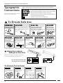
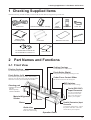
PC-50
USER'S MANUAL
For the USA
FEDERAL COMMUNICATIONS COMMISSION
RADIO FREQUENCY INTERFERENCE
STATEMENT
This equipment has been tested and found to comply with the
limits for a Class A digital device, pursuant to Part 15 of the
FCC Rules.
These limits are designed to provide reasonable protection
against harmful interference when the equipment is operated
in a commercial environment.
This equipment generates, uses, and can radiate radio
frequency energy and, if not installed and used in accordance
with the instruction manual, may cause harmful interference
to radio communications.
Operation of this equipment in a residential area is likely to
cause harmful interference in which case the user will be
required to correct the interference at his own expense.
NOTICE
Grounding Instructions
Do not modify the plug provided - if it will not fit the outlet,
have the proper outlet installed by a qualified electrician.
Check with qualified electrician or service personnel if the
grounding instructions are not completely understood, or if in
doubt as to whether the tool is properly grounded.
Use only 3-wire extension cords that have 3-prong
grounding plugs and 3-pole receptacles that accept the tool’s
plug.
Repair or replace damaged or worn out cord immediately.
Operating Instructions
KEEP WORK AREA CLEAN. Cluttered areas and benches
invites accidents.
Unauthorized changes or modification to this system can void
the users authority to operate this equipment.
DON’T USE IN DANGEROUS ENVIRONMENT. Don’t
use power tools in damp or wet locations, or expose them to
rain. Keep work area well lighted.
DISCONNECT TOOLS before servicing; when changing
accessories, such as blades, bits, cutters, and like.
The I/O cables between this equipment and the computing
device must be shielded.
REDUCE THE RISK OF UNINTENTIONAL STARTING.
Make sure the switch is in off position before plugging in.
USE RECOMMENDED ACCESSORIES. Consult the
owner’s manual for recommended accessories. The use of
improper accessories may cause risk of injury to persons.
NEVER LEAVE TOOL RUNNING UNATTENDED.
TURN POWER OFF. Don’t leave tool until it comes to a
complete stop.
For Canada
CLASS A
NOTICE
This Class A digital apparatus meets all requirements of the
Canadian Interference-Causing Equipment Regulations.
CLASSE A
AVIS
Cet appareil numérique de la classe A respecte toutes les
exigences du Règlement sur le matériel brouilleur du
Canada.
ROLAND DG CORPORATION
1227 Ohkubo-cho, Hamamatsu-shi, Shizuoka-ken, JAPAN 432
MODEL NAME
: See the MODEL given on the rating plate.
RELEVANT DIRECTIVE : EC MACHINERY DIRECTIVE (89/392/EEC)
EC LOW VOLTAGE DIRECTIVE (73/23/EEC)
EC ELECTROMAGNETIC COMPATIBILITY DIRECTIVE (89/336/EEC)
WARNING
This is a Class A product. In a domestic environment this product may cause radio interference in
which case the user may be required to take adequate measures.
Table of Contents
Thank you very much for purchasing the <Color CAMM> Model PC-50.
• To ensure correct and safe usage with a full understanding of this product's performance, please be sure to read through this
manual completely and store it in a safe location.
• Unauthorized copying or transferal, in whole or in part, of this manual is prohibited.
• The contents of this operation manual and the specifications of this product are subject to change without notice.
• The operation manual and the product have been prepared and tested as much as possible. If you find any misprint or error,
please inform us.
Table of Contents
Typographic Conventions ..........................................................................................................................2
To Ensure Safe Use ................................................................................................................2
About the Labels Affixed to the Unit ...............................................................2
To Ensure Correct Use .............................................................................................................................2
1 Checking Supplied Items ......................................................................................................................3
2 Part Names and Functions ...................................................................................................................3
2-1
Front View .......................................................................................................................................3
2-2
Rear View ........................................................................................................................................3
2-3
Operation Panel .............................................................................................................................4
3 Set-up and Connections .......................................................................................................................5
4 What the PC-50 Can Do .........................................................................................................................5
5 Basic Operation .......................................................................................................................................6
5-1
DIP Switch Settings .......................................................................................................................6
5-2
Powering On ...................................................................................................................................6
5-3
Installing/Removing a Blade .........................................................................................................7
5-4
Installing a Ribbon Cartridge ........................................................................................................ 8
5-5
Loading/Removing the Material ................................................................................................ 10
5-6
Downloading Printing/Cutting Data ...........................................................................................11
5-7
Pausing Operations ..................................................................................................................... 11
5-8
Moving the Base Point for Printing or Cutting ........................................................................ 12
5-9
Cutting Test to Check Cutter Force .......................................................................................... 12
5-10 Performing a Self-test ................................................................................................................ 13
5-11 Powering Off ................................................................................................................................ 13
6 To Perform Long Printing/Cutting ................................................................................................... 14
7 Printing and Cutting Samples .......................................................................................................... 15
8 About the Printing/Cutting Area ....................................................................................................... 16
9 About the Blade .................................................................................................................................... 17
10 Care and Maintenance ........................................................................................................................ 18
11 What to Do If... ...................................................................................................................................... 19
12 Specifications of PC-50 ...................................................................................................................... 22
Clipart used this manual is from CorelDRAWTM
Windows is a registered trademark or trademark of Microsoft Corporation in the United States and/or other countries.
Copyright © 1996 ROLAND DG CORPORATION
1
Typographic Conventions / To Ensure Safe Use
Typographic
Conventions
This manual uses typographic conventions
which are outlined at the right.
This indicates a point requiring particular care to ensure safe use of the product.
: Failure to heed this message will result in serious injury or death.
: Failure to heed this message may result in serious injury or death.
: Failure to heed this message may result in minor injury.
NOTICE
: Indicates important information to prevent machine breakdown or
malfunction and ensure correct use.
: Indicates a handy tip or advice regarding use.
To Ensure Safe Use
Never disassemble or
modify this product.
Do not allow liquids, metal
objects or flammables
inside the machine.
Fire or breakdown may result.
Handle the power cord with care.
Do not step on or damage the power
cord, or allow heavy objects to be placed
atop it. Failure to heed may result in
electrocution
or fire.
Do not install in an
unstable or high location.
Ensure the safety of the area
around the platen before
switching on the power.
The carriage moves simultaneously
when the power is switched on.
ON
Handle the blade
with care.
Do not install the machine on
the edge of a table, or it may
fall.
Do not inadvertently
allow the hands, hair, or
necktie near the carriage
while in operation.
About the Labels
Affixed to the Unit
These labels are affixed to the body of this product.
The following figure describes the location.
Do not allow the hands near
the platen while in operation.
To Ensure Correct Use
NOTICE
This product is a
precision instrument and
must be handled with
care.
NOTICE
Do not install in an area
subject to dust, high
humidity or poor
ventilation.
NOTICE
NOTICE
Do not connect to an AC
outlet that supplies other
than the specified
voltage.
100 V
117 V
220 V
When the unit is not in use
for an extended period,
detach the electrical plug
from the AC outlet.
3
2
240 V
2
When pulling the
power cord from an
electrical socket, be
sure to grip the plug.
240 V
1
Do not place hands
near the platen while
in operation.
1 Checking Supplied Items / 2 Part Names and Functions
1 Checking Supplied Items
Check the following to make sure that you received all the items that were shipped along with the unit.
Power Cord
Thermal transfer ribbon cartridge
Cleaning Sheet
for Printing Head
Roller Base
PC-50 DRIVER for windows 95
PC-50 DRIVER for windows 3.1
Blade
(Carbide)
Blade Holder
Material for Test Cuts
Cutter Tool
Head Cleaner
User's Manual
2 Part Names and Functions
2-1 Front View
Cutting Carriage
Printing Carriage
The blade holder is mounted here.
The ribbon cartridge is mounted here.
Pinch Roller (Right)
This presses the material against the grit roller.
Pinch Roller (Left)
Press material against the grit roller. When loading
material, place the left roller inside the left edge of the
material to correctly track it through the machine.
Cutter Force Control Slider
Sets the down force for the cutting tool.
DIP Switches
Used to make various settings.
Cleaning pad
* Please do not remove
this pad.
Removing it may
result in breakdown.
Serial (RS-232C)
Input Connector
Material Alignment
Sticker
In a serial configuration,
connect the serial cable
here. This cable carries
data to your computer.
Grit Roller
Parallel (Centronics) Input
Connector
Platen
In a parallel configuration, connect
the parallel cable here. This cable
carries data to your computer.
Guide Line
Align the material with
these lines when loading.
Operation Panel
3
2 Part Names and Functions
2-2 Rear View
Sheet Loading Lever
Used to raise or lower the pinch rollers
when loading or unloading material.
Power Switch
Guide Line
Align the material with
these lines when loading.
Power Connector (AC IN)
This connector accepts standard AC power cord.
2-3 Operation Panel
SETUP Key
SETUP LED
Lights when the SETUP key is pressed.
Operations can be performed when lighted.
PAUSE LED
Lights when the PAUSE key is pressed to stop
the PC-50 temporarily.
BASE POINT SET LED
Lights when the base point is set.
CHANGE LED
Flashes when the ribbon cartridge is being
changed.
Pressing this key after loading material detects
the position of the pinch rollers and automatically determines the area for printing or cutting.
Also, pressing this key after using the PAUSE
key to temporarily stop an operation in progress
will delete the data that has been sent to the PC50 from the computer. This key must be pressed
in order to begin printing or cutting.
PAUSE Key
When pressed once, this key temporarily halts
operation in progress. Pressing this key again
releases the paused state.
BASE POINT SET Key
Sets the current position of the blade to the
base point for printing or cutting.
BUSY LED
Flashes (orange) when while receiving data
from the computer, and lights (green) during
operation.
This goes dark when operation ends.
CLEANING Key
Cleans the printing head.
For more details, see "10 Care and
Maintenance."
TEST Key
Executes a cutting test to check material
characteristics, cut quality, and suitable
pressure for the blade.
POWER/ERROR LED
Lights when the power is switched on and
flashes when an error is generated.
4
CHANGE Key
Press this key after replacing the ribbon
cartridge.
The PC-50 checks to make sure the ribbon
cartridge has been changed, and printing
resumes.
(Cursor Keys)
Pressing the
,
,
, and
keys causes
the tool or material to move in the specified
direction.
3 Set-up and Connections / 4 What the PC-50 Can Do
The SETUP LED and POWER/ERROR LED blink simultaneously.
The SETUP LED and POWER/ERROR LED blink simultaneously if material is not loaded correctly. See “5-5 Loading/Removing
Material” for an explanation of how to load material.
The PAUSE LED and CHANGE LED blink simultaneously.
The PAUSE LED and CHANGE LED blink simultaneously if no ribbon cartridge is installed, or if the ink ribbon has run out. For more
details, see “5-4 Installing a Ribbon Cartridge.”
3 Set-up and Connections
When arranging setup space for the PC-50, make sure you have a space that is at least 950 mm (37-7/16") wide, 500 mm (19-11/16") in
depth, and 230 mm (9-1/16") in height. Since the material moves during printing and cutting, make sure the unit is placed on a stable,
sturdy surface. Also make sure there is nothing that can block the material at both front and rear.
NOTICE
• Avoid installing the PC-50 in the following conditions, as this may result in damage to the machine.
Avoid places subject to strong electrical noise.
Avoid excessively dusty or damp places.
Never leave the unit in a place that is subject to direct sunlight or extreme temperatures.
Because it is normal for this device to emit heat when in operation, never place it in an area with poor ventilation.
• Do not try to pick up or move the PC-50 by grasping the top area of the unit. Be sure to use both hands to grip the PC-50 securely
on the left and right sides.
• Always make sure that the power is off on both the computer and the PC-50 whenever any cables are connected or disconnected.
• Ensure that the power supply voltage in within ±10% of the machine's rated voltage.
Cables are available separately. One which you are sure matches
the model of computer being used should be selected.
Power outlet
Power
connector
Power cord
Serial interface cable
Serial connector
or
parallel connector
Parallel input connector
Serial input connector
Parallel interface cable
4 Here’s What the PC-50 Can Do
• Print color graphics on vinyl film and other materials.
• Custom cut vinyl film and other materials.
• Print color graphics on vinyl film and other materials, and then immediately custom cut the material.
5
5 Basic Operation
5 Basic Operation
5-1 DIP Switch Settings
DIP switch
Function
OFF
ON
SW-1
Baud rate
9600
19200
SW-2
Parity
Disable
Enable
SW-3
Parity
ODD
EVEN
SW-4
Handshake
Hardwire
XON/XOFF
SW-5
Front edge sense
Disable
Enable
SW-6
Cut sheet mode
Disable
Enable
SW-7
Blade offset
0.25
0.5*
SW-8
Long output mode
Light
Heavy
SW-9
Prefeed mode
Enable
Disable
SW-10
(Not Used)
–
–
NOTICE
DIP switches settings must be made only
when the power is turned off.
*This option should be selected only when you are using
optional blade, ZEC-U3050.
Please contact your dealer for more information.
All DIP switches are set to OFF when shipped from the factory.
The DIP switches are located on the right face of the unit, near the bottom.
SW-1–4 : Sets the communication parameters for a serial connection. When the PC-50 is connected to the computer through the serial
port, be sure that the communication parameters for SW-1 to SW-4 are set correctly, matching the computer port settings.
(Data length is fixed to 8 bits. It is automatically determined whether the number of stop bits is 1 or 2.)
SW-5
: Detects automatically the front edge of loaded material. To detect the front edge of loaded material, set SW-5 to ON (enabled).
SW-6 : Detects length of cut material automatically. Switch to ON (enabled) when loading sheet material, and OFF (disabled) when
loading roll material.
SW-7
: Sets the amount of offset for the cutter blade. Set to OFF when using a tool with a blade offset of 0.25 mm, or to ON when
using a tool with a blade offset of 0.5 mm.
SW-8 : Sets the weight of the material. SW-8, which controls the material weight, should normally be set to OFF (light). Cutting
speed slows down when switch is turned ON, but the force used to move the material and the blade increases.
SW-9
: Acclimates the machine and the material before cutting or printing, which can produce more attractive printing or cutting
results. This is normally set to OFF (enabled).
(When the cut-sheet mode (SW-6) is set to ON (enabled), the prefeed mode is disabled, regardless of the setting of SW-9.)
5-2 Powering On
Press the side of the
switch marked “ | ”.
6
When the power switch is pressed to power on the unit, the
tool carriage moves. Use caution to ensure that your hands or
other objects do not become caught in the moving parts.
5 Basic Operation
5-3 Installing/Removing a Blade
NOTICE
Do not touch the tip of the blade. This could impair the cutting performance of the blade.
Installation
1
Insert blade into the blade holder until it
snaps into place with an audible click.
2
2) Support the tool-securing screw from below and install the blade
holder.
* Insert the blade holder until the collar is flush with the carriage.
Push-pin
Cutting carriage
Blade holder
1) Loosen
3) Tighten
Blade
Tool-securing screw
Adjusting the
Cutter Blade
When stock vinyl film is to
be cut, tighten the cap all
the way (2.5 mm (about
0.1") of blade extension).
Tighten the cap until
gap is eliminated
Amount of cutter blade
extension: 2.5 mm (about
0.1") (maximum length)
Turn the cap as
shown by the arrow
Blade adjustment may be necessary when:
- cutting material whose carrier paper is thinner than the material itself
- cutting material with no carrier paper
1)
2)
Gap
Thickness of the
sheet portion
Amount of cutter blade
extension: 0 mm
Amount of cutter
blade extension
Turn the cap as
shown by the arrow
Turn the cap as shown by the
arrow to align the tip of the
blade with the tip of the cap
Thickness of the carrier paper
NOTICE
When cutting is performed after printing, the cap tip of the blade holder may scratch the printed surface. If this is the case,
lengthen the cutter blade extension.
Removal
1
2) Remove the blade holder from
the cutting carriage.
Cutting carriage
1) Loosen
Tool-securing screw
Leave the tool-securing screw loose. Tightening the screw makes
it more difficult to install the blade holder.
2
Push-pin
Blade holder
Press the push-pin and
remove the blade from
the blade holder.
Blade
If a blade was used, wipe the blade with a soft cloth to
remove any material that may cling to it.
7
5 Basic Operation
5-4 Installing a Ribbon Cartridge
NOTICE
• A used ribbon cartridge cannot be reused. Do not attempt to turn over and reinstall a used ribbon cartridge, or to rewind the ink
ribbon and reuse the cartridge.
• If a single-color ink ribbon has been used for printing, do not attempt to print overtop of this with a four-color ink ribbon or an ink
ribbon of a different color.
• Before starting to print, make sure that a ribbon cartridge of the desired color has been installed.
• If only cutting is to be performed, there is no need to install a ribbon cartridge.
Remove Excess Slack from the Ink Ribbon
2) Install the ribbon
cartridge.
Printing head
1) Open the
cover.
3) Close the
cover.
Take care to ensure
that the ink ribbon is
not pinched when the
cover is closed.
The ink ribbon may show some slack when the stopper
has been removed from the ribbon cartridge. If this is the
case, the slack should be taken up before the ribbon
cartridge is installed.
Ink ribbon
Use your finger or a
pen to take up excess
slack in the ink ribbon.
Take care to ensure that the ink ribbon
does not catch on the printing head.
Remove the stopper
If the ink ribbon runs out while printing
1) If the ink ribbon runs out during printing, operation stops.
The PAUSE LED and CHANGE LED will blink simultaneously.
2) Remove the old ribbon cartridge.
3) Install a new ribbon cartridge, then press the CHANGE key. (Be sure to install an ink ribbon of the same type as the old one.)
How to Perform Printing
Process Color Printing
Full-color printing is performed using the process colors CYAN (C), MAGENTA (M), YELLOW (Y), and BLACK (K).
The method used for printing depends on the type of cartridges that are installed.
When using a CR-4C ribbon cartridge
All four CMYK colors are contained in a single ribbon cartridge, so there is no need to change cartridges during printing.
The cartridge contains successive lengths of ribbon of each color.
If data is sent to the machine while a single-color ribbon cartridge is installed, the carriage specifies "SPECIAL COLOR" and stops.
When this happens, replace the cartridge to CR-4C and press the CHANGE key.
When using CR-CY, MG, YE, and BK ribbon cartridges
During printing, the single-color ribbon cartridges are manually changed according to the color required. This method is more
economical than using the CR-4C, because no portions for ink ribbons are wasted. CR-CY, MG, YE, and BK ribbon cartridges are
sold separately.
8
5 Basic Operation
When CR-CY, MG, YE, and BK ribbon cartridges are used for printing, the PC-50 performs printing in the following color sequence:
MAGENTA (M)
CYAN (C)
BLACK (K)
YELLOW (Y)
Follow the steps below to install and change the ribbon cartridges.
1
When data is sent, the
carriage first specifies
MAGENTA and stops.
The CHANGE LED
blink
2
3
First install the MAGENTA
(CR-MG) ribbon cartridge.
MAGENTA
(CR-MG)
Press the CHANGE key.
When the MAGENTA
printing is finished, the
carriage indicates the next
color (CYAN) and stops.
The CHANGE LED
blink
4
5
Replace the MAGENTA (CRMG) cartridge with the CYAN
(CR-CY) cartridge, then press
the CHANGE key.
CYAN
(CR-CY)
When the CYAN printing is
finished, the carriage indicates
the next color (BLACK) and
stops.
The CHANGE LED
blink
6
Use the same procedure to change to the BLACK (CR-BK) and YELLOW (CR-YE) ribbon cartridges.
* If any of the four colors (C, M, Y, or K) is not used, the PC-50 does not stop at that color.
Special color Printing
This is used to add emphasis to some areas, or when printing with limited colors. Special-color ribbon cartridges are sold separately.
When the ribbon cartridge needs to be changed, the carriage stops at SPECIAL COLOR.
For more details, please refer to the operator's manual for the software driver, or to online help.
9
5 Basic Operation
5-5 Loading/Removing the Material
Loading the Material
Material with a width (horizontal dimension) of 279.4 mm (11") to 482.6 mm (19") can be loaded.
Any length (vertical dimension) of 110 mm (4-3/8") or more is acceptable.
• The tool carriage moves when the SETUP key is pressed. Take care to ensure that your hands or other objects do not
get caught in the moving parts.
• A soiled material may impair printing accuracy. If dirt or oils from the hand are transferred to the material when it is
loaded, use a cloth moistened with alcohol to wipe the material clean before printing.
NOTICE
Never move the tool carriage by hand. Damage and poor performance may result.
1
1) Raise the sheet loading lever.
2) Move the right-hand pinch roller
until it makes contact.
3) Pass the material between
the pinch rollers and the
grit roller.
Guide lines
5) Move the pinch roller to the
left-hand edge of the
material.
Inner side of
the material
4) Right side of the material to
be placed at front and rear
guide lines.
* Before attempting to move the pinch roller,
be sure to raise the sheet loading lever.
When using roll material
1) Load roll material on the sheet base included
with the PC-50.
Roll material
3) Pass the end of the material
between the pinch rollers and
the grid rollers so that it extends
from the front of the unit.
Front
Pull out the amount of roll
material to be used.
Roller base
Rear
2) Gently press the roll material against the rear surface
of the unit as shown in the figure.
2
Lower the sheet loading levers to secure the material in place.
3
Press the SETUP key.
Sheet loading lever
The SETUP LED
lights up
10
5 Basic Operation
Removal
1
2
Press the SETUP key.
Raise the sheet loading lever.
The SETUP LED
goes out
The carriages moves to the left edge of
the printing/cutting area.
Use the separate blade included with the
PC-50 to cut the material off of the roll.
5-6 Downloading Printing/Cutting Data
The unit will begin printing/cutting when it receives printing/cutting data sent from the computer.
For further details, refer to the user's manual provided with your software.
5-7 Pausing Operations
If you want to stop the PC-50 momentarily while it is printing or cutting, follow the procedure described below.
1
Press the PAUSE key.
The PAUSE LED
lights up
Printing or cutting is paused.
2
To resume printing or cutting
To Terminate printing or cutting
Press the PAUSE key.
1) Halt transmission of printing or cutting instructions
from the computer.
2) Press the SETUP key.
The PAUSE LED
goes out
Printing or cutting is resumes.
The SETUP LED goes out
Printing or cutting instructions already sent
from the computer to the PC-50 are deleted,
and operation stops.
11
5 Basic Operation
5-8 Moving the Base Point for Printing or Cutting
The BASE POINT SET key can be used to move the base point for printing or cutting.
Use all areas of the material effectively, without waste.
1
The carriage moves to the new base point.
2
< Example >
Press the BASE POINT SET key.
NEW BASE POINT
The BASE POINT SET
LED lights up
*If the base point has been
moved, the sheet-width value
for the Windows driver should
be entered again.
If this value is not corrected,
output results may be cut off
before reaching their normal
end.
Rear
Front
H
W
Enter this value
NEW BASE POINT
5-9 Cutting Test to Check Cutter Force
Before cutting, you may wish to perform a “cutting test” to learn whether the unit cut satisfactorily. If cutting is to be continued on the
same material, there is no need to perform a cutting test.
Move the cutter force control slider all the way to the left (minimum cutter force).
1
Use the , , , and
keys to move the tool
carriage to the position on
the material where the
cutting test is to be executed.
* Note that an area of approximately 2 square centimeters (a little less than a square inch) is
required to make a test cut.
3
1) First peel off the round section (shaded as shown ).
When it can be peeled by itself, without disturbing the square, the cutter force is set
appropriately.
2) Next, peel off the square, and look at the backing behind it.
The optimum blade pressure is correct if you can clearly make out the lines left by the blade.
Adjust the cutter force control slider until results as shown above are obtained.
(Gradually increase the cutter force until you reach the optimum level.)
12
2
Press the TEST key.
Cutting test starts.
Peel off first
Then peel
this off
Origin (when
using roll material)
5 Basic Operation
5-10 Performing a Self-test
The PC-50 is equipped with a “self-test” function to allow you to check whether or not it is capable of operating normally. If the PC-50 is
not performing correctly, follow the steps below to perform a self-test.
A computer is not required in order to carry out the self-test.
1
3
Install a blade and ribbon cartridge
in the PC-50.
Performing a cutting test.
Load the material, and press the SETUP key.
Operations is normal if the figure shown at below.
2
Hold down the
key on the panel
while you turn the power on.
+
5-11 Powering Off
NOTICE
• Do not switch off the power while the printing head is lowered.
Doing so may damage the head and impair printing performance.
Ribbon cartridge
Printing head is lowered
Platen
• When the unit is not in use, keep the pinch rollers raised. The pinch rollers may be deformed if left engaged.
• If you do not intend to use the unit for an extended period of time, disconnect the unit from the power outlet.
Press the side of
the switch marked
with “
”.
When the SETUP key is pressed to release
the setup state, the carriage moves to the
position shown in the figure, then stops.
Switch off the power when the carriage is at
this position.
Carriage position when
switching off the power
13
6 To Perform Long Printing/Cutting
6 To Perform Long Printing/Cutting
When performing printing or cutting over a length of 1.5 m (60") or more, first feed out the required length of material. Then
follow the steps below to load the material.
4
1
Pull out the material from the roll and
pass it through the unit.
Pull out the amount of
roll material to be used.
Use material that is wider by 50 mm (2") or more than
the width of the printing or cutting to be performed.
3
Guide line
25 mm
(1")
or more
2
Material
alignment
stickers
25 mm
(1")
or more
Guide line
5
Press the SETUP
key.
6
Feed out the length
of material to be
printed or cut.
Make sure that the material
remains held by the pinch
rollers.
If the material does come
loose from the pinch rollers,
set it in place again.
14
7
8
Material
alignment
stickers
Return the fed-out
material.
After finishing the
setup for the material,
send the data from
the computer.
7 Printing and Cutting Samples
7 Printing and Cutting Samples
Removing the blank space surrounding a picture
Cutting outline
Material
Stick
Adding color to a border
Cutting outline
Stick
Material
Correcting Line Pitch
Line pitch: Correct
Line pitch is too narrow, and ink
overlaps.
Line pitch is too wide, and spaces
appear between lines.
Line-pitch correction:
Set to “Wide” or “Extra Wide”
Line-pitch correction:
Set to “Narrow” or “Extra Narrow”
How to Correct Line Pitch
Hold down the SETUP key and switch on the
power.
Pressing the
or
key changes the pattern
in which the PAUSE LED, BASE POINT SET
LED, and CHANGE LED light up. This
pattern indicates the current line pitch. Use
the table at right as a reference to press the
and
keys and make the desired line-pitch
setting. After making the setting, press the
SETUP key (the SETUP LED will light up).
(If material is not loaded, be sure to load one
before pressing the SETUP key.) The setting
that has been made is stored in memory even
after the power is switched off. To change the
setting, simply repeat the procedure just
described.
* Distance accuracy cannot be guaranteed when
line-pitch correction has been performed.
Line-pitch Extra wide
correction
LED
display
pattern
Wide
Default
(no correction)
Narrow
Extra narrow
Lighted
Blinking
Dark
Dark
Dark
Dark
Blinking
Lighted
Blinking
Dark
Dark
Dark
Dark
Blinking
Lighted
15
7 Printing and Cutting Samples / 8 About the
Printing/Cutting Area / 9 About the Blade
Printing with a width of 210 mm or more (using a 4-color ribbon cartridge)
210 mm (8-1/4") (length of the ink ribbon)
OK
No good
Ink-ribbon seam
Take steps to ensure that the
printing data does not overlap
with the ink-ribbon seam
8 About the Printing/Cutting Area
Factory default
When DIP switch SW-5 (front
edge sense) is ON (enabled)
Pinch roller (left)
Pinch roller (left)
Pinch roller
(left)
12.5
mm
(1/2")
6.5 mm
(5/16")
25 mm (1") or more
When DIP switch SW-6 (cut
sheet mode) is ON (enabled)
50 mm (2")
12.5
mm
(1/2")
6.5 mm
(5/16")
110 mm (4-3/8")
or more
25 mm (1")
12.5
mm
(1/2")
..... Printing/Cutting area
6.5 mm
(5/16")
25 mm (1")
9 About the Blade
If the blade becomes dull
When the blade starts to lose its sharpness, try gradually increasing the cutter force.
Increasing the cutter force temporarily allows the blade to perform better. However, once the blade is dull, it is time to replace it.
Average blade life
The life of a blade varies, depending on the amount of cutting it performs.
The total cutting length can vary considerably, depending on the thickness, toughness, and type of adhesive of the cut material. Set an
appropriate cutter force, one that is well matched to the material and the hardness of the blade. This will extend the life of the blade.
Excessive cutter forces can cause the blade to wear out quickly. Care should be taken.
16
10 Care and Maintenance
10 Care and Maintenance
Cleaning the printing head
Before performing printing, clean the printing head. In order to maintain attractive image quality, we recommend
performing cleaning each time printing has been carried out. Ordinary soiling can be removed using the method
described here. If soiling is severe, remove it by performing cleaning with a cleaning sheet.
1
2
TAKE OUT
the ink-ribbon
cartridge
REMOVE
the blade holder
Pressing the CLEANING key has
no effect if an ink cartridge is
installed.
Remove the ink cartridge before
pressing the key.
3
Press the
CLEANING key
Head cleaning is finished when the
carriage stops moving.
The Cleaning Pad
If the cleaning pad on the left edge of the unit's front surface is damaged, the printing head may be destroyed. If the cleaning pad is
damaged by a blade or the like, please contact your authorized Roland DG Corp. dealer or service center. (This pad replacement is a
charged service.)
17
10 Care and Maintenance
Cleaning with cleaning sheet
Soiling which cannot be removed by ordinary cleaning is removed using a cleaning sheet.
NOTICE
• Do not use any cleaning sheet that has a damaged surface such as cuts, tears or creases.
• The printing head can be damaged by dust.
• The Pinch rollers should be set over the black bands at either end of the sheet, to ensure that the head is
restricted to the center cleaning area of the sheet and cannot pass over marks left by the pinch rollers.
• Store the cleaning sheet in a clean place and wipe the cleaning surface with a "lint free" cloth before use.
1
TAKE OUT
the ink-ribbon
cartridge
2
REMOVE
the blade holder
3
5
Set the Right Hand
pinch roller to the right
hand limit of its travel
Keep pushing
the CLEANINIG key,
and switch on
the power
4
LOAD
the cleaning sheet
Press the SETUP key
6
Lower the sheet loading levers to secure
the material in place.
Matt face is up side
Head cleaning is finished when the
carriage stops moving.
Position of the sheet and pinch rollers (levers)
shown from the top
Pinch rollers (levers)
Grit roller
This is the side of the cleaning surface (non glossy surface)!
Right side of
the sheet to be
placed at front
and rear guide
lines
光沢の無い面がクリーニング面です。
Cleaning sheet
7
18
After cleaning has finished, switch off the power and remove the sheet.
10 Care and Maintenance / 11 What to Do If...
NOTICE
• Be sure to switch off the power to the PC-50 before cleaning the unit or platen or
before using head cleaner to clean the printing head.
• Never attempt to oil or lubricate the mechanism.
Cleaning with head cleaner
Printing head
NOTICE
Drops of cleaning fluid may spray out when the cap is opened. Hold away from the
platen when opening the cap. The platen may be discolored by any cleaning fluid
that comes in contact with it. (The cleaning fluid is non-toxic.)
Open the cover and remove the ribbon cartridge.
To remove any soiling on the printing head, use a head cleaner included with the PC-50.
After cleaning, refer to “5-10 Performing a Self-test” to check operation and make
sure that the PC-50 is working correctly.
Cleaning the main unit
For routine cleaning, use a soft piece of cloth.
Head cleaner
Cleaning the platen
If the platen becomes soiled, wipe it clean with a dry, soft cloth.
Do not wipe with a head cleaner or alcohol.
Use care when cleaning to avoid damaging the surface of the platen. Damage to the platen may impair the accuracy of printing.
11 What to Do If...
If you want to completely stop the operation of the PC-50, turn off the power switch.
If the PC-50 doesn't run...
Turn on the power. (See “5-2 Powering On” .)
Is the unit in SETUP status (the
SETUP LED is lit)?
If the SETUP LED is not illuminated, make sure the material is loaded correctly
and press the SETUP key to illuminate the SETUP LED.
Is the PAUSE LED illuminated?
If the PAUSE key has been pressed and the PAUSE LED is lighted, the unit has
been paused (see “5-7 Pausing Operations” ).
To resume printing or cutting, press the PAUSE key again. The PAUSE LED is
extinguished, and printing or cutting resumes.
To terminate printing or cutting, first stop the transmission of printing or cutting
instructions from the computer to the PC-50. Then press the SETUP key. This
deletes the printing or cutting instructions that have already been sent from the
computer to the PC-50, and printing or cutting is stopped.
If operation is still not correct when the next batch of data is sent after printing or
cutting, or cutting has been stopped, switch the power off and then on again.
If connected via the serial port, do the
communication parameters for the
PC-50 match those of the computer?
Set the DIP switches correctly (see “5-1 DIP Switch Settings” .)
Is the computer set up correctly?
Check the following items:
• DIP switches
• Memory switches • Interface board
• Communication parameters
• Other settings
Read the computer user’s manual and set it up correctly.
Computer
PC-50
Is the PC-50 power on?
19
Software
Connection cable
11 What to Do If...
Are the computer and the PC-50
linked with the right cable?
The type of cable you need is determined by your computer and the software you
are using. Even if the computer is the same, running different software may require
a different cable. Use the cable specified in your software.
Is the cable making a secure connection?
Connect securely. (See “3 Set-up and Connections” .)
Is the OS set up correctly?
Check the following items:
• Output port selection
• Output device selection
• Output port open
• Communication parameters
• Other settings
Check the OS user’s manual and set it up correctly.
Are the application software settings
correct?
Check the following items:
• Output device specifications (select a device name that matches the instruction system. If the wrong device is selected an incorrect instruction may be
output, resulting in an error).
• Communication parameters
• Other settings
Check the software user’s manual and set it up correctly.
Are the settings for the driver software
correct?
If you are using driver software for output on the PC-50, then make the settings for
the correct driver in the computer. Select the PC-50 as the output device.
Clean, attractive printing is impossible
Is there faint soiling around printed areas?
Especially when using a single-color ribbon, faint soiling is seen in areas where
there is no printing. When this occurs, use alcohol to wipe away soiling on the
sheet immediately after printing.
Is the printing head dirty?
Clean the printing head (see “10 Care and Maintenance”).
NOTICE
If cleaning will not improve the printing quality, the printing head might
reach to the end of its life.
Contact your dealer for replacement of the printing head.
Is the surface of the platen dirty or
scratched?
Clean the platen (see “10 Care and Maintenance”).
Is the material dirty?
Remove superficial soiling, then load the material.
Is the material damaged?
Clean, attractive printing is not possible if the material is damaged or warped.
Use care to keep materials from being damaged while in storage.
Has the material been sufficiently acclimated before use?
The material may shrink or expand due to absorption of moisture in the air. If
such shrinking or expansion occurs during printing, the printed pattern may be
misaligned.
Pull out the amount of roll material to be used, and allow to stand for 30 minutes
to an hour.
The amount of time required for acclimation varies according to the type of
material.
Is the cleaning pad free of dust or damage?
A dusty or damaged cleaning pad may destroy the printing head. Gently wipe
away any adhering dust or grime.
If the cleaning pad is damaged by a blade or the like, please contact your
authorized Roland DG Corp. dealer or service center. (This pad replacement is a
charged service.)
20
11 What to Do If...
The Material is not cut properly
Are the blade and blade holder installed
correctly and securely?
Install these so that there is no looseness (see “5-3 Installing/Removing a Blade” ).
Is the blade chipped?
If it is, replace it with a new one (see “5-3 Installing/Removing a Blade” ).
Check if there are any dirty deposits on the
blade.
If dirty, remove and clean the blade.
Make sure you are using an appropriate
cutter force setting.
Perform a “cutting test,” then adjust the cutter force slider as necessary to obtain
the optimum cutter force (see “5-9 Cutting Test to Check Cutter force”).
When cutting a thick material, set DIP switch SW-7 to ON (heavy). (See “5-1 DIP Switch Settings” .)
The material slips away from the pinch rollers during operation
Are the sheet loading levers lowered?
If the sheet loading levers are raised, then make sure the left and right pinch rollers
are within the edged of the material and lower the sheet loading levers. (See “5-5
Loading/Removing the Material” .)
Make sure the material is parallel with the grit roller.
If the front edge of the material rests at an angle, cut off the odd-shaped part to make it straight. Then align it so that it is parallel with
the grit roller.
If the material is to be advanced over a long distance, moving the movable pinch roller inward slightly can help prevent the material
from becoming dislodged. Also, after loading the material, it is recommended that you carry out an alignment test by using the
key to advance the material by the amount that will be used for printing or cutting. Make sure that the material travels correctly
through the machine.
If roll material is used, print or cut only after first pulling out the amount of material that is to be used. The PC-50 is not designed to
pull material off rolls.
Make sure that the left and right edges of the material do not touch the inner surfaces of the PC-50 during operation. Such contact
may damage the material, and could also make it impossible to advance the material–thus causing it to slip.
The POWER/ERROR LED is blinking
Are the application software settings
correct?
Check the following items:
• Output device specifications (select a device name that matches the instruction system. If the wrong device is selected an incorrect instruction may be
output, resulting in an error).
• Communication parameters
• Other settings
Check the software user’s manual and set it up correctly.
If connected via the serial port, do the
communication parameters for the PC-50
match those of the computer?
Set the DIP switches correctly (see “5-1 DIP Switch Settings” .)
PAUSE LED and CHANGE LED blink simultaneously
Has the ink ribbon been used up?
If there is no more ink ribbon left for printing, replace the ribbon cartridge with a
new one (see “5-4 Installing a Ribbon Cartridge”).
SETUP LED and POWER/ERROR LED blink simultaneously
Is the material loaded correctly?
Load the material correctly (see “5-5 Loading/Removing the Material”).
Does the front of the material stick out to
the front surface of the PC-50?
Is the length of the loaded material too
short?
21
12 Specifications of PC-50
12 Specifications of PC-50
PC-50
Mechanism
Media-movement method, thermal transfer printing
Acceptable Media Width
Maximum Work Area
279.4 mm—482.6 mm (11"—19")
457.2 mm x 24,998 mm (18"—82'1/8")
Acceptable Media Type
Adhesive vinyl, thickness 0.06 mm—0.15 mm (0.00236"—0.00591")
Tools
Cutter: blade & blade holder.
Printing ribbon: thermal transfer ribbon cartridge.
Cutter Force
Cutting Speed
30 gf—200 gf
10 mm/sec.—400 mm/sec.(0.393"/sec—15.748"/sec)
Printing Speed
130 mm/sec. (5.118"/sec)
Cutting Resolution (Software Resolution)
Printing Resolution
Cutting Accuracy (Distance Accuracy)
Registration Between Printing & Cutting
0.025 mm/step (0.000984"/step)
360 dpi
Less than ±0.2 % of distance traveled or ±0.2 mm (±0.00788"), whichever is greater
Less than ±0.3 mm (±0.0118") (Excluding expansion or contraction of the media,
and excluding times when material is been reloaded)
Parallel (Centronics), Serial (RS-232C)
(The data received first after switching on the power is used to determine automatically
whether the parallel or serial interface is being used.)
1 Mb
SETUP, PAUSE, BASE POINT SET, CHANGE, CLEANING, TEST,
Interface
Memory
Control Switches
,
LED
Power consumption
Acoustic noise level
Dimensions
Weight
Operating Temperature
Operating Humidity
Accessories
,
,
POWER/ERROR, SETUP, PAUSE, BASE POINT SET, CHANGE, BUSY
1.0 A/110 V, 1.0 A/117 V, 0.5 A/220 V, 0.5 A/230 V, 0.5 A/240 V
Printing/Cutting mode: less than 68 dB (A)
Standby mode: less than 40 dB (A)
(According to ISO 7779)
840 mm (W) x 278 mm (D) x 227 mm (H)
(33-1/8" (W) x 11" (D) x 8-15/16" (H))
16 kg (35.3 lb.)
10—30°C (50—86°F)
35%—70% (non-condensing)
Power Cord, Thermal transfer ribbon cartridge, Blade (Carbide), Blade Holder, Cutter Tool,
Cleaning Sheet for Printing Head, Roller Base, Material for Test Cuts, Head Cleaner,
PC-50 DRIVER for windows 95, PC-50 DRIVER for windows 3.1, User's Manual
Interface Specifications
[Parallel]
Standard
Input Signals
Output Signals
Level of Input/Output Signals
Transmission Method
In compliance with the specifications of Centronics
STROBE (1 BIT), DATA (8 BIT)
BUSY (1 BIT), ACK (1 BIT)
TTL level
Asynchronous
[Serial]
Standard
Transmission Method
Transmission Speed
Parity Check
Data Bits
Stop Bits
RS-232C specifications
Asynchronous, duplex data transmission
9600, 19200 (Selected using DIP switches.)
Odd, Even, or None (Selected using DIP switches.)
8 bits (fixed)
1 or 2 bits (automatic discrimination)
22
(in all directions)
R4-971015