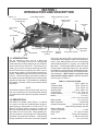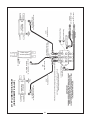
1
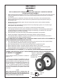
BUSH HOG
®
Model 2715 / 2710
Flex-Wing Rotary Cutter
Operator’s Manual
ASSEMBLY l OPERATION l MAINTENANCE
06/09 Rev. 1
$4.00
50054473
CONGRATULATIONS!
You have invested in the best implement of its type on the market today.
The care you give your Bush Hog implement will greatly determine your satisfaction with its performance and its service life. We urge a careful study of this manual to provide you with a thorough understanding of your new implement before operating, as well as suggestions for
operation and maintenance.
If your manual should become lost or destroyed, Bush Hog will be glad to provide you with
a new copy. Order from Bush Hog, 2501 Griffin Ave., Selma, Alabama 36703. Most of our manuals can also be downloaded from our website at www.bushhog.com
As an authorized Bush Hog dealer, we stock genuine Bush Hog parts which are manufactured
with the same precision and skill as our original equipment. Our trained service personnel are
well informed on methods required to service Bush Hog equipment,and are ready and able to
help you.
Should you require additional information or assistance, please contact us.
YOUR AUTHORIZED
BUSH HOG DEALER
BECAUSE BUSH HOG MAINTAINS AN ONGOING PROGRAM
OF PRODUCT IMPROVEMENT, WE RESERVE THE RIGHT
TO MAKE IMPROVEMENTS IN DESIGN OR CHANGES IN
SPECIFICATIONS WITHOUT INCURRING ANY OBLIGATION
TO INSTALL THEM ON UNITS PREVIOUSLY SOLD.
BECAUSE OF THE POSSIBILITY THAT SOME PHOTOGRAPHS IN THIS MANUAL WERE TAKEN OF PROTOTYPE
MODELS, PRODUCTION MODELS MAY VARY IN SOME DETAIL. IN ADDITION, SOME PHOTOGRAPHS MAY SHOW
SHIELDS REMOVED FOR PURPOSES OF CLARITY. NEVER
OPERATE THIS IMPLEMENT WITHOUT ALL SHIELDS IN
PLACE.
2715 ROTARY CUTTER
TABLE OF CONTENTS
SECTION/PARA
PAGE
Warranty ................................................2
Dealer Preparation Check List ...............3
Safety Precautions.................................4
Federal Laws and Regulations ..............5
I. INTRODUCTION & DESCRIPTION ......6
1-1 Introduction ......................................6
1-2 Description.......................................6
Key Operation Points .............................8
II. PREPARATION FOR USE ....................9
2-1 Attaching To Tractor .......................9
2-2 Optional Valve Mounting
Bracket Installation ........................10
2-3 Pitch Adjustment............................11
2-4 Wing Adjustment............................12
III.OPERATING INSTRUCTIONS............12
3-1 General Safety...............................12
3-2 Transporting...................................12
3-3 Operation .......................................13
SECTION/PARA
PAGE
IV. MAINTENANCE ..................................13
4-1 Maintenance Check List ................13
4-2 Lubrication .....................................14
4-3 Blade Replacement .......................16
4-4 Slip Clutch Operational Check.......19
4-5 Slip Clutch Adjustment...................19
4-6 Troubleshooting .............................19
V. ASSEMBLY..........................................20
5-1 Model 2515 Assembly ...................20
5-2 Model 2710 Assembly ...................24
5-3 Safety Chains Installation ..............25
5-4 Band Installation ............................26
5-5 Front Belting ..................................26
5-6 Hydraulic Plumbing........................26
5-7 Baffle Installation ...........................26
Hydraulic Diagrams..............................28
Safety Decals.......................................30
Torque Specifications ..........................32
RETAIL CUSTOMER’S RESPONSIBILITY
UNDER THE BUSH HOG WARRANTY
It is the Retail Customer and/or Operator’s responsibility to read the Operator’s Manual, to operate, lubricate, maintain and store the product in accordance with all instructions and safety
procedures. Failure of the operator to read the Operator’s Manual is a misuse of this equipment.
It is the Retail Customer and/or Operator’s responsibility to inspect the product and to have any
part(s) repaired or replaced when continued operation would cause damage or excessive wear
to other parts or cause a safety hazard.
It is the Retail Customer’s responsibility to deliver the product to the authorized Bush Hog
Dealer, from whom he purchased it, for service or replacement of defective parts which are covered by warranty. Repairs to be submitted for warranty consideration must be made within
forty-five (45) days of failure.
It is the Retail Customer’s responsibility for any cost incurred by the Dealer for traveling to or
hauling of the product for the purpose of performing a warranty obligation or inspection.
1
LIMITED WARRANTY
OOOOOOOOOOOOOOOOOOOOOOOOOOOOOOO
Bush Hog warrants to the original purchaser of any new Bush Hog equipment, purchased from an authorized Bush Hog dealer, that the equipment be free from defects in material and workmanship for a period of
one (1) year for non-commercial, state and municipalities’ use and ninety (90) days for commercial use from date
of retail sale. Model 2715 / 2710 gearboxes are covered by a five (5) year limited warranty period. The obligation
of Bush Hog to the purchaser under this warranty is limited to the repair or replacement of defective parts.
Replacement or repair parts installed in the equipment covered by this limited warranty are warranted for
ninety (90) days from the date of purchase of such part or to the expiration of the applicable new equip-ment warranty period, whichever occurs later. Warranted parts shall be provided at no cost to the user at an authorized Bush
Hog dealer during regular working hours. Bush Hog reserves the right to inspect any equipment or parts which
are claimed to have been defective in material or workmanship.
DISCLAIMER OF IMPLIED WARRANTIES & CONSEQUENTIAL DAMAGES
Bush Hog’s obligation under this limited warranty, to the extent allowed by law, is in lieu of all warranties, implied
or expressed, INCLUDING IMPLIED WARRANTIES OF MERCHANTABILITY AND FITNESS FOR A PARTICULAR PURPOSE and any liability for incidental and consequential damages with respect to the sale or use of the
items warranted. Such incidental and consequential damages shall include but not be limited to: transportation
charges other than normal freight charges; cost of installation other than cost approved by Bush Hog; duty; taxes;
charges for normal service or adjustment; loss of crops or any other loss of income; rental of substitute equipment,
expenses due to loss, damage, detention or delay in the delivery of equipment or parts resulting from acts beyond
the control of Bush Hog.
THIS LIMITED WARRANTY SHALL NOT APPLY:
1. To vendor items which carry their own warranties, such as engines, tires, and tubes.
2. If the unit has been subjected to misapplication, abuse, misuse, negligence, fire or other accident.
3. If parts not made or supplied by Bush Hog have been used in connection with the unit, if, in the sole judgement of Bush Hog such use affects its performance, stability or reliability.
4. If the unit has been altered or repaired outside of an authorized Bush Hog dealership in a manner
which, in the sole judgement of Bush Hog, affects its performance, stability or reliability.
5. To normal maintenance service and normal replacement items such as gearbox lubricant, hydraulic fluid,
worn blades, or to normal deterioration of such things as belts and exterior finish due to use or
exposure.
6. To expendable or wear items such as teeth, chains, sprockets, belts, springs and any other items that in the
company’s sole judgement is a wear item.
NO EMPLOYEE OR REPRESENTATIVE OF BUSH HOG IS AUTHORIZED TO CHANGE THIS LIMITED WARRANTY IN ANY WAY OR GRANT ANY OTHER WARRANTY UNLESS SUCH CHANGE IS MADE IN WRITING
AND SIGNED BY BUSH HOG’S SERVICE MANAGER, 2501 GRIFFIN AVE., SELMA, ALABAMA 36703.
OOOOOOOOOOOOOOOOOOOOOOOOOOOOOOO
Record the model number, serial number and date
purchased. This information will be helpful to your
dealer if parts or service are required.
MODEL NUMBER
MAKE CERTAIN THE WARRANTY INFORMATION
HAS BEEN FILED ONLINE WITH BUSH HOG
SELMA, ALABAMA
SERIAL NUMBER
DATE OF RETAIL SALE
2
DEALER PREPARATION CHECK LIST
2715 / 2710 ROTARY CUTTER
BEFORE DELIVERING MACHINE — The following check list should be completed.
Use the Operator’s Manual as a guide.
r
r
r
r
r
r
r
r
r
1.
Assembly completed.
2.
Gearbox filled with oil.
3.
All fittings lubricated.
4.
All shields in place and in good condition.
5.
All fasteners torqued to specifications given in Torque Chart.
6.
Slip clutches have been checked for proper operation.
7.
All decals in place and readable. (See decal page.)
8.
Overall condition good (i.e. paint, welds)
9.
Operators manual has been delivered to owner and he has been instructed
on the safe and proper use of the cutter.
r
r
10. Warranty information has been filed online with Bush Hog.
r
12. Purchaser or dealer elects to delete tow chain.
11. Purchaser or dealer elects to delete deflectors. (front belting, rear bands, front
and rear chains)
Explanation:
Explanation:
WARNING
For Non-Agricultural use, OSHA, ASAE, SAE and ANSI standards require the use of Chain Guards or
other protective guards at all times. Bush Hog strongly recommends the use of such guards for Agricultural uses as well, to reduce the risk of property damage, serious bodily injury or even death from objects
thrown out by or from contact with the cutting blades.
Dealer’s Signature
Purchaser’s Signature
THIS CHECKLIST TO REMAIN IN OWNER’S MANUAL
It is the responsibility of the dealer to complete the procedures listed
above before delivery of this implement to the customer.
3
IMPORTANT SAFETY PRECAUTIONS
This symbol is used to call attention to safety
precautions that should be followed by the operator to avoid accidents. When you see this
symbol, carefully read the message that follows
and heed its advice. Failure to comply with
safety precautions could result in serious bodily injury.
In addition to the design and configuration of equipment, hazard control and accident prevention are
dependent upon the awareness, concern, prudence and proper training of personnel in the operation, t r a n s port, maintenance and storage of equipment. Lack of attention to safety can result in accident, personal injury,
reduction of efficiency and worst of all—loss of life. Watch for safety hazards and correct deficiencies promptly.
Use the following safety precautions as a general guide to safe operations when using thismachine. Additional
safety precautions are used throughout this manual for specific operating and maintenance procedures. Read this
manual and review the safety precautions often until you know the limitations.
1.
Read the Operator’s Manual. Failure to read the Operator’s Manual is considered a misuse of this equipment.
2.
Become familiar with all the machine’s controls and all the caution, warning and danger decals affixed to the
machine before attempting to start or operate.
3.
Before starting or operating the machine, make a walk around inspection and check for obvious defects
such as loose mounting bolts and damaged components. Correct any deficiency before starting.
4.
Do not allow children to operate the cutter. Do not allow adults to operate it without proper instruction.
5.
Do not carry passengers.
6.
Keep the area of operation clear of all persons, particularly small children and pets. The operator should
cease mowing whenever anyone comes within the operating area.
7.
Clear the work area of objects which might be picked up and thrown.
8.
Use a piece of cardboard or wood rather than hands to search for hydraulic leaks. Escaping hydraulic oil
under pressure can penetrate skin. If fluid is injected into the skin, it must be surgically removed within a
few hours by a doctor familiar with this form of injury or gangrene may result.
9.
Do not operate without all guards and shields in place and in good condition.
10. Lower implement to ground, stop tractor engine, apply parking brake, and allow blades to completely stop
before leaving the tractor.
11. Keep hands and feet away from blades.
12. This cutter is not to be operated along highways or in any area where people may be present unless all
sides of the unit are enclosed by permanent bands, safety chains or other factory approved safety shields that
are in good repair.
13. Wear personal protective equipment such as, but not limited to, protection for eyes, ears, feet, hands and
head when operating or repairing the equipment. Do not wear loose clothing or jewelry that may catch on
equipment moving parts.
14. When performing adjustments or maintenance on the cutter, first lower it to the ground or block it securely at a
workable height.
15. Never stand between tractor and cutter while tractor is being backed to the cutter hitch.
16. Reduce speed when transporting cutter to avoid bouncing and momentary loss of steering.
17. Use tractor flashing warning lights, day or night, when transporting cutter on road or highways unless prohibited by law.
18. Stand clear of wing(s) when raising or lowering.
19. Purge air from hydraulic system before attempting to raise or lower wings.
20. In the event that someone other than yourself will operate this equipment we firmly suggest that all SAFETY
references be discussed prior to operation.
21. It is recommended that tractor be equipped with Rollover Protective System (ROPS) enclosed cab, and a
seat belt.
4
IMPORTANT FEDERAL LAWS AND REGULATIONS* CONCERNING
EMPLOYERS, EMPLOYEES AND OPERATIONS.
*(This section is intended to explain in broad terms the concept and effect of the following federal laws and
regulations. It is not intended as a legal interpretation of the laws and should not be considered as such).
U.S. Public Law 91-596 (The Williams-Steiger Occupational and Health Act of 1970) OSHA
This Act Seeks:
“...to assure so far as possible every working man and woman in the nation safe and healthful working
conditions and to preserve our human resources...”
DUTIES
Sec. 5 (a) Each employer—
(1) shall furnish to each of his employees employment and a place of employment
which are free from recognized hazards that are causing or are likely to cause
death or serious physical harm to his employees;
(2) shall comply with occupational safety and health standards promulgated under
this Act.
(b) Each employee shall comply with occupational safety and health standards
and all rules, regulations and orders issued pursuant to this Act which are
applicable to his own actions and conduct.
OSHA Regulations
Current OSHA regulations state in part: “At the time of initial assignment and at least annually thereafter,
the employer shall instruct every employee in the safe operation and servicing of all equipment with which
the employee is, or will be involved.” These will include (but are not limited to) instructions to:
Keep all guards in place when the machine is in operation;
Permit no riders on equipment;
Stop engine, disconnect the power source, and wait for all machine movement to stop before
servicing, adjusting, cleaning or unclogging the equipment, except where the machine must be
running to be properly serviced or maintained, in which case the employer shall instruct employees
as to all steps and procedures which are necessary to safely service or maintain the equipment.
Make sure everyone is clear of machinery before starting the engine, engaging power, or operating
the machine.
EMPLOYEE TRACTOR OPERATING INSTRUCTIONS:
1. Securely fasten your seat belt if the tractor has a
ROPS.
5. Watch where you are going, especially at row
ends, on roads, and around trees.
2. Where possible, avoid operating the tractor near
ditches, embankments, and holes.
6. Do not permit others to ride.
7. Operate the tractor smoothly - no jerky turns,
starts, or stops.
3. Reduce speed when turning, crossing slopes, and
on rough, slick, or muddy surfaces.
8. Hitch only to the drawbar and hitch points recommended by tractor manufacturers.
4. Stay off slopes too steep for safe operation.
9. When tractor is stopped, set brakes securely and
use park lock if available.
Child Labor Under 16 Years Old
Some regulations specify that no one under the age of 16 may operate power machinery. It is your
responsibility to know what these regulations are in your own area or situation. (Refer to U.S. Dept. of
Labor, Employment Standard Administration, Wage & Home Division, Child Labor Bulletin #102.)
5
SECTION I
INTRODUCTION AND DESCRIPTION
Height Adjustment Cylinder
Center Blade Gearbox
Figure 1-1
Power Divider Gearbox
(Under Shield)
Tongue Height
Adjustment
Axle
Laminated
Tire
Hose Holder
Rod
C.V Driveline
Wing Transport Lock
Tongue
Jackstand
Discharge Shield
(Chains)
1-1 INTRODUCTION
Driveline
Retainer
Wing Blade Gearbox
Replaceable
Wing Skid
Power from the tractor PTO is split at the power divider gearbox and supplied to each of the blade gearboxes. Each blade gearbox has two free-swinging
uplift blades designed to cut grass, corn stalks and
light brush. Free-swinging blades reduce the shock
of impact when a stationary object is hit. Slip clutches
are installed on each gearbox for additional protection.
Front and rear discharge shields are included as standard equipment. (Note: Dealer or purchaser may
elect to delete at their option). Machine specifications are given in Table 1-1.
We are pleased to have you as a Bush Hog
customer. Your Model 2715/2710 Flex Wing Rotary
Cutter has been carefully designed to give maximum
service with minimum down time. This manual is provided to give you the necessary operating and maintenance instructions for keeping your rotary cutter in
top operating condition. Please read this manual thoroughly. Understand what each control is for and how
to use it. Observe all safety precautions decaled on
the machine and noted throughout the manual for safe
operation of implement. If any assistance or additional
information is needed, contact your authorized Bush
Hog dealer.
TABLE 1-1 SPECIFICATIONS
Length . . . . . . . . . . . . . . . . . . . . .195 in. (495.3 cm)
Transport Width . . . . . . . . . . . . . .109 in. (276.8 cm)
Transport Height . . . . . . . . . . . . . . .86 in. (214.4 cm)
Working Width . . . . . . . . . . . . . . .191 in. (485.1 cm)
Cutting Height . . . . . . . . . . . .2-14 in. (5.1 - 35.6 cm)
Cutting Capacity . . . . . . . . . . . . . . .3-1/2” (8.89 cm)
Blades . . . . . . . . . . . . . . . . . . . . . . . . . . . .1/2 x 4 in.
(12.7 x 101.6 mm) uplift
Blade Overlap . . . . . . . . . . . . . . . . . . .6 in. (15.2 cm)
Blade Tip Speed . . . . . . . . . . . . . . . . . .16,000 FPM
Gearbox Horsepower . . . . . . .Power divider 235 HP
Center & Wing Gearbox 205 HP
Minimum Required
Tractor Horsepower . . . . . . . . . . . . . . . . . . . . .60 HP
Wing Angles . . . . . . . . . . . . . . . .87° up to 22° down
Hitch . . . . . . . . . . . . . . . . . . .Perma Level standard,
2” Ball or Cast Clevis
Gearbox Input Shafts . . . . . . . . . . .1-3/4” (44.4 mm)
NOTE
All references made in this manual to right, left, front,
rear, top or bottom are as viewed facing the direction
of forward travel with implement properly attached to
tractor.
1-2 DESCRIPTION
The Model 2715 Rotary Cutter (Figure 1-1) consists
of a center unit with two variable position wings together having a cutting width of 15 feet (4.6m). The
Model 2710 Rotary Cutter consists of a center unit
with one variable position wing together having a cutting width of 10-1/2 feet (3.2m). Wing operating angles and machine cutting height are independently
controlled using hydraulic cylinders. A self-leveling
linkage maintains a level cutter at all cutting heights.
6
2715 Dimensions
195”
94”
109”
86”
191”
195”
7
•
•
KEY OPERATION POINTS
Cutting performance and distribution are best when cutter is level from side to
side and front to rear.
In extra heavy material, rear chains will allow better discharge and better distribution than solid rear bands.
•
•
•
•
•
•
•
Never operate the Flexwing below full PTO speed of 540 or 1000 rpm.
For good distribution, the distribution baffles must be used.
Deck rings may influence the quality of distribution.
Deck rings will cause additional mulching in heavy grass and corn stalks.
Corn should be cut at 5 to 6 mph. If full PTO rpm cannot be maintained, use one
lower gear.
Corn yield of 180 bu. per acre will require a minimum of 105 pto horsepower to
shred at 5 to 6 mph. To maintain the suggested 5 to 6 mph ground speed when
cutter is equipped with deck rings, a minimum pto horsepower of 115 is
recommended.
ALWAYS OPERATE WITH THE WING HYDRAULIC CYLINDER CONTROL VALVES
IN A FLOAT POSITION.
8
SECTION II
PREPARATION FOR USE
2-1 ATTACHING TO TRACTOR
WARNING
USE A PIECE OF CARDBOARD OR WOOD
RATHER THAN HANDS AND WEAR EYE
PROTECTION WHEN SEARCHING FOR
HYDRAULIC LEAKS. ESCAPING HYDRAULIC
OIL UNDER PRESSURE CAN PENETRATE
SKIN. IF OIL IS INJECTED INTO SKIN, IT
MUST BE SURGICALLY REMOVED WITHIN A
FEW HOURS BY A DOCTOR OR GANGRENE
MAY RESULT.
A. IMPORTANT - Adjust tractor drawbar length
to dimension shown in Figure 2-1. Incorrect drawbar length will change angle of driveline causing
possible damage to constant velocity joint. Do
not use PTO adapters. Use of PTO adapters will
invalidate your warranty. See operator’s manual for
drawbar adjustment procedures.
Bush Hog offers a driveline to match your tractor
PTO shaft. The proper driveshaft should always be
used instead of a PTO adapters.
Figure 2-1
Tractor Drawbar Adjustment
G. Unpin wing lift cylinders at rod end. Fully extend cylinders by pulling on clevis. Retract cylinders using hydraulic valve. This removes most of
the air from cylinder. Repin cylinders.
H. Attach driveline on tractor and cutter with constant velocity joint at tractor. Pull on each driveline
section to be sure yokes lock into place. Make certain
driveline shielding is in place and in good condition.
I. Attach driveline shield chains from both ends
of driveline shielding to stationary location.
NOTE: The shield around the constant velocity
joint should not be chained in place.
J. Remove jackstand and pin in storage position
B. Raise cutter using jackstand until tongue is at
drawbar height.
C. Connect cutter to tractor using 1-inch (25.4mm)
diameter approved pin with lynch pin retainer or equivalent.
D. If connecting cutter hydraulic lines directlyto tractor, wing hydraulic lines must be connected to tractor
outlets that permit flotation of wings.
E. If optional valve is used, mount as desired. If optional valve mounting bracket is used with valve, attach to tractor as described in paragraph 2-2.
F. Connect hydraulic lines to tractor auxiliary outlet(s)
9
C. Attach valve to top bracket using three 3/8” x 21/2” bolts, nuts and lockwashers.
D. Mount top bracket to bottom bracket using quarter turn fasteners. Insert quarter turn fastener into
clip-on receptacle and turn 90 degrees.
2-2 OPTIONAL VALVE MOUNTING
BRACKET INSTALLATION (Figure 23)
A. Place bottom bracket at desired mounting location. Mark 2-4 holes (as needed) for drilling using
bracket as pattern. Drill holes using 13/32 drill bit.
B. Mount lower bracket using four 3/8 x 1-1/2” bolts,
nuts, flatwashers and lockwashers.
Figure 2-3 Valve Bracket Installation
3/8” Hex Nut
3/8” Lockwasher
Hydraulic Valve
Valve Plate
3/8” x 2-1/2”
Capscrew
(3 Furnished)
3/8 x 1- 1/2” Capscrew
(4 Furnished)
Base Plate
3/8” Flatwasher
3/8” Lockwasher
3/8” Hex Nut
Tractor Fender
10
If you are cutting in dense material, operating cutter
with the rear slightly higher than the front will allow an
increased volume of cut material to exit from underneath cutter. This will decrease the cutter horsepower
requirements.
CAUTION
FAILURE TO MATCH VALVE TO TRACTOR
HYDRAULIC SYSTEM BY USING INCORRECT PLUG WILL CAUSE DAMAGE TO
TRACTOR.
WARNING
2-3 PITCH ADJUSTMENT
TO AVOID SERIOUS INJURY OR DEATH:
OPERATING CUTTER WITH REAR LOWERED EXCESSIVELY WILL RESULT IN AN
UNEVEN CUT AND COULD CAUSE RAPID
BLADE, SKID AND DRIVELINE WEAR AND
POSSIBLY CAUSE STRUCTURAL FAILURES
IN THE WING HINGE AREA.
The pitch of the cutter (front to rear) is controlled by
adjusting the linkage rods (Figure 2-4). Shortening
the linkage rod assemblies will raise the front of
the cutter. Lengthening the linkage rod assemblies will lower the front of the cutter. The pitch adjustment is primarily for compensating for the different
height of tractor drawbar. As described in the following, it can also be used to alter the cutting performance. Note that operating the cutter at any pitch other
than parallel to the ground will produce a slightly uneven cut.
Figure 2-4
WARNING
TO AVOID SERIOUS INJURY OR DEATH:
DO NOT PLACE HANDS, FEET OR OTHER
PARTS OF THE BODY UNDER CUTTER
WHILE MAKING ADJUSTMENTS. NEVER
MAKE ADJUSTMENTS WITH CUTTER OPERATING.
Linkage Rod Adjustment Turnbuckles
IMPORTANT
NEVER ADJUST THE TURNBUCKLE SO THAT
THE THREADED END OF ANY ROD IS NOT FULLY
ENGAGED IN THE TURNBUCKLE.
The wings should be adjusted before use. To check the
wings for levelness, measure from the top of the center unit
hinge tube (“B” & “C”) to the ground at the front and rear of
the unit. Measure from the flat (horizontal) area extending
from the gearbox to the side band at “A” to the ground. This
dimension should be between the measurements taken at
the center section hinge tube. Repeat for both wing sections. Measurements taken at “A” for both wings should be
the same.
LEVELING THE CUTTER
To check the attitude of the unit for side to side level and
front to real level, the following locations should be used:
Place cutter on a flat area with the wings unfolded and the
wing cylinder control valve in float position.
To check the front to rear levelnes, measure from the top
of the center section hinge tube to the ground at the front
of the unit at ”B” and the rear of the unit at “C”.
“C”
“A”
“B”
11
Adjust the pitch as follows:
A. Loosen jam nut on each linkage rod assembly.
(Figure 2-3).
B. Use the turnbuckles to lengthen or shorten the
leveling rod assemblies. Shortening the rods will raise
the front of the cutter and lengthening rods will lower
the front of the cutter. While adjusting, alternate from
one rod to the other.
C. When the desired pitch is attained, make a
final adjustment of the rods so that each will be
under the same amount of tension. This may be
done by tapping the rods and “tuning” them to the
same sound.
D. Re-tighten jamnut.
B. Remove wing transport lock pin(s) and place in
link and flip pin onto deck of center unit for storage.
C. Lower wing(s) to ground allowing weight to rest
on wheel(s).
D. If wing(s) are not level (parallel to center section), back jamnut off and adjust turnbuckle shorter
to lower the outside edge of the wing and longer
to raise the outside edge of the wing. It may be
necessary to use wing lift cylinder to relieve pressure
from the turnbuckle during adjustment.
E. Tighten jamnut to 250 ft. lbs. while holding the
body of the turnbuckle from turning (Figure 2-6).
Figure 2-6
2-4 WING ADJUSTMENT
Adjustable Link
Wings should be adjusted before use if they are not
level (parallel) left to right with center deck section.
Adjust as follows:
A. Lower cutter until skids on center section are approximately 1-2 inches (25-51mm) off ground.
Figure 2-5 Wing Transport Lock pin Stored for Work
3-5 WING TRANSPORT ADJUSTMENT
A. Fold the wings to the transport position
B. Remove pin from the transport latch and pin the
latch to the wing transport lug.
C. If the pin will not install with the wing fully folded,
the rod end clevis on the wing fold cylinder can be adjusted
by loosening the clamp bolt and shortening to make the
wing draw up further or loosened to relax the wing so pin
can be installed and removed without force.
NOTE
Prior to engaging PTO drive, all gearboxes should
have the proper level of gear oil and all lubrication points should be serviced according to the
“Maintenance Section.”
WARNING
TO AVOID SERIOUS INJURY OR DEATH:
STAND CLEAR OF WING(S) DURING AND
AFTER REMOVAL OF TRANSPORT LOCK
PIN(S).
AIR IN HYDRAULIC COMPONENTS
MAY ALLOW WING(S) TO FALL.
DO NOT
“DRIVE OUT” PIN IF IT IS TIGHT AGAINST
WING LUG.
TO REMOVE PIN, RETRACT
WING LIFT CYLINDER TO RELIEVE LOAD ON
PIN.
SECTION III
OPERATING INSTRUCTIONS
3-2 TRANSPORTING
3-1 GENERAL SAFETY
When implement is transported on road or highway,
day or night, use tractor flashing warning lights unless
prohibited by law. A slow moving vehicle (SMV) sign
must be visible from the rear by approaching vehicles.
A bracket for SMV sign is provided on the center section axle. Do not exceed 15 mph (24 kph) when
traveling. Prepare machine for transporting as follows:
Only qualified people should operate this machine.
Operator should wear hard hat, safety glasses, and
safety shoes. Use ROPS (Rollover Protective Structure) and seat belt equipped tractors for mowing operations. Before beginning operation, clear work area
of objects that may be picked up and thrown. Check
for ditches, stumps, holes or other obstacles that
could upset tractor or damage cutter. Always turn off
tractor engine, set parking brake, and allow cutter
blades to come to a complete stop before dismounting
tractor.
12
A. Disengage tractor PTO.
B. Raise cutter and install stop collars on height
adjustment cylinder. Install transport lock.
C. Raise wing(s) and insert transport lock pin(s).
DANGER
ROTARY CUTTER BLADES.
STAND WELL
CLEAR UNTIL ALL MOTION HAS STOPPED.
TO AVOID AN ACCIDENTAL FALL FROM
TRACTOR
AND
POSSIBLE
INJURY
OR
DEATH BY MOWER, IT IS RECOMMENDED
THAT
TRACTOR
BE
EQUIPPED
WITH
ROLLOVER PROTECTIVE SYSTEM (ROPS)
AND A SEAT BELT BE USED BY THE OPERATOR FOR ALL MOWING OPERATIONS.
3-3 OPERATION
A. Perform BEFORE EACH USE maintenance
listed in paragraph 4-1.
B. Make certain jackstand is stored for work. (Fig. 2-2)
C. Start tractor. Raise cutter and remove stop collars and transport lock . Remove wing transport lock
pins and place in storage hole (Figure 2-5). Lower
wings to working position. Raise/lower cutter to working height. The cutter should be operated at the highest position that will give desired cutting results. This
will help prevent the blades from striking the ground,
reducing blade wear and undue strain on the whole
machine. continuous ground and blade contact could
force blades into deck area.
D. Install stop collars to stop cylinder at cutting
height. Store remaining stop collars (if any) around
self-leveling linkage rod.
E. With tractor at idle speed, engage PTO drive.
F. Place tractor in gear and proceed forward. Advance tractor throttle to correct PTO speed for implement (540 or 1000 RPM). Tractor forward speed
should be controlled by gear selection, not engine
speed. For maximum cutting efficiency, forward
speed should allow cutter to maintain a constant,
maximum blade speed. Failure to maintain proper
blade RPM will result in poor cutting performance and
excessive blade and blade bolt wear. If PTO drive is
disengaged due to cutter stalling or tractor engine bogging,
cutter
must
be
raised
to
maximum cutting height and tractor throttle reduced to
idle before re-engaging. Rear deck bands can be installed when extra mulching of foliage is desired.
When in areas with tall, dense material, the front skids
may push material over and hold it down long enough
to prevent blades from cutting it. This will be evidenced by streaking in the skid area. To alleviate this
problem, remove the front skids.
IMPORTANT
DURING OPERATION, THE HYDRAULIC VALVE WING
LEVERS MUST BE LOCKED IN THE FLOAT POSITION
TO AVOID DAMAGE TO THE CYLINDERS AND AXLES.
WARNING
TO AVOID SERIOUS INJURY OR DEATH:
IT IS HAZARDOUS TO OPERATE UNIT WITH
WINGS RAISED ABOVE GROUND.
IMPORTANT
DURING OPERATION, STOP AT REGULAR INTERVALS AND CLEAN ACCUMULATED DEBRIS FROM
THE TOP OF CUTTER DECK, ESPECIALLY AROUND
DRIVELINES AND GEARBOXES. THIS WILL HELP
PREVENT MATERIAL FROM CATCHING FIRE.
WARNING
TO AVOID SERIOUS INJURY OR DEATH:
KEEP CLEAR OF MACHINE WHEN RAISING
OR LOWERING WINGS.
DO NOT “DRIVE
OUT” TRANSPORT LOCK PIN IF IT IS TIGHT
AGAINST WING LUG.
TO REMOVE PIN,
RETRACT WING LIFT CYLINDER TO RELIEVE
LOAD ON PIN.
WARNING
ALL ROTARY CUTTERS HAVE THE ABILITY TO
DISCHARGE OBJECTS AT HIGH SPEEDS
WHICH COULD RESULT IN SERIOUS INJURY TO
BYSTANDERS OR PASSERS-BY. DO NOT OPERATE CUTTER ALONG ROADWAYS OR IN THE
VICINITY OF OTHER PERSONS WITHOUT ENCLOSED SIDES, PERMANENT BANDS, BELTING,
HIGHWAY CHAINS OR OTHER FACTORY APPROVED DISCHARGE SHIELDS IN PLACE AND IN
GOOD WORKING ORDER.
DANGER
STAY CLEAR OF ROTATING DRIVELINES.
DO NOT OPERATE WITHOUT DRIVELINE
SHIELDS IN PLACE AND IN GOOD CONDITION. FAILURE TO HEED THESE WARNINGS
MAY RESULT IN PERSONAL INJURY OR
DEATH.
Refer to additional Key Operation Points on page 8
SECTION IV
MAINTENANCE
4-1 MAINTENANCE CHECK LIST
or work. Some checks may require raising machine
off ground and supporting with blocks. All bolts
should be torqued as recommended in Torque Chart
unless otherwise indicated.
Perform scheduled maintenance as outlined below.
Lower machine to ground, turn off tractor and set
parking brake before doing maintenance inspections
13
include the components current safety decals
specified by the manufacturer to be affixed to the
component.
3. Store cutter in a dry place.
WARNING
THE CUTTER CAN FALL FROM HYDRAULIC
SYSTEM FAILURE.
TO AVOID SERIOUS
INJURY OR DEATH, SECURELY SUPPORT
CUTTER BEFORE WORKING UNDERNEATH.
4-2 LUBRICATION (Figure 4-1)
BEFORE EACH USE
1. Make certain driveline shields are in place and
in good repair to minimize entanglement injuries
to persons by rotating drivelines.
NOTE:
The multi-purpose grease referenced in this section is
an NLGI Grade 2 type grease.
Input Driveline - Machine must be lowered to ground
before lubrication so holes in shield will align.
BEFORE EACH USE
NOTE:
All drivelines are designed to have the grease fittings
on any driveline to all be accessible once one fitting id
positioned for serviceability. The shields must be rotated to expose the fittings once the driveline is positioned.
2. Make certain deflector shields (chains, bands,
etc.) are in good repair to minimize injuries to persons by the discharge of high speed thrown
objects.
3. Inspect blades for wear. Replace if necessary per
paragraph 4-3. Always replace both blades on
spindle with two blades equal in weight. Use
only genuine Bush Hog replacement blades.
4. Check blade bolts for tightness. Tighten (dry
unlubed bolt) to 600ft./lbs. (812 Nm).
If care is tken during the initial assembly of the cutter
and all drivelines are assembled so the fittings on all
drivelines are pointed up, rotating the input driveline
from one to five times will reposition all driveline fittings so they are acessible.
5. Check blades and spindles to be sure that no foreign objects such as wire or steel strapping bands
are wrapped around them.
6. Inspect hydraulic lines and fittings for wear or
leaks. Repair or replace if needed.
1. Driveline Universal Joints - Apply 2-3 shots of
multi-purpose grease with grease gun.
2. Driveline Guard - Apply 2-3 shots of multipurpose grease with grease gun to plastic fitting.
3. Constant Velocity (CV) Joint - Position CV
joint as straight as possible to be sure
grease will penetrate to ball joint. Lubricate
the central body with a minimum of 30 shots
of grease every 8 hours. Lubricate telescop-
WARNING
USE A PIECE OF CARDBOARD OR WOOD
RATHER THAN HANDS AND WEAR EYE PROTECTION WHEN SEARCHING FOR HYDRAULIC
LEAKS.
ESCAPING HYDRAULIC OIL UNDER
PRESSURE CAN PENETRATE THE SKIN. IF OIL
IS INJECTED INTO THE SKIN, IT MUST BE SURGICALLY REMOVED WITHIN A FEW HOURS BY
A DOCTOR OR GANGRENE MAY RESULT.
7. Inspect wheel(s) for wear, damage or foreign
objects. Repair or replace if necessary.
8. Check tractor tire air pressure. Refer to tractor
operator’s manual.
9. Perform BEFORE EACH USE lubrication per
paragraph 4-2.
10. During operation, listen for abnormal sounds
which might indicate loose parts, damaged bearings or other damage.
11. Check tapered pin retaining each end of each
driveline for tightness. Tighten nut to 30
ft./lbs. Use only genuine Bush Hog replace
ment parts.
AFTER EACH USE
1. Clean all debris from machine especially underside of deck and affixed safety decals. Replace
any missing or illegible decals.
2. Inspect cutter for worn or damaged components.
Repair or replace before next use. Any replacement components installed during repair shall
4.
5.
6.
7.
8.
9.
14
ing members with 10 shots every 8 hours and
clean telescoping members every 40 hours
and completely coat with grease.
Axle Pivot and Self Leveling Hitch - Apply 2-3
shots of multi-purpose grease with grease gun.
Driveline - Apply 3-4 shots multi-purpose
grease to grease fitting accessible on outer
shield half.
Axle Arm Pivot Pins - Apply multi-purpose
grease with grease gun.
Gearboxes - Add EP80W-90 oil, if necessary,
to bring oil level to check plug located on
side of housing.
Capacity of transfer
gearbox is 2.75 quarts (2.6L). Blade gearbox
capacity is 6 quarts (5.7L).
40 HOURS
Wing Turnbuckles - Apply multi-purpose grease
slowly with grease gun.
120 HOURS
Wheel Bearings - Apply multi-purpose grease
slowly with grease gun until grease relieves
around seal.
Bondioli & Pavesi Drivelines
3
1
Input CV Driveline
1
Comer Drivelines
3
1
1
1
Input CV Driveline
2
2
2
Center Shaft
2
1
1
1
1
2
Wing Driveline
1
1
2
Center Shaft
2
1
1
1
5
5
Wing Driveline
1
5
1
5
1
2
2
2
Walterscheid Drivelines
1
Input Driveline
5
Figure 4-1
Lubrication
Jackshaft
1
(7) Before Each Use
(6) Before Each Use
(4) Before Each Use
(8) 40 Hrs.
(4) Before Each Use
(9) 120 Hrs.
15
1
BUSH HOG
®
MODEL 2715/2710
FLEX-WING ROTARY CUTTER
(Model 2710 Illustrated)
16
17
To Remove Yoke Shield From Bondioli & Pavesi Driveline: Remove the four screw fromthe rear side of
the shield and slide shield away from U-joint.
To Remove Yoke Shield From EG/Comer Driveline:
Using a screwdriver, turn the plastic head 90° counterclockwise and slide shield away from U-joint.
Plastic Head
Shield Removal Screws
Shield Removal Screws
C. Assemble new blades to blade holder using
blade bolts, nuts and lockwashers. Refer to BLADE
ROTATION DIAGRAM for blade placement.
Tighten nuts (dry,unlubed bolts) to 600 ft./lbs.
Strike blade bolt head with heavy hammer to seat,
then retighten.
D. Check to be sure blades swing 360 degrees
freely. If blades will not swing freely, remove, locate
problem, and repair. Operating cutter when blades
will not swing freely will cause excessive vibration,
damaging implement.
4-3 BLADE REPLACEMENT
It is not necessary to remove the complete blade
holder assembly to replace the blades.* Blade bolts
are accessible through a hole in the top of the cutter
deck. Always replace both blades on a spindle using
two blades having the same weight. Use only genuine Bush Hog replacement blades.
A. Remove nuts from blade bolts.
B. Inspect blade bolt shoulder for wear. Replace if
necessary.
BLADE ROTATION DIAGRAM
(Standard Blades)
Blade
P/NBlade
50054545
P/N 7556
Blade
Blade
P/N
P/N50054546
11170
Blade
Blade
P/N
P/N50054545
7555
*NOTE:
If the round blade holder is removed from the gearbox output shaft for any reason, it must be reassembled with
the slotted nut torqued to a minimum of 450 ft. lbs. If 450 ft. lbs. is reached and slots in the nut do not align with
the hole through the output shaft, tighten slightly more so that cotter pin may be installed. Do not “back off” on the
nut to align slots with hole.
18
turn increments. Adjust only to provide sufficient
torque to prevent slippage under normal conditions.
Occasional slippage is normal for drivetrain protection.
If satisfactory results cannot be obtained consult your
Bush Hog dealer.
4-4 SLIP CLUTCH OPERATIONAL CHECK
After implement has been stored for 30 days or
more, perform the following operational check:
A. Loosen eight nuts retaining clutch springs 1/3 turn
or until spring can be turned with fingers.
B. With tractor at idle speed, engage tractor PTO
drive for 2-3 seconds. Clutch should slip without turning blades. If clutch does not slip, contact your authorized Bush Hog dealer.
C. Retighten nuts to within 1/64” of original position.
Initial spring length is shown in Figure 4-2.
IMPORTANT
DO NOT OVER-TIGHTEN NUT AND CAUSE
SPRING TO BECOME SOLID AS THIS WILL
CAUSE SHAFT TO FAIL.
Figure 4-2 Spring Length
IMPORTANT
FAILURE TO RETIGHTEN NUTS TO ORIGINAL
POSITION MAY CAUSE DAMAGE TO IMPLEMENT AND/OR TRACTOR DUE TO IMPROPER
SLIP CLUTCH TORQUE SETTING.
“EG” Clutch 1-17/64” (32.2mm)
Spring
Length
4-5 SLIP CLUTCH ADJUSTMENT
The slip clutch is factory preset to the correct torque
for protecting implement and tractor. Periodic adjustment is recommend; refer to section 4-4. Should
adjustment be needed, first check to be sure all spring
lengths are the same. Initial spring lengths are shown
in Figure 4-2. If necessary, adjust nut onany spring
that is unequal. Adjust all eight spring retaining nuts
1/3 of a turn (2 flats on a nut) and check clutch slippage. If further adjustment is necessary, do so in 1/3
4-6 TROUBLESHOOTING
Troubleshooting procedures are listed in Table 4-1. If
the problem cannot be solved or replacement parts
are necessary, contact your authorized Bush Hog
dealer. Please have ready your machine name,
model number, serial number, purchase date and
exact cause or description of problem.
TABLE 4-1 GENERAL TROUBLESHOOTING
PROBLEM
PROBABLE CAUSE
REMEDY
Uneven cut
Cutter not level side to side or front to rear.
Worn or bent blades.
Possible build up of material under cutter.
Cutter not level.
Worn blades.
Cutter not being operated at rated RPM speed.
Refer to Section II.
Replace blades per paragraph 4-3.
Clean cutter.
Refer to SECTION II.
Replace per paragraph 4-3.
Set tractor throttle for proper PTO
speed during operation.
Remove front skids.
Check all bolts for tightness.
Check for proper oil level. Refer
to paragraph 4-2.
Adjust cutter to operate at a height
that will eliminate ground contact.
Set tractor throttle for proper PTO
speed during operation.
Set tractor throttle for proper PTO
speed during operation.
Replace blades with matched set.
Plumb as shown in Figure 5-12.
Reverse hoses to tractor auxiliary
hydraulic outlets.
Clean debris from cutter.
Lubricate shields per paragraph 4-2.
Fasten shield chains to stationary location.
Stripping or windrowing
Noisy cutter
Rapid blade wear
(cutting edge)
Rapid blade wear
(bolt hole)
Cutter vibration
Wings will not raise
Shields failing.
Front skids holding tall material down.
Loose components.
Low oil in gearboxes.
Blade contacting the ground.
Cutter not being operated at rated RPM speed.
Cutter not being operated at rated RPM speed.
Blades on same spindle have unequal weight.
Valve plumbed wrong.
Excess debris accumulation.
No grease.
Not chained.
19
SECTION V
ASSEMBLY
CAUTION
THE FOLLOWING SAFETY PRECAUTIONS SHOULD BE THOROUGHLY UNDERSTOOD BEFORE
ATTEMPTING MACHINE ASSEMBLY.
1. Wear personal protective equipment such as, but not limited to protection for eyes, ears, feet, hands, lungs and
head when assembling the equipment. Do not wear loose clothing or jewelry that may catch on equipment
moving parts.
2. Do not lift heavy parts or assemblies. Use crane, jack, tackle, fork trucks or other mechanical devices.
3. Select an area for assembly that is clean and free of any debris which might cause persons working on
the assembly to trip.
4. Arrange parts to be assembled neatly in the work area and have tools or other mechanical assisting
devices in easy reach.
5. Inspect all parts and assemblies thoroughly and remove any sharp edges, grease, oil or dirt which might
cause pieces to slip when handling.
6. Preview the assembly instructions in your operator’s manual before proceeding further.
7. If the assembly instructions call for parts or assemblies to be blocked up, use only blocking material that is
in good condition and is capable of handling the weight of the assembly to be blocked. Also, insure that
the blocking material is on a clean, dry surface.
8. Never put hands or any other part of body under blocked up assemblies if at all possible.
9. Always wear goggles or safety glasses when hammering, grinding, or drilling metal parts.
10. If the assembly calls for welding or cutting, be sure that there are no flammable materials close at hand
and that bystanders have taken necessary precautions.
AFTER COMPLETING ANY ASSEMBLY STEP, THOROUGHLY READ THE NEXT STEP IN THE ASSEMBLY INSTRUCTIONS BEFORE PROCEEDING WITH THAT STEP.
11. After completing assembly, thoroughly inspect the machine to be sure that all nuts, bolts, hydraulic fittings
or any other fastened assemblies have been thoroughly tightened.
12. After completing assembly, be sure that all safety locking devices or guards are in place.
13. Before operating the machine, thoroughly read the operation section of this manual.
14. Before operating the machine, read the maintenance section of this manual to be sure that any parts
requiring lubrication such as gearboxes are full to avoid any possible damage.
BEFORE OPERATING THE EQUIPMENT, IF YOU HAVE ANY QUESTIONS REGARDING THE PROPER
ASSEMBLY OR OPERATION, CONTACT YOUR AUTHORIZED BUSH HOG DEALER OR REPRESENTATIVE.
Figure 5-1 Types of Wheels
5-1 MODEL 2715 ASSEMBLY
(Airplane Tires Not Shown)
NOTE
Overall machine assembly illustration is located on
pages 16 - 17.
Automotive Tire
Laminated Tire
A. Four types of wheels are available for this machine, requiring the hydraulic cylinder to be mounted in
different locations on the deck lug.(Figure 5-2). The
four type wheels are: Laminated Tire, Automotive Tire,
Aircraft Tire (29 x 9.0 - 15) and Filled Aircraft Tire (24
x 7.7 - 10). With the larger aircraft tire or automotive
tire, the cylinder mounts in the top hole. With the filled
aircraft tire or laminated tire, the cylinder mounts in the
lower hole.
NOTE
When using laminated tires or airplane tires, the
flat side of the lug nut should be against the rim.
When using automotive rims, the tapered side of
the lug nut should be against the rim.
Lug Nut
Flat
Side
20
Tapered
Side
Figure 5-2 Axle Cylinder Mounting Holes
Automotive And Large
Aircraft Tires
E .If the wing sections are equipped with single
wheel option, the wheel should be assembled to the
outside of the axle arms.
F. Bolt tongue to center section using two 1” x 8-1/2”
bolts, locknuts and bushings.
G. Fasten linkage rods to the holes in the tongue
side plates using 1” x 5” pins, two 1” flatwashers and
roll pins.
H. Attach turnbuckle end of linkage rods to axle
using pins and cotter pins. (Figure 5-5)
Laminated And
Filled Aircraft Tires
Front Of Cutter
Figure 5-5 Cylinder
Linkage Rods & Turnbuckles
B.When installing the axle arms on the center section, the longer spindle should be to the outside (hinge
side) providing a wider wheel base. The longer spindle
can be installed to either sid when dual wheels are installed on the wing, but it is preferred to have the
longer spindle to the inside.
Figure 5-3 Wing Axle Assembly
Axle
I. There are three types of drawbar attachments
available for the Model 2715L, a cast iron non-flex clevis, a 2” ball hitch or a heavy duty, Perma Level selfleveling clevis.
Cast Clevis - Remove large clevis pin from clevis and
slide pin into tongue with slotted hole to the bottom
side. Secure with two 5/8” x 6” bolts, lockwashers and
nuts. (Figure 5-6)
2” Ball Hitch - Install ball hitch weldment into tongue.
Install 5/8” x 6” bolts through “L” bracket on ball hitch
weldment and tongue top and bottom plates, securing with flatwashers, lockwashers and nuts. Install
clevis pin collar over end of pin and secure with 5/8” x
3-3/4” bolts and locknuts. (Figure 5-7).
Perma Level Hitch - Remove collar from clevis pin and
slide pin into tongue with the clevis on the bottom and
clevis pivot pin on the top. Replace the collar onto the
back of the pin and secure with the hardware provided. (Figure 5-8)
C. There are three styles of axle arms available on
the 2715. Only the dual wheel and the tandem axle
arms are to be used n the center section. Only single
and dual axle arms are to be used on the wings. Install the axle arm to the axle arm mounting bracket on
the axle weldments using one rubber washer, spring,
spring retainers, 1” x 7-1/2” bolt and 1” locknut. Install
pivot pin through axle mounting bracket and axle arm.
Be sure that square head of pin rests against stop on
side of axle arm mounting bracket. Align 3/8” bolt hole
in pivot pin with hole in retainer bushing and install bolt
and lock nut to retain pivot pin. Tighten 1” locknut until
outside dimension between spring retainers is 5”. (Figure 5-4)
Figure 5-6
Cast Clevis
Figure 5-4
5” Dimension
5”
5"
Rubber Washer
Axle Arm
21
M. Place a 2-4 inch block under each center section
front skid. Raise rear of center section until it is level
and install stop collars on height adjustment cylinder to
retain in this position.
M-1. Install Nord Lockwasher (Two Piece) on turnbuckle by loosening the jam nut on the threaded end
and removing the rod end from the turnbuckle. Install
Nord lockwasher on the threaded rod end and reinstall the rod end into the turnbuckle body, makeing
sure the Nord lockwasher is between the jam nut and
the turnbuckle body. (Figure 5-10) Leave the jam nut
loose for proper adjustment after it is installed on the
axle.
Figure 5-7
Ball Hitch
Figure 5-10 Turnbuckle Assembly
Nord
Lockwasher
Figure 5-8
Jam Nut
Heavy Duty,
Self-Leveling Clevis
N. Raise wing until it is level right to left with the center section. Install swivel turnbuckle between center
axle and wing axle. (Figure 5-11) To check the attitude of the unit for side to side level and front to
rear level refer to page 10, Pitch Adjustment and
Leveling The Cutter. Tighten the 1” x 5-1/2” Grade 5
bolts to 650 ft. lbs. After 8 hours of operation, retighten
to 650 ft. lbs. Torque the jam nut on the turnbuckle to
250 ft. lbs. against the turnbuckle body. Loosen and
retighten the jam nut to 250 ft. lbs. a second time.
Recheck all hardware for proper torque after 8 hours
of operation and tighten as necessary.
Collar
J. Connect height adjusting cylinder from cutter deck
to axle. Secure the cylinder to the axle using 5-3/8”
pin and cotter pin. (Figure 5-5)
K. Attach hose holder rod to tongue using 5/8” x 2”
bolt, nut, flatwasher and lockwasher. Flatwasher is installed on top and lockwasher on bottom.
L. Lift wing using a chain hoist or fork lift and position
so the hinge tubes on the wings ingage the hinge
tubes on the center section with the front edge of the
cutter lined up. Install hinge pin through the
hinges.(Figure 5-9)
Figure 5-11
Wing Axle
Mount
.47” Spacers
NOTE: The hinge pin will install easier if a 1” rod is
temporarily inserted in the last two hinge tubes once
the pin is started in the front hinge.
1” x 5-1/2” Bolts
.75”
Spacers
Install hinge shields between hinges as pin is inserted.
Be sure to install the hinge pin lock collar after first set
of hinge tubes. Secure hinge pin with lock collar and
roll pin. Repeat this step for both wings.
Figure 5-9
Center Frame
Lock Collar
Spacer
1” Lockwashers
and Nuts
Spacer
Wing Frame
22
NOTE: R.H. Side Shown
FRONT
Center Axle
Mount
O. Install wing over center stops on each wing lug using
3/8 x 1” bolts and lock washers. Install wing lift cylinders
with rod end connected to the wing lug. It may be necessary to remove port plugs to extend cylinder. Install
the cylinder in the slotted holes. Place a 1-1/4” diameter x 1” long cylinder pin spacer bushing between
the ears of the cylinder. Secure cylinder in slot with 53/8” pin, flatwashers and cotter pins. NOTE: A flatwasher is required on both ends of the pin between
the roll pin or cotter pin and the slotted cylinder
lugs. If this is not done, the pin can work free of the
cylinder lug. (Figure 5-11).
Figure 5-11 Wing Cylinder
Stop
Figure 5-13 Center Shield Installation
10mm x 25mm Bolts
10mm x 50mm Bolts
Center
Gearbox
Wing Lugs
Power Divider Gearbox
Shield Over Shaft
Used Only on 2710
Figure5-14 Retaining Ring
P. Assemble center section driveline as shown in
Figure 5-12. The driveline must be disassembled by
removing the bolts holding the two halves together. Install clutch end to center section gearbox using tapered pin, lockwasher and nut. Tighten to 30 ft. lbs.
Slide yoke end onto power divider gearbox. Reinstall
bolts holding the two halves together. Note that the
bolts must be installed so that nuts will be on clutch
end. Rotate grease fittings to the top for easy access
later.
R. Attach U-joint retaining bracket to the mounting
bracket welded to the deck of each wing in front of the
gearbox input shaft. Secure with two 1/2” x 1-1/2”
bolts, lockwashers and locknuts. (Figure 5-14)
S. Install hinge plate and lock angle on wing gearboxes using four 10mm x 25mm bolts, flatwashers
and lockwashers per shield. Install shield on hinge
plate using rod and two pushnuts. Lower shield and
secure with lynch pin.
T. Install wing drivelines, attaching the clutches to
the wing section gearboxes. Rotate the driveline until
te grease fittings are on top and in the same position
as center unit driveline grease fittings. With greasefittings properly positioned, install driveline to power divider gearbox. Secure drivelines with tapered pin,
lockwasher and nut. Tighten nut to 30 ft. lbs. Pull on
each driveline to make certain it is securely attached.
Figure 5-12 Center Driveline Assembly
NOTE: If drivelines (including input CD driveline) are
installed with the grease fittings in approximately the
same position, it will simplyfy the greasing of all fittings
during regualr service intervals.
Clutch End To Center Gearbox
Q. Attach shield assembly to center gearbox using
four 10mm x 25mm bolts, lockwashers and flatwashers. (Figure 5-13) Remove four bolts from power divider gearbox. Attach shield assembly to top of power
divider gearbox using four 10mm x 50mm bolts (from
bag of fasteners) lockwashers and flatwashers.
U. If optional pillow block driveline assembly is used,
place mount weldment between tongue plates and
fasten with 3/4 x 2” bolts, lockwashers and nuts.
Slide bearing onto jackshaft until it is against shoulder
23
AA. Fill each gearbox with six quarts (5.7L) of
EP80W-90 gearbox oil. Allow time for oil to seep
through bearings into lower housing. Replace
temporary plugs with permanent plugs supplied
in owner’s manual package.
BB. On each clutch, loosen eight nuts retaining
clutch springs 1/3 turn or until spring can be
turned with fingers.
CC. With tractor at idle speed, engage tractor
PTO drive 2-3 seconds. Each clutch should slip
without turning blades.
DD. Retighten nuts to within 1/64” of original position. Initial spring length is 1-17/64” (32mm).
(Figure 5-18)
of shaft. Slide lock collar up to bearing and turn in the
direction of shaft rotation until it slips over the inner
ring extension. (Figure 5-16) Turn collar quickly in
the direction of shaft rotation (approx. 1/4 turn) to
tighten.
V. Align pillow block bearing housing between lugs
on spacer link and fasten with pin weldment, lockwasher and nut. (Figure 5-15)
Figure 5-15
Pillow Block Assembly
Shield
Lock Collar
Bearing
Housing
Figure 5-18 Spring Length
Spacer Bushing
Spacer
Link
Mount Weldment
Spring
Length
“EG” Clutch 1-17/64” (32.2mm)
IMPORTANT
Tongue
FAILURE TO RETIGHTEN NUTS TO ORIGINAL POSITION MAY CAUSE DAMAGE TO
IMPLEMENT AND/OR TRACTOR DUE TO
IMPROPER SLIP CLUTCH TORQUE SETTING.
W. Place punch in blind hole in collar. Strike punch
sharply with hammer in the direction of shaft rotation
to tighten against inner ring extension. (Figure 5-17)
Tighten setscrew to 20 ft./lbs.
EE. Fold wings into the transport position and install transport lock pins.
5-2 MODEL 2710 ASSEMBLY (Figure 5-19)
Figure 5-17
Figure 5-16
NOTE
Overall machine assembly illustration is located on
pages 16 - 18.
A. Perform steps “A” through “K” in paragraph 5-1.
B. The front end of the weight box has the top two
holes located 2-3/4” from the leading edge. Place the
weight box alongside the center section leaving working room between the sections.
C. Fasten the hinge weldment plate to the inside
edge of the box using 1/2” x 8” carriage bolts, lockwashers and locknuts. The bolts should be inserted
from the hinge side of the weight box.
D. Lift weight box using fork lift or chain hoist and
position it in alignment with the center section so that
the hinge tubes on the wight box ingage the hinge
tubes on the center section with the front edge of the
cutter and weight box aligned. Install hinge pin
through the hinges.
Punch
Lock Collar
Bearing
X. Position shield over bearing housing and fasten
with 1/2 x 1-1/4” capscrews and lockwashers.
Y. Slide spacer bushing onto end of jackshaft before installing driveline. This will insure proper space
will be maintained between the bearing and the driveline yoke.
Z. Plumb hydraulic cylinders as shown in diagrams
on pages 28 and 29. Plugs are supplied to adapt
valve for either an open or closed center tractor
hydraulic system. Consult your tractor dealer to
determine which type system your tractor has.
NOTE: The hinge pin will install easier if a 1” rod is
temporarily inserted in the last two hinge tubes once
the pin is started in the front hinge.
IMPORTANT
Install hinge shields between hinges as pin is inserted. Be sure to install the hinge pin lock collar after
first set of hinge tubes. Secure hinge pin with lock collar and roll pin.
E. Place pivot tube through lugs on weigtht box.
FAILURE TO MATCH VALVE TO TRACTOR
HYDRAULIC SYSTEM BY USING INCORRECT PLUG WILL CAUSE DAMAGE TO
TRACTOR.
24
and fasten with cotter pins on each end.
F. Position connector through the pivot tube using
a 1” nut on each side. Leave nuts slightly loose until
final positioning.
G. Place the clevis end of the connector over the
lugs on the center section and fasten with 7/8” locknut. Repeat on opposide end of the weight box. Adjust each connector equally so that the weight box
extends straight down and there is 1” clearance between the box and the center section.
IMPORTANT: This clearance must be maintained
to prevent blade contact with the box.
H. Attach skids to the front and rear outside edges
of the weight box using 1/2” x 8-1/2” bolts, lockwashers and nuts.
I. Fasten front and rear chain sectins to the mounting lips on the ends of the box using 3/8” x 1-1/4”
bolts. flatwashers, lockwashers and nuts.
5-3 SAFETY CHAIN INSTALLATION
WARNING
FOR
NON-AGRICULTURAL
USE,
OSHA,
ASAE,
SAE
AND
ANSI
STANDARDS
REQUIRE THE USE OF CHAIN GUARDS OR
OTHER
PROTECTIVE
GUARDS
AT
ALL
TIMES.
BUSH HOG STRONGLY RECOMMENDS THE USE OF SUCH GUARDS FOR
AGRICULTURAL
USES
AS
WELL,
TO
REDUCE THE RISK OF PROPERTY DAMAGE,
SERIOUS BODILY INJURY, OR EVEN DEATH
FROM OBJECTS THROWN OUT BY OR
FROM
CONTACT
WITH
THE
CUTTING
BLADES.
A. Compare each chain assembly to Figure 5-20 to
determine location for installation.
B. Align holes in chain assembly with those on cutter. Insert carriage bolts through chain assembly and
deck. Secure with lockwashers and nuts.
C. Tighten all nuts.
Figure 5-19 Weight Box
Lock
Collar
SAFETY TOW CHAIN
A. Securely attach tow chain to cutter by looping
hook end of chain around one side member of tongue
and back through large link on opposite end of chain.
B. Before use, attach loose end of chain to towing
vehicle attaching point such as drawbar or bumper, etc.
Fasten chain back to itself with hook latch.
Hinge Plate
Hinge
Shields
Rear
Chains
Connector
Skid
1/2 x 8”
Carriage Bolts
Spring Loaded
Hook Latch
Weight Box
Front
Pivot Tube
Large Link
Skid
Front Chains
Chain
2-3/4”
Figure 5-20
Safety Chain Locations
25
5-4 BAND INSTALLATION
A. Compare each piece of belting and supports to
Figure 5-20 to determine location for installation.
B. Place belting between two supports. Align holes
in belt and support with those on cutter. Insert carriage bolts through deck, supports and belting. Secure with lockwashers and nuts. (Figure 5-22)
C. Tighten all nuts.
A. Raise wings to the transport position and install transport lock pins. Bands will be installed to
underside of deck (In the same arrangement as the
rear chains in Figure 5-20).
B. Align holes on outer wing band with holes in wing
skid. Install 3/8” x 1” bolt and nut to support band.
5-6 HYDRAULIC PLUMBING (Pages28 & 29)
The hoses should be routed down the right hand side
strong back through the loops and under the cross rod
at the back of the tongue hitch plates and then up
through the hose holder rod. There is one longer
hose and it should be connected to the left section fold
cylinder and routed under the axle lift cylinder before
routing through the loops. (Figure 5-23)
Figure 5-21
Deck
Band
Figure 5-23
Hydraulic Hose Routing
C. Align holes on bands with those on wing. Insert
carriage bolts through deck and bands. Secure with
lockwashers and nuts. Secure bands together using
angle splice fasteners provided.
D. Tighten all nuts.
E. Align holes on center band with those on cutter
center section. Insert carriage bolts through deck and
bands. Secure with lockwashers and nuts.
F. Tighten all nuts.
5-5 FRONT BELTING
WARNING
FOR NON-AGRICULTURAL USE, OSHA,
ASAE, SAE AND ANSI STANDARDS
REQUIRE THE USE OF CHAIN GUARDS OR
OTHER PROTECTIVE GUARDS AT ALL
TIMES. BUSH HOG STRONGLY RECOMMENDS THE USE OF SUCH GUARDS FOR
AGRICULTURAL USES AS WELL, TO REDUCE THE RISK OF PROPERTY DAMAGE,
SERIOUS BODILY INJURY, OR EVEN DEATH
FROM OBJECTS THROWN OUT BY OR
FROM CONTACT WITH THE CUTTING
BLADES.
5-7 BAFFLE INSTALLATION
Refer to Figure 5-24 for arrangement of the various
baffle components. Fasten the baffle parts to the underside of the cutter using (17) 1/2” x 1-1/4” Grade 5
carriage bolts, lockwashers and nuts and (4) 3/8” x 11/2” Grade 5 carriage bolts, flatwashers, lockwashers
and nuts..
NOTE: The carriage bolts must be inserted so that
the bolt head will be on the hinge side with the nut
on the blade side. If the bolts are not correctly installed, they will contact the hinge area when the wing
folds down 22°.
Figure 5-22 Belting Installation
Support
Cutter Deck
Support
Belting
26
Center
Section
Baffle
Hinge Tube
27
1/2” x 1-1/2”
1/2” x 1-1/2”
Right Wing Baffle
Left Wing Baffle
3/8” x 1-1/2”
1/2” x 1-1/2”
1/2” x 1-1/2”
Left Center Baffle
1/2” x 1-1/2”
1/2” x 1-1/2”
Note the bend angle of the center baffle extensions. The sides are interchangeable.
1/2” x 1-1/2”
1/2” x 1-1/2”
3/8” x 1-1/2”
Right Center Baffle
1/2” x 1-1/2”
Carriage Bolt Head
Wing
Drtail View From Front
Figure 5-24
Baffle Locations
(As Seen From Bottom Side)
228”
Hydraulic Hose
2715 PLUMBING DIAGRAM
(USING REMOTE VALVE)
228”
Hydraulic Hose
90° Elbow 3/4” SAE
“O” Ring Boss to 9/16” JIC
Breather
Plug
Center Height
Control Cylinder
28
228”
Hydraulic Hose
Breather
Plug
29
228”
Hydraulic Hose
90° Elbow 3/4” SAE
“O” Ring Boss to 9/16” JIC
Breather
Plug
IMPORTANT
DURING OPERATION THE HYDRAULIC VALVE
WING LEVERS MUST BE LOCKED IN THE
FLOAT POSITION TO AVOID DAMAGE TO THE
CYLINDERS AND AXLES.
1 1/16” SAE “O” Ring
Boss to 3/4” JIC
7/8” SAE to 9/16” JIC when using Bush Hog (Gresen) Control Valve
3/4” SAE to 9/16” JIC or 1/2” NPT to 9/16” JIC
when using factory hydraulics
228”
Hydraulic Hose
90° Elbow 3/4” SAE
“O” Ring Boss to 9/16” JIC
Right Wing
Lift Cylinder
(USING REMOTE VALVE)
2710 PLUMBING DIAGRAM
90° Adaptor
9/16” JIC Female
to 9/16” JIC Male
Center Height
Control Cylinder
Inlet Hose
72” Hydraulic Hose
7/8” SAE “O” Ring
Boss to 3/4” JIC
Open Center Plug
Closed Center Plug
Adaptor
3/4” JIC to 3/4” SAE
or
3/4” JIC to 1/2” NPT
SAFETY DECALS
To promote safe operation, Bush Hog supplies safety decals on all products manufactured. Because damage can
occur to safety decals either through shipment, use or reconditioning, Bush Hog will, upon request, provide safety
decals for any of our products in the field at no charge. Contact your authorized Bush Hog dealer for more information.
50029417
50029416
30
78786
50029418
78608
31
TORQUE SPECIFICATIONS
Proper toque for American fasteners used on Bush Hog equipment.
Recommended Torque in Foot Pounds (Newton Meters).*
AMERICAN
Bolt Head Markings
SAE Grade 2
(No Dashes)
SAE Grade 5
(3 Dashes)
lt
”
Bo r “B
te
e
m
Dia
Wrench
Size “A”
SAE Grade 8
(6 Dashes)
METRIC
WRENCH
SIZE (IN.) “A”
BOLT DIAMETER
(IN.) “B” AND
THREAD SIZE
SAE
GRADE 2
SAE
GRADE 5
SAE
GRADE 8
7/16
1/4 - 2O UNC
6 (7)
8 (11)
12 (16)
7/16
1/4 - 28 UNF
6 (8)
10 (13)
14 (18)
1/2
5/16 - 18 UNC
11 (15)
17 (23)
25 (33)
1/2
5/16 - 24 UNF
13 (17)
19 (26)
27 (37)
9/16
3/8 - 16 UNC
20 (27)
31 (42)
44 (60)
9/16
3/8 - 24 UNF
23 (31)
35 (47)
49 (66)
5/8
7/16 - 14 UNC
32 (43)
49 (66)
70 (95)
5/8
7/16 - 20 UNF
36 (49)
55 (75)
78 (106)
3/4
1/2 - 13 UNC
49 (66)
76 (103)
106 (144)
3/4
1/2 - 20 UNF
55 (75)
85 (115)
120 (163)
7/8
9/16 - 12 UNC
70 (95)
109 (148)
153 (207)
7/8
9/16 - 18 UNF
79 (107)
122 (165)
172 (233)
15/16
5/8 - 11 UNC
97 (131)
150 (203)
212 (287)
15/16
5/8 - 18 UNF
110 (149)
170 (230)
240 (325)
1-1/8
3/4 - 10 UNC
144 (195)
266 (360)
376 (509)
1-1/8
3/4 - 16 UNF
192 (260)
297 (402)
420 (569)
1-5/16
7/8 - 9 UNC
166 (225)
430 (583)
606 (821)
1-5/16
7/8 - 14 UNF
184 (249)
474 (642)
668 (905)
1-1/2
1 - 8 UNC
250 (339)
644 (873)
909 (1232)
1-1/2
1 - 12 UNF
274 (371)
705 (955)
995 (1348)
1-1/2
1 - 14 UNF
280 (379)
721 (977)
1019 (1381)
1-11/16
1-1/8 - 7 UNC
354 (480)
795 (1077)
1288(1745)
1-11/16
1-1/8 - 12 UNF
397 (538)
890 (1206)
1444 (1957)
1-7/8
1-1/4 - 7 UNC
500 (678)
1120 (1518)
1817 (2462)
1-7/8
1-1/4 - 12 UNF
553 (749)
1241 (1682)
2013 (2728)
2382 (3228)
2-1/16
1-3/8 - 6 UNC
655 (887)
1470 (1992)
2-1/16
1-3/8 - 12 UNF
746 (1011)
1672 (2266)
2712 (3675)
2-1/4
1-1/2 - 6 UNC
870 (1179)
1950 (2642)
3161 (4283)
2-1/4
1-1/2 - 12 UNF
979 (1327)
2194 (2973)
3557 (4820)
”
lt
Bo ter “B
e
iam
D
Wrench
Size “A”
8.8
Numbers appearing on bolt heads
indicate ASTM class.
*Use 75% of the specified torque value for plated fasteners. Use 85% of the specified torque values for lubricated fasteners.
Proper torque for metric fasteners used on Bush Hog equipment.
Recommended torque in foot pounds (newton Meters).*
WRENCH
SIZE
(mm) “A”
8
BOLT
DIA.
(mm) “B”
5
ASTM
4.6
1.8 (2.4)
ASTM
8.8
ASTM
9.8
5.1 (6.9)
ASTM
10.9
6.5 (8.8)
11.1 (15)
10
6
3 (4)
8.7 (12)
13
8
7.3 (10)
21.1 (29)
27 (37)
16
10
14.5 (20)
42 (57)
53 (72)
18
12
25 (34)
74 (100)
73 (99)
93 (126)
21
14
40 (54)
118 (160)
116 (157)
148 (201)
181 (245)
24
16
62 (84)
167 (226)
30
20
122 (165)
325 (440)
33
22
443 (600)
611 (828)
36
24
211 (286)
563 (763)
778 (1054)
41
27
821 (1112)
1138 (1542)
46
30
418 (566)
1119 (1516)
1547 (2096)
32
230 (312)
449 (608)
2501 Griffin Ave. l Selma, AL 36703
Telephone (334) 874-2700 l www.bushhog.com