1
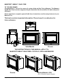
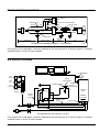
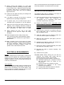
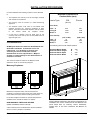
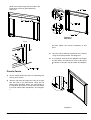
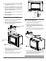
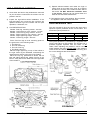
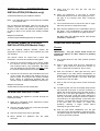
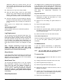
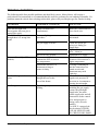
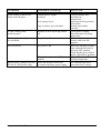
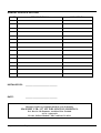
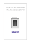
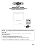
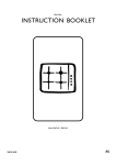
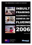
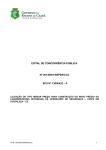
Masport Inbuilt Gas Fireplace
-1-
MASPORT INBUILT GAS FIRE
TO THE NEW OWNER
Congratulations! You are the owner of a state-of-the-art Gas Fire by Masport. The Masport
Inbuilt Gas Fires have been approved by the Australian Gas Association for both safety and
efficiency.
Please take time to acquaint yourself with these instructions and the many features of your
Masport Fire.
This book contains important information. Please keep it in a safe place for
future reference.
590
477
433
672
GAS INLET
CONNECTION
PICCOLO
79
63
563
560
116
363
GAS INLET
CONNECTION
EIS
64
964
149
Sofia/Madrid
Piccolo
THE INSTRUCTIONS IN THIS MANUAL APPLY TO;
MASPORT INBUILT GAS FIRES– PICCOLO, SOFIA AND MADRID
Piccolo
Sofia & Madrid - EIS
EIS => Electronic Ignition System.
Masport Inbuilt Gas Fireplace
-2-
TABLE OF CONTENTS
Contents
Page
Contents
Page
Installation Requirements
Wiring Diagrams ........................................4
Safety .... ...................................................5
Gas Pipe Testing .......................................5
Important requirements ..............................5
Specifications.............................................5
Log & Ember Placement...........................12
Gas Pressure Test ...................................12
Optional Wall Thermostat ........................13
Optional Remote Control..........................13
Operating Instructions
Installation Instructions
Electrical Requirements ............................6
Installation Sequence ................................6
Installation Procedure ................................7
Clearances to Combustibles ......................7
Flue System ...............................................8
Fire Installation ..........................................8
Combustion & Ventilation Air .....................8
Gas Connection .........................................8
Fascia Installation – Sofia & Madrid ..........9
- Piccolo.....................10
Glass Removal – Flush Front ..................11
- Bay Front..................11
Masport Inbuilt Gas Fireplace
Operating Instructions ..............................13
Lighting Procedure ...................................13
Shutdown Procedure................................14
The First Few Fires ..................................14
Fan Operation ..........................................14
Normal Operating Sounds of
Gas Appliances...................................15
Maintenance
General Maintenance...............................15
Servicing .................................................15
Log Replacement .....................................16
Glass Gasket............................................16
Gold Plated Trim ......................................16
Glass Replacement ..................................16
Fan Maintenance .....................................16
NG to LPG Conversion ............................17
Cleaning Instructions ...............................17
Troubleshooting .......................................18
-3-
PICCOLO WIRING DIAGRAM
SWITCH
CONNECTORS
BROWN
BLUE
YEL/GN
SIX PIN PLUG AND SOCKET
ORANGE
BRN
BLUE
RED
YEL/GN
CONNECTORS
ORANGE
RED
BLUE
WHITE
BROWN
WHITE
BLUE
BLACK
GREEN
FAN
EARTH POST
SWITCH LOOM
590226
MAINS LEAD
588068
FAN
ADAPTOR
LOOM
590227
FAN
586174
PICCOLO FAN WIRING DIAGRAM — TWO SPEED
590456
If the supply cord is damaged, it must be replaced by the manufacturer or its service agent or a similarly
qualified person in order to avoid a hazard.
EIS WIRING DIAGRAM
FAN
THERMODISC
Blue
FIRE
OFF/ON
Blk
EARTH
ELECTRODE
Blk
FIRE
LO/HI
Yel
6 PIN PLUG
FLAME SENSOR
Vi
SPARK
ELECTRODE
FAN
LO/OFF/HI
Red
CONTROL
PANEL
CONTROL
BOX
VALVE
FASCIA
EARTH
WIRE
THERMOSTAT LINK
MODULATOR
LEAD
9 PIN PLUG
VALVE LEAD
MAINS IN
EIS SCHEMATIC ELECTRICAL LAYOUT
If the supply cord is damaged, it must be replaced by the manufacturer or its service agent or a similarly
qualified person in order to avoid a hazard.
Masport Inbuilt Gas Fireplace
-4-
IMPORTANT:
SAVE THESE INSTRUCTIONS
The Masport Gas Fire must be installed in accordance
with these instructions. Carefully read all the
instructions in this manual first. Consult the "authority
having jurisdiction" to determine the need for a permit
prior to starting the installation.
Note:
Failure to follow these instructions could
cause a malfunction of the heater, which
could result in death, serious bodily injury,
and/or property damage. Failure to follow
these instructions may also void your fire
insurance and/or warranty.
protection of young children or the infirm, a secondary
guard is required.
Do not place articles on or against this appliance.
Do not use or store flammable materials near this
appliance.
Do not spray aerosols in the vicinity of this appliance
while it is in operation.
GAS PIPE TESTING
The appliance must be isolated from the gas supply
piping system by closing its individual manual shutoff
valve (not supplied with heater) during any pressure
testing of the gas supply piping system at test
pressures equal to or greater than 6 kPa.
WARNING.
Installation
Installation must be carried out by a registered installer
who, on completion of the installation, must issue a
certificate of compliance, in accordance with national
and/or local codes. If a certificate of compliance is not
issued then the Masport warranty may be void.
Warranty Repair & Annual Servicing
Warranty repair work must be carried out by a
recognised Masport gas fire Technician. It is
recommended that recognised Masport gas fire
Technicians are also used to carry out annual servicing
requirements (particularly during the warranty period).
For contact details of authorised Masport Technicians
in your locality, please contact the retailer from whom
the appliance was purchased.
The heater must be installed according to these
instructions and in compliance with all relevant
building, gas-fitting, electrical and other Statutory
Regulations (eg. AS 5601 (AG-601), NZS 5261). Any
shortcomings in the appliance and flue installation will
be the responsibility of the installer, and Masport Ltd
will not be accountable for any such failings or their
consequences.
This appliance must not be installed in a mobile home.
The appliance must be checked and serviced yearly by
an Authorised Technician.
FOR YOUR SAFETY
This appliance requires air for proper combustion.
Always provide adequate combustion and ventilation
air.
The guard is fitted to this appliance (Australia only) to
reduce the risk of fire or injury from burns and no part
of it should be permanently removed. For the
Masport Inbuilt Gas Fireplace
SPECIFICATIONS
Gas Consumption:
Fuel:
Electrical:
Fan:
Logs:
35MJ/h
Natural Gas or LPG
230-250 volts AC system
2 speed
Ceramic fibre, 6 per set
Before installation commences, check the data plate
on the appliance to verify that it is the correct type to
suit your gas and also that the gas consumption rate is
correct for your application.
IMPORTANT REQUIREMENTS
Installation must be carried out by a registered installer
who, on completion of the installation, must issue a
certificate of compliance, in accordance with national
and/or local codes. If a certificate of compliance is not
issued then the Masport warranty may be void.
1) The appliance installation must conform with local
codes or in the absence of local codes, to AG601,
NZS5261.
2) The appliance must be inspected before use and
at least annually by an authorised Technician.
More frequent cleaning may be required due to
excessive lint from carpeting, bedding material,
etc. It is imperative that control compartments,
burners and circulating air passageways of the
appliance are kept clean and free from excessive
lint.
3) See
general
construction
and
assembly
instructions. This appliance may only be installed
in a vented, non-combustible fireplace. The
appliance flue should be enclosed when installed
or passing through a living area, where children
may come in contact with it.
-5-
4) Always connect this fireplace to a flue pipe
terminating outside the building envelope. Never
vent to another room. Make sure that the flue pipe
is properly sized and is of adequate height to
provide the proper draft. Use only the Masport
approved flue kit.
5) Inspect the flue system annually for blockage and
any signs of deterioration.
6) If the glass is removed for servicing it must be
replaced prior to operating the appliance.
7) To prevent injury, do not allow anyone who is
unfamiliar with its operation to use the fireplace.
8)
Always turn off the gas valve before cleaning. For
relighting, refer to lighting instructions. Keep the
burner and control compartment clean by brushing
and vacuuming at least once a year.
9)
When cleaning the logs, use a soft clean
paintbrush as the logs are fragile and easily
damaged.
10) Clean the appliance with a damp cloth (never
when unit is hot). Never use an abrasive cleaner.
The glass should be cleaned with a gas fireplace
glass cleaner.
11) Make a periodic check of the burner for proper
position and condition. Visually check the flame of
the burner periodically, making sure the flames
are steady, not lifting or floating. If there is a
problem call an authorised Technician.
When connected with 240 volts, all appliances must be
electrically earthed in accordance with local codes.
INSTALLATION SEQUENCE
The Masport Gas Insert is installed in the steps as
listed below. Detailed instructions follow.
1) Check the clearances to ensure that the fire will fit
the fireplace recess and clearances to
combustibles will be maintained. (Also check
ventilation requirements.) See page 7.
2) Prepare the fireplace recess. The base of the
fireplace must be levelled by for example grouting
to prevent vibration from possible fan imbalance.
The base of the gasfire must be sitting on this flat
surface. See page 7.
3) Install the flue or flexi-liner in accordance with AG
601 or NZS 5261, refer to instructions provided
with the Masport flue kit.
4) Install the gasfire into the fireplace recess and
connect to the flue system. See page 8.
5) Make the gas connection (see page 8) and the
electrical connection.
6) Assemble and install the fascia and switches (on
the EIS models). See pages 9 & 10.
7) Remove the glass or window assembly and install
the embers etc. See page 11 &12.
8) Re-install the glass or window assembly. See
pages 11 & 12.
ELECTRICAL REQUIREMENTS
Piccolo
No mains voltage electric power supply is required for
the gas control to operate, but a 240-Volt AC supply is
required for the fan. Plug the 3-pin plug and lead into a
suitable receptacle. Do not cut the earth terminal off
under any circumstances.
Sofia & Madrid
Mains voltage electric power supply is required for the
gas control to operate on these models. A 240-Volt AC
power cord is connected to the control system. Plug
the 3-pin plug into a suitable receptacle. Do not cut the
earth terminal off under any circumstances.
Masport Inbuilt Gas Fireplace
9) Install louvres or grilles.
10) Final check: Before leaving this unit with the
customer, the installer must ensure that the
appliance is firing correctly. This includes:
a) Checking the injector pressure. See page 12.
b) Adjusting the primary air, if required, to ensure
that the flame does not carbon on the
components.
c) Ensuring that the flue is drawing correctly.
d) Instructing the customer in the correct
operation of the appliance.
e) Leaving these instructions with the customer.
f) Issuing a certificate of compliance.
-6-
INSTALLATION PROCEDURE
For safe installation the following matters must be attended
to;
•
The fireplace and chimney must be thoroughly cleaned
and checked for soundness.
•
The chimney must not connect to a solid fuel-burning
appliance.
•
The fireplace recess must have a non-metallic heat
resistant surround (eg. masonry) extending at least
520mm each side of the recess centerline and up at least
to
the mantel
above the fireplace
recess.
•
Minimum Clearances to
Combustibles (mm)
Fascia Type;
EIS
Piccolo
(Shown)
(From Unit)
A flue pipe or flexiliner must be fitted right up the
chimney and exit at the top and be terminated with an
approved gas cowl.
CLEARANCES
All Masport heaters are tested to New Zealand and
Australian standards. Clearances are for fire
hazard only. For durability of finishes and
surfaces you should contact the relevant
manufacturer for their specification. Masport
accepts no responsibility for the deterioration of
surfaces or finishes.
Sides A
Ceiling B
Mantel C
225
1400
1000
225
1400
1000
(From Fascia)
Sides D
Ceiling E
Mantel F
(672 x 964)
37
1288
328
(685 x 842)
99
1275
315
The following are for both Fascia options;
Maximum Mantel Depth
Minimum Hearth Height
Minimum Hearth Depth
Minimum Hearth Width
G
H
I
J
305
0
300
965
The minimum fireplace recess for the Masport Inbuilt
Gasfires is shown in the following diagram:
Masonry fireplaces
Measure the fireplace recess and remove bricks as
necessary to accept the firebox outer case. Clear away any
loose rubble and inspect before installing the fireplace.
For shallow fireplace recesses an optional deep fascia is
available which reduces the 490mm to 390mm.
NON MASONRY FIREPLACE RECESS
(ZERO CLEARANCE INSTALLATION)
A Zero Clearance Kit is available which allows installation
when no masonry fireplace is available.
Masport Inbuilt Gas Fireplace
NOTE: Mantel clearances and hearth requirements for
Installation into a Zero Clearance Kit are different from
those listed here for masonry recess installation.
Please refer to the Zero Clearance Kit Manual for
details.
-7-
FLUE SYSTEM
THE APPLIANCE MUST NOT BE CONNECTED TO A
CHIMNEY SERVING A SEPARATE SOLID FUEL
BURNING APPLIANCE.
This appliance is designed to attach to a 100mm
diameter type B-Vent or approved flexi-liner or listed
gas fuel type flue liner running the full length of the
chimney. A minimum flue height of 3.6m is
recommended and it maybe necessary to extend
beyond this. B-Vent flue must be supported by a flue
support - supplied by flue manufacturer. The Masport
Insert incorporates its own internal draft hood, so no
additional external draft hood is required.
Periodically check that the flue is unrestricted and an
adequate draft is present when the unit is in operation.
Install to AG 601, NZS 5261 or local codes.
Fire Installation
1) Remove the top and bottom louvres or grilles.
These lift up and then out. The bottom one has a
centre retaining screw, which must be turned 90°
anticlockwise first. (When refitting, simply press
the screw in to secure the louvre or grille).
2) Slide the fireplace into the recess and adjust the
case position so that it is level and its front top
flange is in line with the face of the fireplace
surround. Where seismic restraint is necessary,
screw the bottom of the case to the base of the
fireplace recess. The base of the fireplace must be
levelled by for example grouting to prevent
vibration from possible fan imbalance.
3) If space above the case for positioning and fixing
the flue is limited, greater access can be provided
by first removing the top louvre or grille by lifting it
upwards and outwards.
4) Then remove the 2 screws holding the top sliding
panel, one is located at each side of the fire. The
top front section of the case can now slide out as
illustrated to increase access.
5) Attach the flue to the flue spigot. The flue spigot of
the appliance will fit inside a standard flue and may
be fastened directly to the flue by sheet metal
screw or a B-Vent, single wall flue connector (not
available from Masport).
Combustion and Ventilation Air
WARNING: This appliance needs fresh air for safe
operation and must be installed with provisions for
adequate combustion and ventilation air available
to the room in which it is to be operating.
Air for combustion is drawn in through the front of the
unit; therefore, this area must be kept clear of any
obstructions.
GAS CONNECTION
GAS CONNECTION WARNING:
Installation must be carried out by a registered installer
who, on completion of the installation, must issue a
certificate of compliance, in accordance with national
and/or local codes. If a certificate of compliance is not
issued then the Masport warranty may be void..
The gas connections are a 3/8” flare for New Zealand
& 1/2" flare for Australia.
When connecting the gas, ensure that the control
valve or pressure regulator is not twisted during this
procedure (such damage is not covered by Masport
warranty).
6) Once the flue is connected, reassemble the fire.
Note:
Final gas connection should be after unit is
in place to avoid damage to line when
pushing the unit into position.
Masport Inbuilt Gas Fireplace
-8-
FASCIA INSTALLATION
BLUE
FIRE:
BLACK
OFF
ON
Sofia & Madrid EIS Models
1) Lay the fascia panels face down on something soft
to prevent them from being marked.
2) Align the bottom flange of each side panel with the
corresponding end of the bottom rail. Using the
self-tapping screws provided, attach the bottom rail
to the bottom flanges of the side panels. Tighten
the screws only loosely at this stage. See Fig 1.
FIRE:
BLACK
HIGH
LOW
YELLOW
FAN:
VIOLET
HIGH
OFF
LOW
BLACK
RED
Fig 2.
7) Ensure that the wires are away from the side of the
fireplace. The power cord should be run behind the
fascia panel and out through the slot in the side of
the fascia. The rubber grommet on the power cord
should be inserted into the slot to protect the mains
lead against possible damage.
Fig 1.
3) There are three switches supplied with the fascia.
If they have not already been assembled, insert
them in the rectangular holes in the left side of the
left fascia panel. The FAN switch (three terminals)
goes in the bottom hole either way up, the burner
HI/LO switch (two terminals with no printing on the
rocker) goes in the centre hole with the two
terminals at the bottom, while the ON/OFF switch
(two terminals) fits in the top hole with the
terminals at the top. (See Fig. 2).
8) Offer the fascia assembly up to the case to obtain
the correct width for the side panel spacing
keeping the inside flanges of each panel on the
inner side of the mounting flange of the fireplace.
Carefully remove the assembly and tighten the
screws fastening the bottom rail to the side panels.
9) Offer the fascia assembly up to the case once
more and connect the green earth wire to the tab
on the control valve then secure the fascia through
the two holes on the inner edges of each fascia
side panel using the self tapping screws provided.
See Fig 3.
4) Connect the fan wires, red, violet and black, to the
bottom fan switch, in the following positions. (See
Fig. 2).
- Black wire
to
centre terminal,
- Red wire
to
bottom terminal,
- Violet wire
to
top terminal.
5) Connect the burner HI/LO wires, yellow and black,
to the centre switch in the following positions. (See
Fig. 2).
- Black wire
to
top/centre terminal,
- Yellow wire to
bottom terminal.
6) Connect the burner ON/OFF wires, blue and black,
to the top switch in the following positions. (See
Fig. 2).
- Blue wire
to
upper terminal,
- Black wire
to
lower terminal.
Masport Inbuilt Gas Fireplace
Fig 3.
10) Lower the top panel assembly into place with the
locating prongs pointing down so that they fit inside
the top edges of each side panel. Fasten the top
-9-
panel to the case through the two holes in the
lower flange of the top panel assembly.
See Fig 4.
Diagram 1
Rear View
Fig 4.
Do NOT tighten the screws completely at this
point.
3)
Next the Fascia stiffener is attached to the Fascia
using the screws provided. See Diagram 1.
4) If not already fitted push the Masport logo badge
into the holes in the bottom left corner of the fascia
and attach it using the clips provided. See diagram
2.
Piccolo Fascia
1) Lay the fascia panels face down on something soft
so they don't scratch.
2) Take the top panel and align the holes at its ends
with the holes in the side panels. Using the flat
head screws provided, attach the side panels to
the top panel (the holes in the top panel are slotted
to provide fascia width adjustment). See Diagram
1.
Diagram 2
Masport Inbuilt Gas Fireplace
- 10 -
5) Offer the fascia into position on the unit and adjust
until it fits correctly. Remove the fascia carefully
and tighten all the screws
6) The power cord should be run behind the fascia
panel and out through the slot in the bottom of the
fascia. The rubber grommet on the power cord
should be inserted into the slot to protect the mains
lead against possible damage.
Note: There is no fan switch on the Piccolo as it
is a single speed fan.
INSERT SCREWDRIVER
TO LIFT TRIM.
7) Attach the assembled fascia to the case using the
4 remaining screws.
Diagram 2
FLUSH FRONT GLASS REMOVAL
1)
Remove the top louvre by lifting it upwards and
outwards to clear the retaining pins.
BAY FRONT REMOVAL
2)
Remove the two trim fastening screws, one at
each end of the top trim as per the diagram below
and remove the top glass trim.
1)
Remove the top grille by lifting it upwards and
outwards to clear the retaining pins.
2)
Release the bottom grille retaining screw one
quarter turn anticlockwise and remove the bottom
grille by lifting it upwards and outwards to clear
the retaining pins.
TRIM FASTENING
SCREW.
3) Remove the two window fastening screws, one at
either end of the window as per the diagram below.
TOP GLASS
TRIM
SIDE GLASS
TRIM
3)
4)
Remove the 2 black cover trims one at each side
of the glass by lifting them upwards and then out.
Refer to diagram 2. Pull the top of the trim
forward before the bottom.
This will now free the glass for removal from the
fire and give access to the logs, burner etc.
Masport Inbuilt Gas Fireplace
4) This will now free the window for removal from the
fire by swinging the top outwards slightly and lifting
the bottom edge clear of its retaining channel. This
will give access to the logs, burner etc.
- 11 -
LOG & EMBER PLACEMENT
1) Once either the flush or bay windows are removed
as per the above instructions the embers can be
placed in the fire.
2) Inspect the logs before ember installation. If the
logs are broken, do not use the fire until they are
replaced. Broken logs can interfere with the pilot
operation, combustion, etc.
3) LOG IDENTIFICATION
790338 - Rear log, mounting centres - 340 mm
990339 - Left Centre log, mtg. centres - 115 mm
790356 - Left Front log, mtg. centres - 93 mm
790341 - Right Lower log, mtg. centres - 122 mm
790342 - Right Upper log, length - 245 mm
790343 - Centre log, length - 255 mm
Fit the first four logs on their mounting posts on
the gas burner in the following order:1. The Rear log
2. The Left Centre log
3. The Left Front log
4. The Right Lower log
Place the right Upper log on top of the hollow in
the right Lower log as illustrated, maintaining the
130 dimension shown to the rear of the firebox.
Place the Top log, positioned as shown with its
butt end sitting against the raised front lip of the
burner. Verify the correct distances to the right side
of the firebox.5.
4) Spread embers between and under the logs no
further than 50 mm back from front lip of burner
and also on the floor of the firebox at each side of
the burner. Do NOT block the ventilation slots
in the burner. Embers can be placed down the
sides to hide the black steelwork etc.
5) Re-install the flush or bay window. Do not operate
the appliance with the window removed.
GAS PRESSURE TEST
The unit is preset to give the correct gas input at the
specified injector pressures shown on the label. The
maximum injector pressure is:
Gas Type
Natural Gas
Propane
Piccolo
Low
High
0.30kPa
0.75kPa
0.90kPa
2.10kPa
EIS
Low
High
0.35kPa 0.82kPa
1.00kPa 2.30kPa
The injector pressure is controlled by a regulator built
into the gas valve on EIS models. The Piccolo has a
pressure regulator separate from the valve. In all
cases, when adjusting the pressure, check it at the
outlet pressure test point on the valve. The pressure
check should be carried out with the unit burning and
the correct pressures are shown above.
Piccolo
EIS Models
Masport Inbuilt Gas Fireplace
- 12 -
OPTIONAL WALL THERMOSTAT
INSTALLATION (EIS Models only)
A wall thermostat may be installed if desired.
Note: It is preferable that the thermostat be installed
on an interior wall.
Use an approved thermostat, rated for use with 24V
systems. Connect the thermostat to the terminals at
the front of the control box (behind the bottom louvre
or grille) in place of the jumper wire already installed
there.
Masport Part Number
791360 Programmable/Digital Wall Thermostat
OPTIONAL REMOTE CONTROL
INSTALLATION (EIS Models Only)
Use the Optional Masport Remote Control Kit
approved for this unit. Use of other systems may void
your warranty.
The remote control kit comes with a hand held
transmitter, a receiver and a wall mounting plate.
1) Choose a convenient location on the wall to install
the receiver and the receptacle box (protection
from extreme heat is very important). Run wires
from the appliance to that location. (Do NOT install
the receiver install behind the louvres or grille).
2) Connect the two wires to the terminals at the front
of the control box (behind the bottom louvre or
grille) in place of the jumper wire already installed
there. (Refer to instructions supplied with the
remote control for detailed installation instructions)
Masport Part Number
791397 Remote Control Thermostat (RF)
OPERATING INSTRUCTIONS
Before operating this appliance, proceed through the
following checklist.
1) Read and understand these instructions before
operating this appliance.
2) Check to see that all wiring is correct and enclosed
to prevent possible shock.
3) Check to ensure there are no gas leaks.
4) Never operate the appliance with the glass
removed.
Masport Inbuilt Gas Fireplace
5) Verify that the flue and the flue cap are
unobstructed.
6) Verify log placement. If the pilot or ignition
electrodes cannot be seen when lighting the unit the logs or the embers have been incorrectly
positioned.
7) The unit should never be turned off and on again
without a minimum of a 60-second wait.
8) Each time the appliance is lit, condensation will fog
the glass. This condensation is normal and will
disappear in a few minutes as the glass heats up.
DO NOT USE THE HEATER WITH THE GLASS
ASSEMBLY REMOVED.
LIGHTING PROCEDURE
Piccolo
IMPORTANT: The gas control knob cannot be
turned from "PILOT" to "OFF" unless it is partially
depressed.
1) If the control knob is in the "OFF" position proceed
to Step 4.
2) Push in gas control knob and turn clockwise to
"OFF". Knob cannot be turned from "PILOT" to
"OFF" unless knob is pushed in. Do not force.
3) Wait five minutes to allow gas that may have
accumulated in the main burner compartment, to
escape. If you do smell gas, follow the instructions
on the front of this manual. If you don't smell gas
continue on to the next step.
4) Push in and turn the gas control counter clockwise
to "IGN".
5) The piezo igniter will click as a spark jumps across
the terminals at the pilot. It may be necessary to
repeat this several times before the pilot ignites if
there is air in the pilot light pipeline. The pilot is
located at the right, inside the firebox behind the
front log. When the pilot lights continue to hold the
control knob in for approximately 15 seconds, then
release it. The pilot flame should continue to burn.
If the pilot does not remain lit, repeat this
operation, allowing a longer period before
releasing the gas control knob.
6) With the pilot flame established, turn the gas
control knob fully anticlockwise to ignite the burner.
The flame height can then be adjusted as required
by turning the knob clockwise.
- 13 -
EIS Models
Assuming that there is a gas supply to the valve and
that the mains power is switched ON, the operating
sequence is as follows:1) The on/off switch on the LH side of the fascia is
switched to the “ON” position. This is the top
switch.
2) If the thermostat loop is in place across the
thermostat terminals, a 24 V signal will go to the
relay, which closes and sends a mains signal to the
igniter module to initiate the ignition sequence.
3) About 3 seconds after the ignition module is
activated, there will be a continuous spark at the
ignition electrodes.
4) If there is no spark, the On/Off switch needs to be
cycled to reset the ignition module at which time it
will repeat the ignition cycle.
5) If the spark stops before the burner ignites, again
the On/Off switch needs to be cycled to reset the
ignition module at which time it will repeat the
ignition cycle. Sometimes, with a new installation, it
will take several attempts to give sufficient time to
bleed air out of the pipeline.
2) Use the bottom rocker switch, if desired to turn off
the fan immediately. If not manually switched off
the fan will automatically turn off once the
appliance has cooled to a point where no more
useful heat can be produced.
3) Disconnect all electric power and gas to the
appliance if service is to be performed.
THE FIRST FEW FIRES
The first few fires in your stove are part of the curing
process. When first operated, the unit will release an
odour and the flames will appear orange caused by the
curing of the paint, the burning off of the starch in the
gas logs and the oils on the metal.
After several fires the starch in the logs may show as a
deposit inside the glass. If this film is not removed it
will bake on and may become very difficult to remove.
When the glass is cold, remove it (see page 11) and
clean the inside with a non-abrasive cleaner.
DO NOT ATTEMPT TO CLEAN THE GLASS WHILE
IT IS HOT. NEVER OPERATE THE UNIT WITH THE
GLASS REMOVED.
6) As soon as the burner lights, the flame sensor will
signal the high-tension spark to stop.
FAN OPERATION
7) The flame height can be controlled with the middle
rocker switch on the LH side of the fascia. Note that
flame size only changes between high and low.
Note: It is possible to use the fire with the fan not going
although for better air circulation and heat discharge
area temperature reduction using the fan is
recommended.
8) While the fan speed can be pre-selected at this
time, using the lower rocker switch, the fan will not
start until the firebox has reached a reasonable
working temperature.
The fan will
start
automatically once this has been attained. (Usually
about 10 minutes, depending on the flame height).
SHUTDOWN PROCEDURE
Piccolo
1) Push the knob in momentarily and rotate clockwise
to the pilot position. To extinguish the pilot, push
the knob in and turn clockwise to the “OFF”
position. Do not force.
2) Disconnect all electric power and gas to the
appliance if service is to be performed.
EIS
1) Use the top rocker switch to turn off the main
burner.
Masport Inbuilt Gas Fireplace
Piccolo
The fan operates by using the rocker switch on the lefthand side of the fascia. To adjust the desired fan
speed, operate the rocker switch. The fan has 2
speeds, a high speed for more rapid air movement and
a low speed. The fan should not be used until the fire is
up to operating temperature, approximately 10mins.
The fan can be left running after the fire has been shut
down until it is circulating no more useful heat.
EIS Models
The fan operates by using the bottom of the 3 rocker
switches on the left-hand side of the fascia. To adjust
the desired fan speed, operate the rocker switch. The
fan has 2 speeds, a high speed for more rapid air
movement and a low speed.
NOTE: EIS models are fitted with a thermodisc fan
control. This means the fan will operate only when the
heater is up to operating temperature (approximately
10 minutes from start on high burn) and will stop
automatically once the heater has cooled down. This
is particularly useful when a thermostat is fitted, as the
fan will not be running unnecessarily. Because the
- 14 -
thermodisc is fitted, it is not necessary to operate the
switch on the fascia. It can be kept permanently on at
the desired speed setting. The fascia switch overrides
the thermodisc if it is set in the central “off” position.
NORMAL OPERATING SOUNDS OF
GAS APPLIANCES
It is possible that you will hear some sounds from your
gas appliance. This is perfectly normal due to the fact
that there are various gauges and types of steel used
within your appliance. Listed below are some
examples,
all are normal operating sounds and these should
not be considered as defects in your appliance.
Fan:
Masport gas appliances use high tech blowers to push
heated air further into the room. It is not unusual for
the fan to make a "whirring" sound when ON. This
sound will increase or decrease in volume depending
on the speed setting of your fan.
Burner Tray:
The burner tray is positioned directly under the burner
and logs and is made of a different gauge material
from the rest of the firebox and body. Therefore, the
varying thicknesses of steel will expand and contract at
slightly different rates, which can cause "ticking" and
"cracking" sounds. You should also be aware that as
there are temperature changes within the unit these
sounds would likely re-occur, again, this is normal for
steel fireboxes.
Pilot Flame (Piccolo Only):
While the pilot flame is on it can make a very slight
"whisper" sound.
2) Clean the appliance, glass and louvres with a
damp cloth only when it is cold. Never use an
abrasive cleaner. The gold louvres will be
scratched if abrasives are used to clean them.
The heater is finished in a heat resistant paint and
should only be refinished with heat resistant paint
(not with wall paint).
3) Keep the area near the appliance clear and free
from combustible materials, petrol and other
flammable vapours and liquids.
WARNING: CHILDREN AND ADULTS SHOULD
BE ALERTED TO THE HAZARDS OF HIGH
SURFACE TEMPERATURE AND SHOULD
STAY AWAY TO AVOID BURNS OR CLOTHING
IGNITION. YOUNG CHILDREN SHOULD BE
CAREFULLY SUPERVISED WHEN THEY ARE
IN THE SAME ROOM AS THE APPLIANCE.
CAUTION: ANY SAFETY SCREEN OR GUARD
REMOVED FOR SERVICING AN APPLIANCE
MUST BE REPLACED PRIOR TO OPERATING
THE APPLIANCE. (Australia only)
CLOTHING
OR
OTHER
FLAMMABLE
MATERIAL SHOULD NOT BE PLACED ON OR
NEAR THE APPLIANCE.
4) Periodically check the pilot flames (Piccolo only),
there should be three strong flames (approx. 19
mm long) - 1 flame to the rear burner, 1 to the
ignition electrode and 1 to the thermocouple.
If you have an incorrect flame pattern, contact your
Masport dealer.
SERVICING INSTRUCTIONS
Gas Control Valve:
As the gas control valve turns ON and OFF, a dull
clicking sound may be audible, this is normal operation
of a gas regulator or valve.
Unit Body/Firebox:
Different types and thicknesses of steel will expand
and contract at different rates resulting in some
"cracking" and "ticking" sounds being heard throughout
the cycling process.
GENERAL MAINTENANCE
INSTRUCTIONS
1) Keep the burner and control compartment clean by
brushing and vacuuming at least once a year.
Always turn the gas valve to OFF before cleaning.
When cleaning the logs, use a clean soft
paintbrush, as the logs are fragile and easily
damaged.
Masport Inbuilt Gas Fireplace
(Routine maintenance schedule)
Servicing must be carried out only by authorised
personnel.
Your Masport heater must be checked yearly by an
authorised Technician. This periodic maintenance
should cover the following points:1) Keep the burner and control compartment and any
air entry points clean by brushing and vacuuming.
Always turn the gas valve to OFF before cleaning.
When cleaning the logs, use a clean soft
paintbrush, as the logs are fragile and easily
damaged.
2) Make a periodic check of burner for proper log
position and condition. Visually check the flame
pattern of the burner periodically, making sure the
flames are steady, not lifting or floating.
3) The appliance and flue system must be inspected
before use and thereafter annually to ensure that
the flow of combustion and ventilation air is not
- 15 -
obstructed. During the annual service call, the
burner should be removed from the burner tray
and cleaned. Replace the embers but do not block
the air slots.
4) Clean the fan of any lint or foreign matter.
5) After the above steps, check the pilot flames
(Piccolo only), there should be three strong flames
approx. 19 mm long - 1 flame to the rear burner, 1
to the ignition electrode and 1 to the thermocouple.
6) Check the operation of the thermostat (if fitted) by
turning its control point above and below ambient
room temperature and checking the response of
the fire.
Other points to be checked after completing the
above:Thermocouple generation
Gas consumption rate
Carbon dioxide content in the combustion products
Flue operation.
Log Replacement
The unit should never be used with broken logs. Turn
off the gas valve and allow the unit to cool before
removing the glass to carefully remove the logs. The
pilot light generates enough heat to burn someone. If
for any reason a log should need replacement, you
must use the proper replacement log. The position of
these logs must be as shown in the diagram on page
12.
Note: Improper positioning of logs may create
carbon build-up and will alter the unit’s
performance. Malfunctioning due to improper log
placement is not covered under warranty.
Your Masport stove is supplied with high temperature,
5 mm Neoceram ceramic glass that will withstand the
highest heat that your unit will produce. In the event
that you break your glass by impact, purchase your
replacement from an authorised Masport dealer only,
and follow our step-by-step instructions for
replacement.
Bay Glass Removal
1) Remove the window from the unit (refer to removal
instructions on page 10) and place on a soft
surface to prevent scratching.
2) Remove the nuts holding the glass retainers in
place.
3) Remove the glass retainers.
4) Replace the glass.
5) Reverse the previous steps, replace the retainers
and fasten with the nuts but do not over tighten, as
this can break the glass.
6) Refit the window to the fire and check the seal.
Flush Glass Replacement
Remove the glass by following the instructions on page
11. Fit the new glass, replacing the gaskets if
necessary.
Fan Maintenance
If your fan requires maintenance or replacement,
access to the fan is through the plate on the rear wall
of the firebox.
Note:
Glass Gasket
The unit MUST NOT be operated without
the fan access panel securely in place.
If the glass gasket requires replacement use 25mm flat
glass gasket for the Flush Front, Masport part number
786774 or 10mm flat glass tape for the curved window
Masport part number 790229.
To remove fan:
Gold-Plated Trim
2) Unplug or disconnect the power source to the fire.
The 24-carat gold plated finish on the trim requires
little maintenance, needing only be cleaned with a
damp cloth. DO NOT use abrasive materials or
chemical cleaners, as they will harm the finish and
void the warranty. Clean any fingerprints off before
turning the unit on. If the top louvres start to
discolour, check the glass gasket seal and replace
if necessary.
3) Remove glass front (see page 11).
Glass Replacement
1) Turn the unit and/or pilot off and allow it to cool to
room temperature.
4) Remove logs and embers (see page 12).
5) Remove the burner (2 screws at the front, refer to
diagram over page).
6) Loosen the screws securing the rear fan access
panel in place. Lift and withdraw the panel passing
the keyhole slots over the screw heads.
7) Remove the fan-shipping nuts.
Masport Inbuilt Gas Fireplace
- 16 -
8) Unplug the fan lead from the plug on the control
box (EIS models). On Piccolo models the mains
lead will need withdrawing with the fan or unplug
the individual wires.
9) On EIS models remove the screws holding the
thermodisc bracket or disconnect the two push on
connectors at the thermodisc.
10) On Piccolo models, disconnect the wires at the
earthing post on the rear wall just above the fan
motor.
11) Lift and withdraw the fan assembly from its
mounting pins on the base of the fire. The fan will
come out through the access panel.
BURNER
FASTENING SCREW
12) Reassemble in the reverse order.
NG to LP Conversion (EIS Models):
This conversion must be carried out by a qualified
Technician. If in doubt do not attempt this
conversion!
DETAIL
B
1) Turn the unit off.
2) Unplug or disconnect the power source to the fire.
3) Remove the glass front (see page 11).
CLEANING INSTRUCTIONS
4) Remove the logs (see page 12).
5) Remove the 2 screws holding the burner assembly
to the burner tray as below. Push the burner to the
left and lift out.
6) Access is now available to the brass main injector.
A 13mm spanner will be required to remove the
injector, the elbow behind the injector will also
need to be held to avoid twisting the pipe work.
Remove the main injector and discard.
7) Reinstall the new LP injector marked “1.7” and
tighten. Again avoid twisting the pipe work.
8) Reinstall the burner. Ensure that the aeration
shutter on the burner is fully open.
The outside of the fascia and glass should need no
more than an occasional wipe with a damp cloth to
remove any dust which may have settled.
All gas appliances incorporating a live fuel effect and
designed to operate with luminous flames may exhibit
carbon deposition, particularly if the combustion air
entry slots under the heater are obstructed or the
aeration air inlets are clogged with lint. Any other
lifting, floating or lighting back should be checked by a
recognised Masport gas fire Technician.
After a period of time the inside of the glass may
require cleaning. To do this, carefully remove the glass
(See Glass Removal and Assembly, page 11), and
clean the inside surface with a non-abrasive cloth and
a non-scratching type household cleaning liquid.
9) Reverse steps 4), 3) & 2).
10) Check for gas leaks.
11) Reset high and low pressures refer to page 12.
Replace the parts as detailed on page 11, keeping
fingerprints off the inside glass surfaces.
No other user maintenance should be necessary. If you
require any other service or adjustments, contact your
Technician or Dealer.
12) Check operation at high and low settings.
Masport Inbuilt Gas Fireplace
- 17 -
TROUBLE - SHOOTING
The following table lists possible problems and their likely causes. Most of these will require a
professional serviceman and we recommend that this work be performed by an Authorised Installer. If a
problem cannot be solved after referring to this table, please call your Masport gas fire Dealer for help.
PROBLEM
POSSIBLE CAUSE(S)
SOLUTION
Pilot will not light, and
Piezo igniter does not give a
strong blue spark.
Pilot will not light even
though there is a strong blue
spark.
Faulty electrode wire
connection(s).
Make sure connections are
firm, check wire.
Incorrect lighting
procedure.
Follow the instructions in
this manual.
No gas supply at heater.
Check for closed gas
valve(s) or faulty gas
supply lines.
Replace filter in control
valve - clean jet.
Replenish LPG supply.
Check thermostat setting.
Switch to ON or turn to a
higher temperature.
If wiring is undamaged
and the connections are
sound at each end,
thermostat may need
replacing.
Check for flue blockage,
negative air pressure in
the room or circumstances
causing down draught.
Check all joints for leaks,
including the gas supply
system, the pilot light
supply tube, the main
burner supply tube and all
connections to the control
valve and pressure reducing valve (Piccolo
models).
Use ONLY a proper leak
check solution. NEVER
USE AN OPEN FLAME
TO CHECK FOR LEAKS
Pilot filter or jet blocked.
Burner will not light (EIS
models).
No fuel in LPG system.
Thermostat (if fitted) is
switched to OFF or set to a
low temperature.
Thermostat defective, or
thermostat wiring to
heater is faulty.
Smell of flue gas in the
room.
Flue gas spilling from the
draught diverter at the
rear of the heater.
Smell of gas in the room.
Pipe fittings may be
leaking.
Masport Inbuilt Gas Fireplace
- 18 -
PROBLEM
POSSIBLE CAUSE(S)
SOLUTION
A thin coating of black soot
forms inside the glass.
Combustion air supply
restricted.
Clean all primary and
secondary air
passageways.
Adjust gas delivery pressure
at test point.
Arrange logs/embers
correctly.
Follow glass cleaning
directions under Cleaning
Instructions.
Disconnect electrical power.
Remove and clean fan
impeller.
Make sure fan plug is firmly
home and that fan switch is
not in the OFF position.
Check that the power socket
works with another appliance.
Wait until heater achieves
working temperature.
Get a qualified person to
correct the house wiring.
Over-supply of gas.
Logs or embers out of position.
A white coating forms
inside the glass.
Residues in new logs being burned
off.
Fan hums but there is poor
air circulation.
Dirty fan impeller
Fan will not run.
No power to fan.
Ignition spark continues after the
fire has lit. (EIS models only)
Thermodisc not activated (EIS
models)
Phase and Neutral connections
reversed in the house power supply.
Masport Inbuilt Gas Fireplace
- 19 -
ANNUAL SERVICE RECORD
DATE
SERVICE DETAILS
INSTALLED BY:
____________________________
DATE:
____________________________
SERVICED BY
Masport Gasfires are manufactured in New Zealand by
MASPORT LTD. 1/37 MT WELLINGTON HIGHWAY.
P.O. Box 14-349 Panmure, Auckland New Zealand.
A.G.A. Approvals:
Piccolo, Sofia & Madrid - All Certificate No 6361.
Masport Inbuilt Gas Fireplace
- 20 -