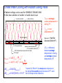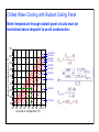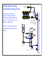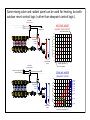
1
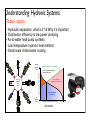
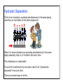
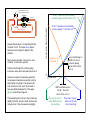
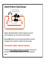
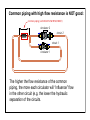
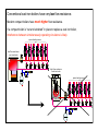
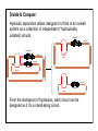
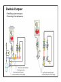
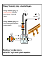
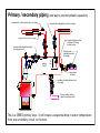
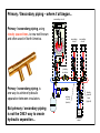
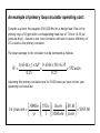
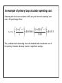
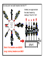
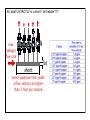
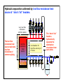
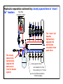
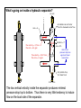
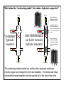
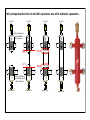
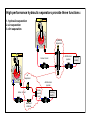
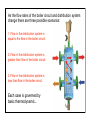
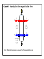
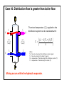
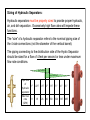
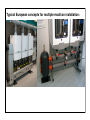
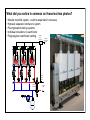
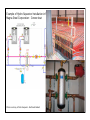
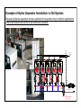
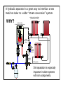
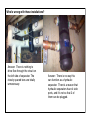
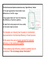
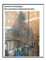
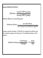
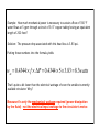
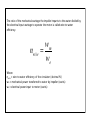
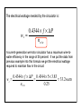
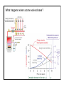
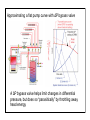
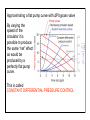
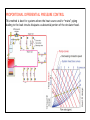
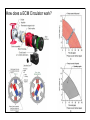
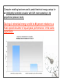
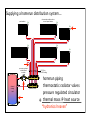
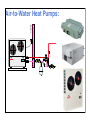
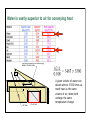
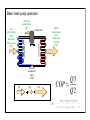
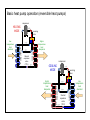
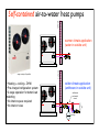
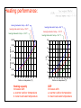
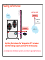
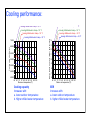
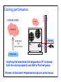
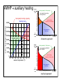
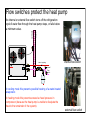
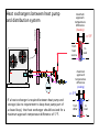
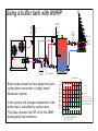
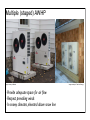
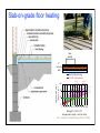
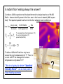
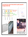
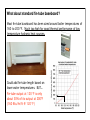
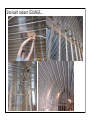
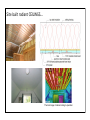
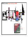
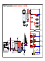
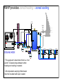
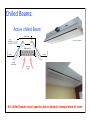
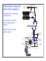
Understanding Hydronic Systems
Mestek Institute,
June 16, 2014
Presented by: John Siegenthaler, P.E.
© Copyright 2014, J. Siegenthaler, all rights reserved.
The contents of this file shall not be copied or
transmitted in any form without written permission of
the author. All diagrams shown in this file on conceptual
and not intended as fully detailed installation drawings.
No warranty is made as the the suitability of any
drawings or data for a particular application.
Understanding Hydronic Systems
Today’s topics...
• Hydraulic separation, what is it? & Why itʼs important
• Distribution efficiency & low power pumping
• Air-to-water heat pump systems
• Low temperature hydronic heat emitters
• Small scale chilled water cooling
very low
head loss!
inside
header
space heating load (Btu/hr)
design!
heating!
load
no!
heating!
load
heating capacity of heat pump
heat supplied by auxiliary!
heating element
spare heating!
capacity of heat pump
heat supplied by
heat pump
during of heating season (hours)
All electric
5000 hours
Hydraulic Separation
What it is.
Why itʼs important.
How to achieve it.
Hydraulic Separation:
Think of two circulators, operating simultaneously in the same piping
assembly, as rival bullies on the same playground.
When 2 or more circulators are operating simultaneously in the same
piping assembly, they try to “interfere” with each other.
This interference is undesirable!
To avoid this interference the circulators need to be “hydraulically
separated” from each other.
There are several ways to do this...
What is “COMMON PIPING?”
Itʼs the piping components shared by two or more circuits.
common piping
circulator 2
circuit 2
circuit 1
circulator 1
The degree to which two or more operating circulators interact with
each other depends on the head loss of the common piping.
The lower the head loss of the common piping the less
the circulators will interfere with each other.
When the head loss of the common piping is very low,
there is “hydraulic separation” between the circuits.
When the head loss of the common piping is very low,
there is “hydraulic separation” between the circuits.
Very little head loss occurs!
in this portion of the circuits.
circulator 2
circuit 2
circuit 1
circulator 1
common piping
Very little head loss occurs!
in this portion of the circuits.
circuit 1 head loss curve including !
common piping (both circulators on)
circulator 2
circuit 2
circuit 1
common piping
Assume that circulator 1 is operating, but that
circulator 2 is off. The lower (blue) system
head loss curve in figure 2 applies to this
situation.
head loss (feet of head)
circulator 1
Next, assume circulator 2 is turned on, and
circulator 1 continues to operate.
circuit 1 head loss curve including !
common piping (1 circulator on)
pump curve!
(circulator 1)
The flow rate through the common piping
increases, and so does the head loss across it.
However, because of its spacious geometry,
the increase in head loss across the common
piping will be very slight. The system head
loss curve that is now “seen” by circulator 1
has very slightly steepened. It is the upper,
(green) curve shown in figure 2.
The operating point of circuit 1 has moved very
slightly to the left, and as a result, the flow rate
through circuit 1 has decreased very slightly.
0
very small change in!
head loss across!
common piping!
when both circuits
are on
0 flow rate
VERY small decrease in!
circuit 1 flow rate!
when circuit 2 is on
flow rate in circuit 1
when BOTH circuits!
are operating
flow rate in circuit 1
when it is the only
circuit operating
Almost Perfect Is Good Enough:
Very little head loss occurs!
in this portion of the circuits.
circulator 2
circuit 2
circuit 1
circulator 1
common piping
Imagine a hypothetical situation in which the head loss across the
common piping was zero, even with both circuits operating.
Because NO head loss occurs across the common piping, it would be
impossible for either circulator to “influence” the other circulator.
This would be “perfect” hydraulic separation.
Fortunately, perfect hydraulic separation is not required to ensure that the
flow rates through independently operated circuits remain reasonably
stable.
Common piping with high flow resistance is NOT good:
common piping (with HIGH FLOW RESISTANCE)
circulator 2
circuit 2
circuit 1
circulator 1
The higher the flow resistance of the common
piping, the more each circulator will “influence” flow
in the other circuit (e.g. the lower the hydraulic
separation of the circuits.
2
0
4 psi ∆P at 0 flow
small circulator
10
5
P=17psi
P=22 psi
pump curve!
for small circulator
0
0
2
4
6
8
flow rate (gpm)
10
large circulator
ON
∆P= 10 psi
ON
P=12 psi
smaller
circulator
∆P= 5 psi
common piping and !
heat source have!
HIGH FLOW RESISTANCE
P=16 psi
larger
circulator
ON
P=13 psi
ON
backseated!
flow check
∆P = 5 psi
4
15
∆P produced"
by circulator"
@ 0 flow = 4 psi
6
head added (feet)
" D %
!P = ( Head ) $
'
# 144 &
High flow resistance common piping - something to avoid
P=17 psi
no flow
common piping and !
heat source have!
high flow resistance
Conventional cast-iron boilers have very low flow resistance.
Modern compact boilers have much higher flow resistance.
If a compact boiler is “cut and soldered” in place to replace a cast iron boiler,
Interference between simultaneously operating circulators is likely.
space heating zones
low flow resistance
cast-iron boiler
high flow resistance
mod/con boiler
space heating zones
Divide & Conquer:
Hydraulic separation allows designers to think of an overall
system as a collection of independent (“hydraulically
isolated) circuits.
circulator 2
circuit 2
circulator 2
circuit 2
common!
piping
circuit 1
common!
piping
circulator 1
circuit 1
common!
piping
circulator 1
From the standpoint of hydraulics, each circuit can be
designed as if itʼs a stand-along circuit.
Divide & Conquer:
• Simplifying system analysis
• Preventing flow interference
Primary / Secondary piping - where it all began...
flow-check
valve
Primary / secondary piping, using
closely spaced tees, is now well
known and often used in North
America.
secondary circuit
Primary / secondary piping, is one
way to achieve hydraulic separation
between circulators
secondary
circulator
primary
circulator
closely
spaced
tees
primary loop
flow
D
maximum 4xD
But primary / secondary piping is
not the ONLY way to create hydraulic separation...
Primary / secondary piping (one way to provide hydraulic separation)
swing check (or flow-check) valve (on return)
circulator with integral flow-check (on supply)
spring-load check valve on supply
underslung thermal trap!
(minimum 18" deep)!
protects return
circulator with integral flow-check !
(on primary circuit)
circulator with !
integral flow-check !
(on supply)
primary!
circuit
18"!
min.
swing-check !
on return
circulator with integral flow-check !
(on supply)
this secondary circuit is
lower than primary circuit
This is a SERIES primary loop. It will create a sequential drop in water temperature
from one secondary circuit to the next.
Primary / Secondary piping - where it all began...
secondary circuit
Primary / secondary piping, using
closely spaced tees, is now well known
and often used in North America.
secondary!
circuit
secondary!
circuit
load!
#1
load!
#2
primary!
circulator
Primary / secondary piping, is
one way to achieve hydraulic
separation between circulators.
But primary / secondary piping
is not the ONLY way to create
hydraulic separation...
closely!
spaced!
tees!
(typical)
primary!
circuit!
(series)
load!
#3
secondary!
circuit
Series and parallel primary/secondary systems
secondary circuit
SERIES primary loop
secondary!
circuit
secondary!
circuit
load!
#1
load!
#2
PARALLEL primary loop
load!
#1
load!
#2
load!
#3
primary!
circulator
primary!
circulator
parallel!
primary!
circuit
closely!
spaced!
tees!
(typical)
primary!
circuit!
(series)
crossover!
bridge
closely!
spaced!
tees
balancing valves
load!
#3
secondary!
circuit
Both series and parallel primary/secondary systems require a primary circulator.
This adds to the installed cost of the system AND adds hundreds, even
thousands of dollars in operating cost over a typical system life.
An example of primary loop circulator operating cost:
Consider a system that supplies 500,000 Btu/hr at design load. Flow in the
primary loop is 50 gpm with a corresponding head loss of 15 feet (6.35 psi
pressure drop). Assume a wet rotor circulator with wire-to-water efficiency of
25 is used as the primary circulator.
The input wattage to the circulator can be estimated as follows:
0.4344 × f × ΔP 0.4344 × 50 × 6.35
W=
=
= 552watts
0.25
0.25
Assuming this primary circulator runs for 3000 hours per year its first year
operating cost would be:
⎛ 3000hr ⎞ ⎛ 552w ⎞ ⎛ 1kwhr ⎞ ⎛ $0.10 ⎞
1st year cost = ⎜
⎟⎜
⎟⎜
⎟ = $165.60
⎟⎜
⎝ yr ⎠ ⎝ 1 ⎠ ⎝ 1000whr ⎠ ⎝ kwhr ⎠
An example of primary loop circulator operating cost:
Assuming electrical cost escalates at 4% per year the total operating cost
over a 20-year design life is:
⎛ (1+ i ) N −1 ⎞
⎛ (1+ 0.04 )20 −1 ⎞
⎟ = $165.60 × ⎜
⎟ = $4, 931
cT = c1 × ⎜⎜
⎟
⎜
⎟
i
0.04
⎝
⎠
⎝
⎠
This, combined with eliminating the multi-hundred dollar installation cost of
the primary circulator obviously results in significant savings.
Question: What is the “ideal” header in a hydronic system?
Answer: One that splits up the flow without creating head loss
Think about a “copper basketball” with pipes sticking out of it
in all directions.
very low
head loss!
inside
header
Wouldnʼt this be pretty
close to an ideal header???
So why donʼt we build headers like this???
Instead, we approximate
the ideal header by
making it “short” & “fat”
very low
head loss!
inside
header
fat
Short / fat headers are GOOD!
Long / skinny headers are BAD!
short
So whatʼs EXACTLY is a short / fat header???
max
(design)
flow rate
fat
short
select pipe size that yields
a flow velocity no higher
than 2 feet per second
Hydraulic separation achieved by low flow resistance heat
source & “short / fat” headers.
very low flow
resistance!
common piping!
The low flow
resistance heat
source maintains
low flow
resistance of
common piping
low flow
resistance
heat!
source
size headers for
max flow velocity of
2 ft/sec
The “short / fat”
headers
hydraulically
separate the
distribution
circulators from
each other.
Hydraulic separation achieved by closely spaced tees & “short /
high flow !
fat” headers.
resistance boiler
The “short / fat”
headers
hydraulically
separate the
distribution
circulators from
each other.
The closely
spaced tees
hydraulically
separate the
heat source
from the header
system.
closely spaced tees
size headers for max
flow velocity of 2 ft/sec
very low flow resistance!
common piping!
Hydraulic separation achieved by closely spaced tees & “short /
fat” headers.
ouside!
The “short & fat” header and close
sensor
multiple!
boiler!
controller
spacing between supply and return
connections results in a low pressure drop
between points A and B. Each load circuit
is hydraulically separated from the others.
• Header should be sized for max.
flow velocity of 2 feet per second
air!
vent
A
closely!
space!
tees
B
drain!
valve
zone circulators!
(w/ check valves)
• Each circuit must
include a check valve.
• The supply temperature sensor
must be downstream of the point
of hydraulic separation.
supply !
temperature!
sensor
purge!
valves
"short/fat" header
• The header can be vertical (as
shown) or horizontal.
Hydraulic separation achieved by buffer tank (piped as shown ) &
“short / fat” headers.
high flow
resistance
boiler
boiler!
circulator
The buffer tank
hydraulically
separate the
heat source
from the header
system.
buffer!
tank
very low flow resistance!
common piping!
The “short / fat”
headers
hydraulically
separate the
distribution
circulators from
each other.
size headers for
max flow velocity of
2 ft/sec
Hydraulic Separation in “Micro-load” systems:
The small insulated tank provides:
• Thermal buffering
• Hydraulic separation
• Air separation and collection
• Sediment separation and collection
TRV
TRV
thermostatic!
radiator valves!
(TRV) on each!
radiator
outdoor!
temperatue!
sensor
TRV
TRV
TRV
TRV
variable speed!
pressure-regulated!
circulator
indirect water heater
buffer tank, also serves as hydraulic separator,!
air separator, dirt separator
manifold!
station
Hydraulic separation achieved by hydraulic separator.
The hydraulic
separator
hydraulically
separates the
heat source
from the header
system.
high flow !
resistance boiler
The “short / fat”
headers
hydraulically
separate the
distribution
circulators from
each other.
hydraulic separator
size headers for max
flow velocity of 2 ft/sec
very low flow resistance!
common piping!
Whatʼs going on inside a hydraulic separator?
area = A
diameter = 1"
air vent
air bubbles can rise faster
than the downward water flow
diameter = 3"
flow velocity = 4 ft/sec
flow rate = 6.5 gpm
area = 9A
almost zero
pressure drop b/w!
upper and lower
connections
flow velocity = 0.44 ft/sec
flow rate = 6.5 gpm
dirt particle drop
into lower bowl
drain valve
The low vertical velocity inside the separator produces minimal
pressure drop top to bottom. Thus there is very little tendency to induce
flow on the load side of the separator.
What does the “coalescing media” do inside a hydraulic separator?
air vent
air vent
upper coalescing
media encourages!
air bubbles to form
air bubbles "ride" up
the vertical filaments
of the coalescing media
- out of the active flow
zone
"STANDARD"!
hydraulic !
separator
drain valve
HIGH PERFORMANCE!
(air & dirt removal)!
hydraulic separator
lower coalescing
media encourages!
dirt particle to drop!
out of active flow
zone
drain valve
The coalescing media creates tiny vortices that cause gas molecules
(mostly oxygen and nitrogen) to form microbubbles. The media also helps
microbubble merge together and rise upward out of the active flow zone.
Why companies that offer air and dirt separators also offer hydraulic separators...
air vent
air vent
air vent
air vent
drain valve
drain valve
high performance!
(microbubble)!
air separator
WELD
CUT
CUT
WELD
high performance!
(low velocity zone)!
dirt separator
drain valve
drain valve
High performance hydraulic separators provide three functions:
1. hydraulic separation
2. air separation
3. dirt separation
Hydraulic!
Separator
distribution
system
boiler circuit
air!
separator
distribution
system
closely!
spaced!
tees
boiler circuit
sediment!
strainer
heating!
load(s)
heating!
load(s)
As the flow rates of the boiler circuit and distribution system
change there are three possible scenarios:
1. Flow in the distribution system is
equal to the flow in the boiler circuit.
2. Flow in the distribution system is
greater than flow in the boiler circuit.
3. Flow in the distribution system is
less than flow in the boiler circuit.
Each case is governed by
basic thermodynamic...
Case #1: Distribution flow equals boiler flow:
f1
f2
T1
T2
NOTE:
f1 = f3
(always!)
T3
f3
NOTE:
f2 = f 4
(always!)
f4
T4
In this case only:!
T1 = T2
T3 = T4
Very little mixing occurs because the flows are balanced.
Case #2: Distribution flow is greater than boiler flow:
f1
f2
T1
T2
NOTE:
f1 = f3
(always!)
T3
f3
⎛ ( f4 − f1 ) T4 + ( f1 ) T1 ⎞
T2 = ⎜
⎟⎠
f4
⎝
NOTE:
f2 = f 4
(always!)
f4
The mixed temperature (T2) supplied to the
distribution system can be calculated with:
T4
Where:
f4 = flow rate returning from distribution system (gpm)
f1 = flow rate entering from boiler(s) (gpm)
T4 = temperature of fluid returning from distribution system (°F)
T1 = temperature of fluid entering from boiler (°F)
Mixing occurs within the hydraulic separator.
Case #3: Distribution flow is less than boiler flow:
Heat output is temporarily higher than current system load.
Heat is being injected faster
than the load is removing heat.
f1
f2
T1
T2
NOTE:
f1 = f3
(always!)
f3
T3
NOTE:
f2 = f 4
(always!)
f4
T4
The temperature returning to the boiler (T3)
can be calculated with:
⎛ ( f4 − f1 ) T4 + ( f1 ) T1 ⎞
T2 = ⎜
⎟⎠
f4
⎝
Where:
T3 = temperature of fluid returned to boiler(s) (°F)
f1 = flow rate entering from boiler(s) (gpm)
f2, f4 = flow rate of distribution system (gpm)
T1 = temperature of fluid entering from boiler (°F)
T4 = temperature of fluid returning from distribution system (°F)
Mixing occurs within the hydraulic separator.
Sizing of Hydraulic Separators:
Hydraulic separators must be properly sized to provide proper hydraulic,
air, and dirt separation. Excessively high flow rates will impede these
functions.
The “size” of a hydraulic separator refers to the nominal piping size of
the 4 side connections (not the diameter of the vertical barrel).
The piping connecting to the distribution side of the Hydro Separator
should be sized for a flow of 4 feet per second or less under maximum
flow rate conditions.
union connections
flange connections
Pipe size
of
hydraulic
separator
Max flow
rate
(GPM)
1”
11
1.25” 1.5”
18
26
2”
2.5”
3”
4”
6”
40
80
124
247
485
Typical European concepts for multiple mod/con installation:
Typical European concepts for multiple mod/con installation:
What did you notice in common on those last two photos?
• Modular manifold system - could be expanded if necessary
• Hydraulic separator interface to system
• Pre-engineered racking systems
• individual circulators on each boiler
• Polypropylene manifolded venting
multiple!
boiler!
controller
outdoor!
temperature!
sensor
supply!
temp.!
sensor
hydraulic!
separator
to / from!
loads
Example of Hydro Separator Installation in New System:
Magna Steel Corporation - Connecticut
Photos courtesy of Peter Gasperini - Northeast Radiant
Example of Hydro Separator Installation in Old System:
Because hydraulic separators remove sediment fromsystems they’re ideal for
applications where new boilers are retrofit to old distribution systems.
Example of Hydro Separator Installation in Old System:
Because hydraulic separators remove sediment from systems theyʼre ideal for applications
where new boilers are retrofit to old distribution systems.
multiple!
boiler!
controller
outdoor!
temperature!
sensor
supply!
temp.!
sensor
hydraulic!
separator
from existing system
sediment capture!
and removal
A hydraulic separator is a great way to interface a new
mod/con boiler to a older “steam conversion” system.
WHY?
existing cast-iron radiators
(converted from steam)
vent
mod/con boiler!
w/ compact heat exchanger
supply!
temperature!
sensor
ECM!
pressure!
regulated!
circulator
hydraulic!
separator
existing piping
Dirt separation is especially
important in older systems
with iron components.
The will allow the flow rate in
the earth loop to be different
than the flow rate through
the heat pump array - more
on this later...
reversing!
valve
evaporator
zone!
valve
variable-speed!
pressure-regulated!
circulator
balancing!
valve
geothermal manifolds
hydro!
separator
purge
purging!
valves
earth loop circuits
fluid feeder
condenser
to / from!
other heat pumps
heating mode
Hydraulic Separators will likely become a key component in multiple
ground source heat pump applications.
water-to-water!
heat pump
Whatʼs wrong with these installations?
Answer: There is nothing to
drive flow through the circuit on
the left side of separator. The
closely spaced tees are totally
unnecessary.
Answer: There is no way this
can function as a hydraulic
separator. Thereʼs a reason that
hydraulic separators have 4 side
ports, and itʼs not so that 2 of
them can be plugged.
Distribution Efficiency
& Low Power Pumping...
pump curve
wire-to-water efficiency (decimal %)
0.25
0.2
16
0.15
12
0.1
8
0.05
4
0
0
0
2
4
6
8
10 12 14 16 18
flow rate (gpm)
head added (feet)
wire-to-water efficiency
maximum efficiency
The North American Hydronics market has many “high efficiency” boilers
In the right applications these boilers have
efficiencies in the 95+ range:
It may appear there isnʼt room for improving
the efficiency of hydronic systems…
At least thatʼs what people who focus solely
on the boiler might conclude
For decades our industry has focused on incremental
improvements in the thermal efficiency of heat sources.
At the same time weʼve largely ignored the hydraulic
efficiency of the distribution system.
Those seeking high efficiency hydronic systems have to
understand “Its not always about the boiler!”
The present situation:
What draws your attention in the photo below?
If all these circulators operate simultaneously (at design load) the electrical demand will be
in excess of 5000 watts.
That’s the heating equivalent of about 17,000 Btu/hr!
Here’s another example…
Great “craftsmanship” - Wrong “concept”
Here’s another (award winning) example…
If you run out of wall space consider this
installation technique…
Notice the installer left provisions for
additional circulators.
So what can you conclude
from these photos?
Perhaps that it’s GOOD to be in the
circulator business these days!
You might also conclude that…
The North American hydronics
industry tends to “overpump” its
systems!
Just to be fair to the pump guys –
there is such a thing as overzoning with zone valves…
Although as an industry we pride ourselves on ultra high efficiency and
“eco-friendly” heat sources, we…
Must look beyond the efficiency of only the heat source.
We need to look at the overall SYSTEM efficiency.
This includes the thermal efficiency of converting fuel in heated
water AND the distribution efficiency of moving that water
through the building.
This is important
So is this!
Defining DISTRIBUTION EFFICIENCY
desired OUTPUT quantity
Efficiency =
necessary INPUT quantity
Distribution efficiency for a space heating system.
distribution efficiency=
rate of heat delivery
rate of energy use by distribution equipment
Consider a system that delivers 120,000 Btu/hr at design load conditions using
four circulators operating at 85 watts each. The distribution efficiency of that
system is:
distribution efficiency=
120,000 Btu/hr
Btu/hr
= 353
340 watts
watt
So is a distribution efficiency of 353 Btu/hr/watt good or bad?
To answer this you need something to compare it to.
Suppose a furnace blower operates at 850 watts while delivering 80,000 Btu/hr
through a duct system. It delivery efficiency would be:
distribution efficiency=
80,000 Btu/hr
Btu/hr
= 94
850 watts
watt
The hydronic system in this comparison has a distribution
efficiency almost four times higher than the forced air
system.
Water is vastly superior to air as a conveyor belt for heat.
Room for Improvement…
A few years ago I inspected a malfunctioning hydronic heating system in a 10,000 square
foot house that contained 40 circulators.
Assume the average circulator wattage is 90 watts.
The design heating load is 400,000 Btu/hr
The distribution efficiency of this system at design load is:
distribution efficiency=
400,000 Btu/hr
Btu/hr
= 111
40 × (90 watts)
watt
Not much better than the previous forced air system at 94 Btu/hr/watt
Water Watts…
It’s hard to say if the wattage of past or current generation circulators is “where it
needs to be” without knowing the mechanical power needed to move fluid through
a specific circuit.
wm = 0.4344 × f × ∆ P
Where:
Wm = mechanical power required to maintain flow in circuit (watts)
f= flow rate in circuit (gpm)
∆P = pressure drop along circuit (psi)
0.4344 = units conversion factor
Example: How much mechanical power is necessary to sustain a flow of 180 ºF
water flows at 5 gpm through a circuit of 3/4” copper tubing having an equivalent
length of 200 feet?
Solution: The pressure drop associated with this head loss is 3.83 psi.
Putting these numbers into the formula yields:
wm = 0.4344 × f × ∆ P = 0.4344 × 5 × 3.83 = 8.3watts
That’s quite a bit lower than the electrical wattage of even the smallest currentlyavailable circulator. Why?
Because itʼs only the mechanical wattage required (power dissipation
by the fluid) - not the electrical input wattage to the circulatorʼs motor.
The ratio of the mechanical wattage the impeller imparts to the water divided by
the electrical input wattage to operate the motor is called wire-to-water
efficiency.
nw/w
wm
=
we
Where:
nw/w = wire-to-water efficiency of the circulator (decimal %)
wm = mechanical power transferred to water by impeller (watts)
we = electrical power input to motor (watts)
If you take operating data for a typical 1/25 hp fixed-speed wet rotor circulator
and plug it into this formula the efficiency curve looks as follows:
pump curve
wire-to-water efficiency (decimal %)
0.25
0.2
16
0.15
12
0.1
8
0.05
4
0
0
0
2
4
6
8
10 12 14 16 18
flow rate (gpm)
head added (feet)
wire-to-water efficiency
maximum efficiency
The electrical wattage needed by the circulator is:
0.4344 × f × ∆ P
we =
nw/w
A current-generation wet-rotor circulator has a maximum wire-towater efficiency in the range of 25 percent. If we put the data from
previous example into this formula we get the electrical wattage
required to maintain flow in the circuit.
0.4344 × f × ∆ P 0.4344 × 5 × 3.83
we =
=
= 33.2watts
nw/w
0.25
Consider that a flow of 5 gpm in a circuit with a 20 ºF temperature drop is moving about
50,000 Btu/hr, and the electrical power to “run the conveyor belt” according to the last
calculation is 33.2 watts. The distribution efficiency of such a circuit is:
Q 50, 000Btu / hr
Btu / hr
nd =
=
= 1506
we
33.2watt
watt
Compare this to a 4-ton rated geothermal water-to-air heat pump delivering 48,000 Btu/
hr using a blower operating on 1080 watts. The distribution efficiency of this delivery
system is:
Q 48, 000Btu / hr
Btu / hr
nd =
=
= 44.4
we
1080watt
watt
These numbers mean that the hydronic system delivers heat to the building using
only 2.9 percent (e.g. 44.4/1506) of the electrical power required by the forced air
delivery system.
With good design itʼs possible to achieve distribution
efficiencies > 3000 Btu/hr/watt
This will become increasingly important in low energy and net zero buildings...
This graph shows the relationship between system flow rate vs.
operating hours for a typical Northern climate.
Recognizing that partial flow is common, circulator engineers have
developed “intelligent” operating algorithms for variable speed circulators.
What happens when a zone valve closes?
Applying ∆P Circulators
Flat pump curves
produce less of the
undesirable increase in
∆P as zone valves close.
What would be the ideal pump curve for a hydronic
system using valve based zoning?
Answer: a perfectly flat pump curve
zone valves
DHW
CW
A perfectly flat pump curve would all steady flow rate in
every zone circuit, regardless of which other zones are on.
Approximating a flat pump curve with ∆P bypass valve
A ∆P bypass valve helps limit changes in differential
pressure, but does so “parasitically” by throttling away
head energy
Approximating a flat pump curve with ∆P bypass valve
By varying the
speed of the
circulator it is
possible to produce
the same “net” effect
as would be
produced by a
perfectly flat pump
curve.
This is called
CONSTANT DIFFERENTIAL PRESSURE CONTROL
PROPORTIONAL DIFFERENTIAL PRESSURE CONTROL
This method is best for systems where the heat source and/or “mains” piping
leading to the load circuits dissipate a substantial portion of the circulator head.
How does a ECM Circulator work?
Current European circulator rating system
All these circulators
rated “A” on the energy
labeling system from
Europump (European
Association of Pump
Manufacturers).
Single or multi-speed
wet-rotor circulators
like those commonly
used in North
America would be
rated “D” or “E” on
this scale.
Small ECM circulators now available in North America
Grundfos Alpha:
Provides
constant and
proportional
differential
pressure and
three fixed speed
settings. 6-50
watt electrical
input.
Wilo Stratos ECO
16F: Provide
constant and
proportional
differential
pressure. 5.8-59
watt electrical
input.
Bell & Gossett
ECOCIRC, Provides
manual adjustable
speed setting
(VARIO model), and
proportional
differential pressure
(AUTO model).
5-60 watt electrical
input.
Taco Bumblebee
Temperature based
speed control. 9-42
watts electrical input
Armstrong
COMPASS
Provides constant
and proportional
differential
pressure and three
fixed speed
settings. 3-45watt
electrical input.
Circulators
high efficiency ECM Circulators
Larger ECM circulators now available in US
Wilo STRATOS circulators
Grundfos MAGNA
Taco Viridian
Heads to 45 feet,
flows to 345 gpm
power inputs to 1600
watts
B&G ECO XL
Computer modeling has been used to predict electrical energy savings for
an intelligently-controlled circulator with ECR motor operating in the
proportional pressure mode.
Savings in electrical energy are 60 to 80 percent relative to a
fixed speed circulator of equal peak performance in the same
application.
Supplying a homerun distribution system…
panel radiator
thermostatic radiator valves!
on each panel radiator
TRV
TRV
TRV
TRV
TRV
TRV
pressure-regulated!
variable speed
circulator
1/2" PEX or
PEX-AL-PEX tubing
homerun piping
thermal
storage
tank
manifold station
thermostatic radiator valves
pressure regulated circulator
+ thermal mass @ heat source
“hydronics heaven”
Homerun systems allow several methods of zoning.
One approach is to install
valved manifolds equipped
with low voltage valve
actuators on each circuit.
Another approach is to
install a thermostatic
radiator valve (TRV) on
each heat emitter.
NON-ELECTRIC THERMOSTATIC RADIATOR VALVE:
operator
valve body
thermostatic radiator valves are easy to use...
manual setback
dog reset control
dogs are
“thermally
discriminating.”
The modern way to install fin-tube baseboard:
• Thermostatic radiator
valve on each baseboard
• ECM-based pressureregulated circulator.
air to water heat pump
INSIDE
OUTSIDE
Air-to-Water Heat Pumps:
Why Water rather than air
Water is vastly superior to air for conveying heat
2 x 12 joist
this cut would destroy the load-carrying
ability of the floor joists
3/4" tube
14" x 8" duct
A given volume of water can
absorb almost 3500 times as
much heat as the same
volume of air, when both
undergo the same
temperature change
Basic heat pump operation
refrigerant flow
compressor
high temperature!
high pressure!
VAPOR
2
1
3
condenser
SOURCE!
media
evaporator
medium temperature!
low pressure!
VAPOR
LOAD!
media
4
low temperature!
low pressure!
LIQUID
thermal
expansion
valve!
(TXV)
medium temperature!
high pressure!
LIQUID
Basic heat pump operation
electrical
power input
(Q2)
compressor
condenser
evaporator
low !
temperature!
heat!
absorbed!
from source!
(Q1)
thermal
expansion
valve!
(TXV)
Q1
Q2
Q3
higher !
temperature!
heat!
dissipated!
to load!
(Q3)
Basic heat pump operation (reversible heat pumps)
compressor
reversing!
valve
higher !
temperature!
heat!
dissipated
compressor
COOLING!
MODE
reversing!
valve
thermal
expansion
valve!
(TXV)
evaporator
higher !
temperature!
heat!
dissipated
condenser
thermal
expansion
valve!
(TXV)
condenser
low !
temperature!
heat!
absorbed
evaporator
HEATING!
MODE
low !
temperature!
heat!
absorbed
outside!
air
outside!
air
fan
condenser
fan
evaporator
Refrigeration cycle in AWHP
outside!
air
cold!
fluid
circulator
TXV
air-to-water!
heat pump
(in heating mode)
heat to!
building
warm!
fluid
RV
comp.
circulator
TXV
air-to-water!
heat pump
(in cooling mode)
condensate!
drain
heat!
from!
building
evaporator
comp.
condenser
hot!
fluid
RV
outside!
air
cool!
fluid
INSIDE
OUTSIDE
Self-contained air-to-water heat pumps
colder climate application
(antifreeze in outside unit)
antifreeze!
protected!
circuit
to / from!
load
• Heating + cooling + DHW
• Pre-charged refrigeration system
• 2-stage operation for better load
matching
• No interior space required
• No interior noise
INSIDE
image courtesy of SpacePak
OUTSIDE
warmer climate application
(water in outside unit)
heat!
exchanger
One comparison with Geothermal w/w heat pump:
Example house: 36,000 BTU/hr design load at 70ºF inside & 0 ºF outside
Location: Syracuse, NY (6720 heating degree days)
Total estimated heating energy required: 49.7 MMBTU / season
Average cost of electricity: $0.13/kwhr
Distribution system: radiant panels with design load supply temperature = 110ºF
AIR-TO-WATER HEAT PUMP OPTION
Based on simulation software, a nominal 4.5 ton split system air-to-water heat pump supplying this load has a
seasonal COP = 2.8.
Estimated installed cost = $10,600 (not including distribution system)
GEOTHERMAL WATER-TO-WATER HEAT PUMP OPTION:
Based on simulation using simulation software, a nominal 3 ton water to water heat pump supplying this load from a vertical
earth loop has a seasonal COP = 3.28.
Estimated installed cost = $11,800 (earth loop) + $8750 (balance of system) = $20,550 (not including distribution system)
Deduct for 30% federal tax credit: ($ -6165)
Net installed cost: $14,385 (not including distribution system)
Annual space heating cost:
AIR-TO-WATER HEAT PUMP (COPave= 2.8) = $676 / yr
GEOTHERMAL HEAT PUMP (COPave = 3.28) = $578 / yr
Difference in annual heating cost: $98 / year
Difference in net installed cost: $3,785
Simple payback on higher cost of geothermal HP: 3785 / 98 ≈ 38 years
Heating performance:
Daikin Alterma model ERLQ054BAVJU
Daikin Alterma model ERLQ054BAVJU
leaving load water temp = 86 ºF
leaving load water temp = 86 ºF
leaving load water temp = 104 ºF
leaving load water temp = 104 ºF
leaving load water temp = 122 ºF
leaving load water temp = 122 ºF
80000
6.5
6
5.5
60000
5
COP
Heating capacity (Btu/hr)
70000
50000
40000
4.5
4
3.5
3
30000
2.5
20000
-10
0
10 20 30 40 50 60
Outdoor air temperature (ºF)
70
Heating capacity
Increases with:
a. warmer outdoor temperature
b. lower load water temperature
2
-10
0
10 20 30 40 50 60
Outdoor air temperature (ºF)
70
COP
Increases with:
a. warmer outdoor temperature
b. lower load water temperature
outside air
INSIDE
OUTSIDE
Heating performance:
HEATING MODE
load water
temperature!
"lift"!
(less is better)
load water
outside air
Anything that reduces the “temperature lift” increases
both the heating capacity and COP of the heat pump.
Low temperature distribution systems are critical to good performance.
Cooling performance:
Daikin Alterma model ERLQ054BAVJU
Daikin Alterma model ERLQ054BAVJU
leaving chilled water temp = 59 ºF
leaving chilled water temp = 59 ºF
leaving chilled water temp = 55 ºF
leaving chilled water temp = 55 ºF
leaving chilled water temp = 50 ºF
leaving chilled water temp = 50 ºF
leaving chilled water temp = 45 ºF
70000
Cooling capacity (Btu/hr)
65000
60000
55000
50000
45000
40000
60 65 70 75 80 85 90 95 100 105
Oudoor air temperature (ºF)
Cooling capacity
Increases with:
a. lower outdoor temperature
b. Higher chilled water temperature
Energy Efficiency Ratio (EER) (Btu/hr/watt)
leaving chilled water temp = 45 ºF
14
13
12
11
10
9
8
7
6
60 65 70 75 80 85 90 95 100 105
Outdoor air temperatue (ºF)
EER
Increases with:
a. lower outdoor temperature
b. higher chilled water temperature
outside air
INSIDE
COOLING MODE
OUTSIDE
Cooling performance:
outside air
temperature!
"lift"!
(less is better)
chilled water
chilled water
Anything that decreases the temperature liftʼ increases
both the cooling capacity and EER of the heat pump.
Warmer chilled water temperatures improve performance.
heat pump heating capacity
heating load
35000
30000
25000
balance point
20000
supplemental!
heat required
no!
heating!
load
15000
design!
heating!
load
10000
5000
0
70
60
50 40 30 20 10
outdoor temperature (ºF)
heating capacity of heat pump
heat supplied by auxiliary!
heating element
spare heating!
capacity of heat pump
heat supplied by
heat pump
during of heating season (hours)
5000 hours
All electric approach
0
space heating load (Btu/hr)
Load or heat pump output (Btu/hr)
40000
design!
heating!
load
space heating load (Btu/hr)
AWHP + auxiliary heating
no!
heating!
load
heating capacity of heat pump
heat supplied by AUXILIARY!
HEAT SOURCE
spare heating!
capacity of heat pump
heat supplied by
heat pump
during of heating season (hours)
dual fuel approach
5000 hours
Flow switches protect the heat pump
INSIDE
OUTSIDE
An internal or external flow switch turns off the refrigeration
cycle if water flow through the heat pump stops, or falls below
a minimum value.
internal flow switch
water in piping
external
flow
switch
air to water heat pump
In cooling mode this prevents possible freezing of a water-heated
evaporator.
In heating mode this prevents excessive head pressure in
compressor (because the heat pump is unable to dissipate the
heat to the remainder of the system).
external
switch
flowflow
switches
INSIDE
OUTSIDE
Heat exchangers between heat pump
and distribution system
maximum!
approach!
temperature!
difference!
(heating)
<= 5ºF
from!
heat!
source
air to water heat pump
to
load
maximum!
approach!
temperature!
difference!
(cooling)
<= 5ºF
IF a heat exchanger is required between heat pump and
storage (due to requirement to keep heat pump part of
a closed loop), that heat exchanger should be sized for a
maximum approach temperature difference of 5 ºF.
from!
chiller
to
load
24 VAC
compressor
reversing valve
common
Low voltage interfacing with AWHP
In heating mode: 24 VAC from R to Y turns on
compressor (and internal circulator if present).
R Y O C
relay
(RA)
(RA-1)
heat!
demand
cool!
demand
In cooling mode: Cooling demand contact
closes to provide 24 VAC from R to relay coil,
then to C, turns on relay (RA). Contact
RA-1closes to send 24VAC to Y to turn on
compressor (and internal circulator if present).
24 VAC is also passed to O to energize
reversing valve (for cooling mode operation).
Some thermostats provide this logic without
external relays.
outdoor!
temperature!
sensor
INSIDE
OUTSIDE
Using a buffer tank with AWHP
outdoor!
reset
controller
pressure
regulated!
variable
speed
circulator
zone!
thermostats
manifold
valve
actuators
zoned radiant ceiling panels
air to water heat pump
flow switch
buffer tank
design load condition
In this system, the average temperature of the
buffer tank is controlled by outdoor reset.
This helps increases the COP of the the AWHP
during partial load conditions.
supply water temperature (ºF)
Buffer tanks prevent the heat pump from short
cycling when connected to a highly zoned
distribution system.
110
heat pump is off
105
reset line
100
95
5ºF differential
90
contacts on reset control!
OPEN to turn off heat pump
85
calculated target temperature
80
contacts on reset control!
CLOSE to turn on heat pump
heat pump is on
75
70
70
60
50 40 30 20 10 0
Outdoor temperature (ºF)
no load condition
-10
Using a buffer tank with AWHP
Where:
Vbtank = required volume of buffer tank (gallons)
t = desired on-time for heat source (minutes)
QHP = heating capacity of heat pump (Btu/hr)
QL = any heating load served by buffer tank while charging (Btu/hr)
∆T = allowed temperature rise of tank during heat pump on-time (ºF)
Determine the size of a buffer tank that will absorb 48,000 Btu/hr from the heat pump while increasing in
temperature from 90 ºF to 110 ºF, during a heat pump on-cycle of 10 minutes. There is no heating load
on the tank during this charging.
If the allowed temperature rise was 10 ºF, rather than 20ºF, the required tank volume would double
to 96 gallons. If the desired on-time was only 5 minutes rather than 10 minutes, the volume would
be cut in half. Anything that increases the desired on-time, or decreases the allow temperature
rise during this on-time, will increase the required tank volume, and vice versa.
Multiple (staged) AWHP
image courtesy of Mestek
• Provide adequate space for air flow
• Respect prevailing winds
• In snowy climates, elevated above snow line
image courtesy of ReVision Energy
Multiple (staged) AWHP
vertical
rack
mounting in
alcove
• Provide adequate space for air flow
• Minimize air flow interaction b/w adjacent HPs
Multiple (staged) AWHP
Staged AWHP heat pumps for 20,000 square foot house.
image courtesy of Foley Mechanical
Heat emitters for AWHP systems
• They should operate at low supply water temperatures to enhance the thermal efficiency
of the heat pump.
Max suggested supply water temperature @ design load = 120 ºF
• They should permit simple room-by-room zone control
• They should not be subject to future changes that could reduce performance
(no carpet / rugs added over heated floors)
• They should not create noticeable drafts or other discomfort
( avoid operating conventional fan coils or air handlers at supply air temperatures
lower than 100 ºF)
Whatʼs one type of hydronic heat emitter
that works well at low water temperatures?
Slab-on-grade floor heating
tube
spacing
4"
concrete
slab
6-inch tube spacing
upward heat flux!
(Btu/hr/ft2)
12-inch tube spacing
60
Rff=0
Rff=0.5
Rff=1.0
40
Rff=1.5
Rff=2.0
20
0
0 10 20 30 40 50 60 70 80 90 100
Driving ∆T (Tw-Tr) (ºF)!
Average water temp. - room air temp
Rff = resistance of finish flooring (ºF/hr/ft^2/Btu)
Is radiant floor heating always the answer?
“Barefoot friendly” floors...
Is radiant floor heating always the answer?
Consider a 2,000 square foot well insulated home with a design heat loss of 18,000
Btu/hr. Assume that 90 percent of the floor area in this house is heated (1800 square
feet). The required upward heat flux from the floor at design load conditions is:
heat flux=
design load 18,000 Btu/hr
Btu
=
=10
floor area 1,800 square feet
hr•ft 2
Tf = average floor surface temperature (ºF)
Tr= room air temperature (ºF)
q=heat flux (Btu/hr/ft2)
To deliver 10 Btu/hr/ft2 the floor only has to
exceed the room temperature by 5 ºF. Thus, for
a room at 68 ºF the average floor surface
temperature is only about 73 ºF.
This is not going to deliver "barefoot
friendly floors" - as so many ads for
floor heating promote.
?
A comparison of THERMAL MASS for several heat emitters:
All heat emitters sized to provide 1000 Btu/hr at 110 ºF average water
temperature, and 70 ºF room temperature:
low mass heat emitters will
be increasingly important
in low energy buildings especially those with
significant solar heat gain.
Low thermal mass allows the heat emitters to quickly respond to
changing internal loads
Notice where the tubing is in
this 6” heated concrete slab
Low temperature hydronic heat emitter options
Donʼt do this with ANY hydronic heat source!
Heat transfer between the water and the upper floor surface is severely restricted!
Donʼt do this with ANY hydronic heat source!
Heat transfer between the water and the upper floor surface is severely restricted!
What about standard fin-tube baseboard?
Most fin-tube baseboard has been sized around boiler temperatures of
160 to 200 ºF. Much too high for good thermal performance of low
temperature hydronic heat sources.
Could add fin-tube length based on
lower water temperatures. BUT...
Fin-tube output at 120 ºF is only
about 30% of its output at 200ºF
(160 Btu/hr/ft @ 120 ºF)
Hydronic heat emitters options for low energy use houses
Some low- temperature baseboard is now available
Standard
residential
fin-tube
baseboard
Btu/hr/ft
100 ºF
110 ºF
120 ºF
130 ºF
140 ºF
1 GPM
159
232
312
390
477
4 GPM
167
245
328
411
502
Mestek
Synergy
baseboard
These ratings include 15% heating effect factor
RECOMMENDATION:
Design hydronic distribution system for a supply water
temperature no higher than 120 ºF @ design load conditions.
Hydronic heat emitters options
Panel Radiators
One of the fastest responding hydronic heat emitters
From setback to almost steady state in 4 minutes…
Hydronic heat emitters options for low energy use houses
Panel Radiators
• Adjust heat output for
operation at lower water
temperatures.
RECOMMENDATION:
Design hydronic distribution system for
a supply water temperature no higher
than 120 ºF @ design load conditions.
Site built radiant CEILINGS…
Thermal image of radiant ceiling in operation
Heat output formula:
q = 0.71× (Twater − Troom )
Where:
Q = heat output of ceiling (Btu/hr/ft2)
Twater = average water temperature in panel (ºF)
Troom = room air temperature (ºF)
Site built radiant CEILINGS…
Site built radiant CEILINGS…
Thermal image of radiant ceiling in operation
Site built radiant WALLS…
Example Systems
using
air-to-water
heat pumps
outdoor!
temperature!
sensor
INSIDE
OUTSIDE
AWHP provides zoned heating + DHW
outdoor!
reset
controller
pressure
regulated!
variable
speed
circulator
antifreeze!
protected!
circuit
zone!
thermostats
manifold
valve
actuators
zoned radiant ceiling panels
DHW
CW
make up water
air to water heat pump
flow switch
buffer tank
design load condition
supply water temperature (ºF)
110
heat pump is off
105
reset line
100
5ºF differential
95
contacts on reset control!
OPEN to turn off heat pump
90
calculated target temperature
85
contacts on reset control!
CLOSE to turn on heat pump
80
heat pump is on
75
70
70
60
50
40
30
20
outdoor temperature (ºF)
no load condition
10
AWHP provides zoned heating + DHW
240 VAC
L1
L2
L1
L2
L1
N
120 VAC
main!
switch
(MS)
heat!
pump
electric!
tankless!
water!
heater
DHW!
circulator
(R1-1)
(P3)
(R2-1)
(P4)
R W
(R1)
(R3-1)
(P1)
(R3-2)
(FS1)
distribution!
circulator
HP - HX!
circulator
HX - tank!
circulator
(P2)
transformer
120/24 VAC
24 VAC
thermostat
(T1)
(VA1)
outdoor!
temperature!
sensor
INSIDE
OUTSIDE
M
outdoor!
reset
controller
thermostat !
& valve actuator
thermostat
(T2)
pressure
regulated!
variable
speed
circulator
(VA2)
zone!
thermostats
M
thermostat !
& valve actuator
manifold
valve
actuators
thermostat
(T3)
antifreeze!
protected!
circuit
(VA3)
zoned radiant ceiling panels
M
thermostat !
& valve actuator
DHW
(R2)
CW
make up water
(ORC)
air to water heat pump
sensors
flow switch
buffer tank
(S1)
(S2)
R
relay
outdoor!
reset controller
C
(R3)
relay
outdoor!
temperature!
sensor
INSIDE
OUTSIDE
AWHP provides zoned heating + zoned cooling
outdoor!
reset
controller
pressure
regulated!
variable
speed
circulator
3-way
diverter
valve
air to water heat pump
flow switch
HEATING MODE
• This approach is best when their is a “null
period” of several days between when
heating and cooling is needed.
• All components carrying chilled water
must be insulated and vapor sealed.
zone!
thermostats
manifold
valve
actuators
zoned radiant ceiling panels
air handler
buffer tank
air handler
air handler
outdoor!
temperature!
sensor
INSIDE
OUTSIDE
AWHP provides zoned heating + zoned cooling
outdoor!
reset
controller
pressure
regulated!
variable
speed
circulator
3-way
diverter
valve
air to water heat pump
flow switch
COOLING MODE
• This approach is best when their is a “null
period” of several days between when
heating and cooling is needed.
• All components carrying chilled water
must be insulated and vapor sealed.
zone!
thermostats
manifold
valve
actuators
zoned radiant ceiling panels
air handler
buffer tank
air handler
air handler
AWHP provides zoned heating + zoned cooling + DHW
INSIDE
OUTSIDE
outdoor!
reset
controller
(P2)
(S2)
sensors in
well
zone!
thermostats
(P3)
manifold
valve
actuators
thermal
trap
antifreeze!
protected!
circuit
(P1)
(HX2)
zoned radiant
ceiling panels
(HX1)
2-stage!
air to water heat pump
heat!
exchanger
• In summer, heat pump could switch
between heating buffer tank, and providing
chilled water cooling.
(P4)
(AH1)
(AH2)
(ZVC1)
• Zoned cooling w/o buffer only for 2
stage, or modulating heat pumps
• Instantaneous domestic water heating
(ZVC2)
AWHP provides zoned heating + zoned cooling + DHW
mod/con boiler provides auxiliary heat
outdoor!
temperature!
sensor
modulating /
condensing boiler
thermostatically !
controlled!
electric tankless!
water heater
outdoor!
temperature!
(S1) sensor
outdoor!
temperature!
sensor (S5)
outdoor!
reset
controller
outdoor!
septoint!
temperature
controller
INSIDE
OUTSIDE
(S4)
(SPC1)
(ORC)
zone!
thermostats
manifold
valve
actuators
(S2) (S3)
DHW
sensors in
well
spring-loaded!
check valve
(P4)
(HX2)
zoned radiant ceiling panels
(P5)
(P2)
antifreeze!
protected!
circuit
make up water
(P6)
(HX1)
(P1)
2-stage!
air to water heat pump
(P3)
expansion !
tank
heat!
exchanger
• Zoned cooling w/o buffer only for 2
stage, or modulating heat pumps
(AH1)
(AH2)
(ZVC1)
• Instantaneous domestic water heating
• Could eliminate the ETWH & use boiler
for DHW, but at higher tank temperature.
(ZVC2)
AWHP provides excellent matching to solar PV system in net zero houses.
photo courtesy of GO Logic
• Net metering allow PV generated electricity to be “stored” by utility until needed
to operate heat pump.
• Future trends are toward “all electric” houses.
• Heating loads are so small it doesnʼt pay to have gas meter
• Combine AWHP for heating, cooling, and DHW
• In California, all buildings built after 2020 will be required to be net zero.
Chilled Beams:
Active chilled Beam:
!
dry,
ventilation
air intake
!
chilled beam
Courtesy of Dadanco
!
chilled water coil
!
ceiling
!
ceiling
!
cool air
decending
!
warm air
rising
• All chilled beams must operate above dewpoint temperature of room
Radiant ceiling panels (for cooling)
Motivation: Move the sensible cooling load
from air-side delivery to water side delivery
watts = W
watts = 0.05W
• reduces air flow requirements to those required for ventilation and latent cooling
• reduces duct sizes
• reduces blower size and reduced operation cost
• reduced operating noise
Radiant Ceiling Panels for heating & cooling
top side insulation
ceiling framing
tube
aluminum heat transfer plate
7/16" oriented strand board
3/4" foil-faced polyisocyanurate foam strips
1/2" drywall
2.5" drywall screws
Chilled Water Cooling with Radiant Ceiling Panel
• Radiant ceilings can be used for SENSIBLE COOLING ONLY.
• Must have another air handler to handle latent load
ceiling framing
top side insulation
Tceiling = average
surface temperature of
ceiling (ºF)
Troom = room
temperature (ºF)
8” tube spacing
tube
aluminum heat transfer plate
7/16" oriented strand board
3/4" foil-faced polyisocyanurate foam strips
1/2" drywall
2.5" drywall screws
(
qabsorbed = 1.48 Troom ! Tceiling
)
1.1
qabsorbed = 1.48 ( 75 ! 65 ) = 18.6
1.1
! TW !S " 0.462 ( qabsorbed )
Btu
hr ! ft 2
! TW !S " 0.462 (18.6 ) = 8.6º F
qabsorbed = heat flux
absorbed (Btu/hr/ft2)
∆Tw-s = difference
between average
temperature in tubing,
and average surface
temperature (ºF)
To absorb 18.6 Btu/hr/ft2, the average water temperature in
the tubing of this assembly needs to be about 8.6 ºF cooler
than the average surface temperature.
Suspended ceiling panels (for heating & cooling)
• low thermal mass
• fast response
• connect with “stab” fittings
images courtesy of Zehnder
Suspended ceiling panels (for heating & cooling)
installed in T-bar ceiling
installed as self-supporting, suspended panels
images courtesy of Zehnder
Chilled Water Cooling with Radiant Ceiling Panel
Water temperature through radiant panel circuits must be
maintained above dewpoint to avoid condensation.
110
100 % RH
90 % RH
80 % RH
70 % RH
dewpoint temperature (ºF)
100
90
60 % RH
50 % RH
80
40 % RH
70
30 % RH
60
20 % RH
50
40
10 % RH
30
30
40 50 60 70 80 90 100 110
dry bulb air temperature (ºF)
Chilled Water Cooling
with Radiant Ceiling Panel
dewpoint
controller
indoor air temperature
relative humidity
motorized!
mixing!
valve
• Mixing valve operated by
dewpoint controller maintain
radiant panel supply temperature
about 2-3 ºF above current room
dewpoint temperature.
FlowCal!
balancing!
valve
purge valve
hydraulic separation
crossover bridge piping
zone valve
• Latent cooling and ventilation
accomplished by chilled water air
handler.
dry/cool!
air
exhaust air
outside air
variable!
speed!
circulator
relative humidity
controller!
2-10 VDC output
hydraulic separation
balancing!
valve
zone!
valve
chilled water
mains
Same mixing valve and radiant panel can be used for heating, but with
outdoor reset control logic (rather than dewpoint control logic).
controller!
(heating mode)
indoor air temperature
relative humidity
HEATING MODE
outdoor!
temperature
(outdoor reset control)
design load condition
supply water temperature (ºF)
110
motorized!
mixing!
valve
105
100
95
90
85
80
75
70
heated water
mains
70
controller!
(cooling mode)
indoor air temperature
relative humidity
60
50 40 30 20 10 0
Outdoor temperature (ºF)
-10
no load condition
outdoor!
temperature
COOLING MODE
(dewpoint control)
110
100 % RH
90 % RH
80 % RH
70 % RH
dewpoint temperature (ºF)
100
motorized!
mixing!
valve
chilled water
mains
90
60 % RH
50 % RH
80
40 % RH
70
30 % RH
60
20 % RH
50
40
10 % RH
30
30
40 50 60 70 80 90 100 110
dry bulb air temperature (ºF)
Chilled Water Cooling with
HRV or ERV Ventilation
dewpoint control (COOLING)!
outdoor reset control (HEATING)
indoor air temperature
relative humidity
outdoor!
temperature!
sensor
• geothermal pre-conditioning
of ventilation air
motorized!
mixing!
valve
• chilled water coil provide
latent cooling (moisture
removal)
FlowCal!
balancing!
valve
chilled water mains
zone!
valve
• Radiant panel(s) provide
sensible cooling
balancing!
valve
variable!
speed!
circulator
relative humidity
controller!
2-10 VDC output
chilled water coil
exhaust air
cool!
dehumidified!
air to building
filter
warm / moist!
outside air
geothermal!
preconditioning!
coil
ECM!
circulator
earth loop
heat exchanger core
exhaust!
air from!
building
Summary:
1. Air to water heat pumps are available for hydronic heating, chilled water cooling, and
domestic water heating.
2. Both “self-contained” and “split system” versions are available
3. In cold climates “self-contained” systems should use antifreeze to protect against
freezing.
4. Life cycle cost can be very competitive or lower than ground source heat pumps
(depending on climate and load).
5. Can be combined with large thermal storage to take advantage of favorable outdoor air
temperatures and/or off-peak electrical rates.
6. Keep supply water temperature on heating distribution system as low as possible for best
performance. Suggest supply water temperature at design load not exceed 120ºF.
7. Keep supply water temperature on cooling distribution system as high as possible for best
performance. Suggest supply water temperature at design load not be less than 45ºF.
8. Use AWHPs in combination with low temperature hydronic systems, and solar PV systems
in net zero and low load “all electric” buildings.
Parting thoughts...
1. Plan ahead...
Parting thoughts...
2. Keep it neat...
Parting thoughts...
3. Keep it simple...
Parting thoughts...
4. Recognize opportunity...
Thanks for attending today’s session
Coming in October 2014
540 pages, full color textbook
http://www.spacepak.com/
Please visit our website for more information
www.hydronicpros.com