1
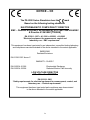
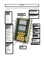
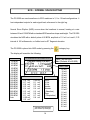
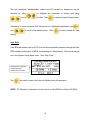
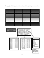
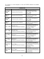
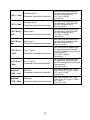
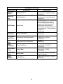
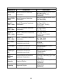
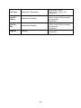
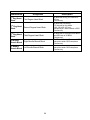
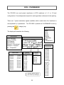
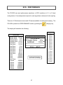
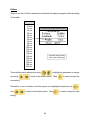
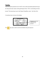
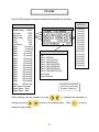
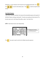
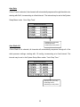
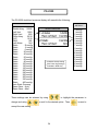
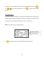
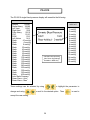
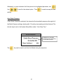
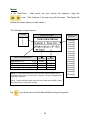
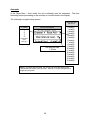
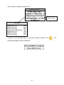
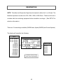
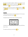
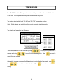
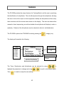
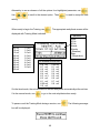
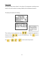
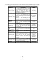
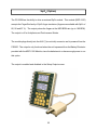
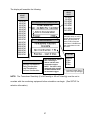
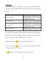
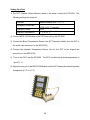
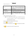
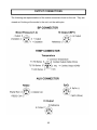
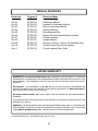
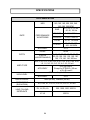
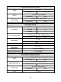
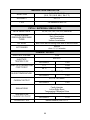
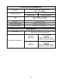
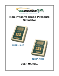
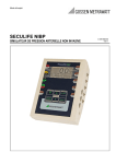
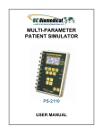
MULTI-PARAMETER
PATIENT SIMULATOR
PS-2200 SERIES
USER MANUAL
BC BIOMEDICAL
PS-2200 SERIES
TABLE OF CONTENTS
WARNINGS, CAUTIONS, NOTICES ............................................................................ ii
DESCRIPTION ............................................................................................................... 1
LAYOUT ......................................................................................................................... 7
ECG--NORMAL SINUS RHYTHM................................................................................ 14
ECG--ARRHYTHMIAS ................................................................................................. 16
ECG--PACEMAKER..................................................................................................... 25
ECG--PERFORMANCE ............................................................................................... 27
BLOOD PRESSURE .................................................................................................... 30
SWAN-GANZ .................................................................................................. 38
RESPIRATION ............................................................................................................. 42
TEMPERATURE .......................................................................................................... 44
TRAINING .................................................................................................................... 45
SETUP ......................................................................................................................... 50
POWER UP SETTINGS .............................................................................................. 53
SpO2 (OPTION) ........................................................................................................... 55
FETAL/MATERNAL (OPTION) .................................................................................... 56
CARDIAC OUTPUT (OPTION) .................................................................................... 59
OUTPUT CONNECTIONS ........................................................................................... 62
MANUAL REVISIONS .................................................................................................. 63
LIMITED WARRANTY ................................................................................................. 63
SPECIFICATIONS ....................................................................................................... 64
NOTES ......................................................................................................................... 68
i
WARNING - USERS
The PS-2200 Series are for use by skilled
technical personnel only.
WARNING - USE
The PS-2200 Series are intended for testing only
and should never be used in diagnostics,
treatment or any other capacity where they would
come in contact with a patient.
WARNING - CONNECTIONS
All connections to patients must be removed
before connecting the DUT to the PS-2200 Series.
A serious hazard may occur if the patient is
connected when testing with the PS-2200 Series.
CAUTION - MODIFICATIONS
The PS-2200 Series are intended for use within
the published specifications. Any application
beyond these specifications or any unauthorized
user modifications may result in hazards or
improper operation.
CAUTION - SERVICE
The PS-2200 Series are intended to be serviced
only by authorized service personnel.
Troubleshooting and service procedures should
only be performed by qualified technical
personnel.
CAUTION - INSPECTION
The PS-2200 Series should be inspected before
each use for obvious signs of abuse or wear.
The PS-2200 Series should not be used and
should be serviced if any parts are in question.
ii
CAUTION - CLEANING
Do not immerse. The PS-2200 Series should be
cleaned by wiping gently with a damp, lint-free
cloth. A mild detergent can be used if desired.
CAUTION - LIQUIDS
Do not submerge or spill liquids on the PS-2200
Series. Do not operate the PS-2200 Series if
exposed to fluid.
CAUTION - ENVIRONMENT
Exposure to environmental conditions outside
the specifications can adversely affect the
performance of the PS-2200 Series. Allow the PS2200 Series to acclimate to specified conditions
for at least 30 minutes before attempting to
operate them.
iii
NOTICE – CE
The PS-2200 Series Simulators bear the
mark
Based on the following testing standards:
ELECTROMAGNETIC COMPATIBILITY DIRECTIVE
EMC – Directive 89/336/EEC as amended by 92/31/EEC and 93/68/EEC
& Directive 91/263/EEC[TTE/SES]
EN 61326-1:1997 + A1:1998 + A2:2001 + A3:2003
“Electrical equipment for measurement, control and
laboratory use – EMC requirements”
This equipment has been type tested by an independent, accredited testing laboratory
and compliance was demonstrated to the above standard to the extent applicable.
EMISSIONS
Radiated Emissions
EN 61326:1997 Annex C
IMMUNITY– CLASS C
EN 61000-4-2:1995
EN 61000-4-3:2006
Electrostatic Discharge
Radiated Electric Field Immunity
LOW VOLTAGE DIRECTIVE
EC – Directive 73/23/EC
EN 61010-1:2001
“Safety requirements for electrical equipment for measurement, control, and
laboratory use – General requirements”
This equipment has been type tested and compliance was demonstrated
to the above standard to the extent applicable.
iv
NOTICE – SYMBOLS
Symbol Description
Caution
(Consult Manual for Further Information)
Center Negative
Per European Council Directive 2002/95/EC,
do not dispose of this product as unsorted
municipal waste.
NOTICE – ABBREVIATIONS
AHA
American Heart Association
ANSI
American National Standards Institute
BPM
Beats Per Minute
BrPM
Breaths Per Minute
C
Celsius
cc
cubic centimeters
°
ECG
F
degree(s)
Electrocardiogram
Fahrenheit
Hz
hertz
IEC
International Electrotechnical Commission
IBP
Invasive Blood Pressure
kHz
kilohertz
LED
Light Emitting Diode
L/min
Liters per minute
µV
microvolt(s)
mA
milliamp(s)
mm
millimeter(s)
mmHg
millimeter(s) of Mercury
mV
millivolt(s)
ms
millisecond(s)
NEDA
NSR
National Electronic Distributors Association
Normal Sinus Rhythm
Ω
ohm(s)
Lbs
pounds
RMS
Root Mean Square
USA
United States of America
V
VDC
Volt(s)
Volts Direct Current
v
NOTICE – DISCLAIMER
BC GROUP INTERNATIONAL, INC. WILL NOT BE RESPONSIBLE
FOR ANY INJURIES SUSTAINED DUE TO UNAUTHORIZED
EQUIPMENT MODIFICATIONS OR APPLICATION OF EQUIPMENT
OUTSIDE OF THE PUBLISHED INTENDED USE AND
SPECIFICATIONS.
NOTICE – DISCLAIMER
BC GROUP INTERNATIONAL, INC. RESERVES THE RIGHT TO
MAKE CHANGES TO ITS PRODUCTS OR SPECIFICATIONS AT
ANY TIME, WITHOUT NOTICE, IN ORDER TO IMPROVE THE
DESIGN OR PERFORMANCE AND TO SUPPLY THE BEST
POSSIBLE PRODUCT. THE INFORMATION IN THIS MANUAL HAS
BEEN CAREFULLY CHECKED AND IS BELIEVED TO BE
ACCURATE. HOWEVER, NO RESPONSIBILITY IS ASSUMED FOR
INACCURACIES.
NOTICE – CONTACT INFORMATION
BC BIOMEDICAL
BC GROUP INTERNATIONAL, INC.
3081 ELM POINT INDUSTRIAL DRIVE
ST. CHARLES, MO 63301
USA
1-800-242-8428
1-314-638-3800
www.bcgroupintl.com
[email protected]
PS-2200 Series User Manual
www.bcgroupintl.com
10/12
Copyright © 2012
Made in the USA
Rev 11
vi
BC BIOMEDICAL
PS-2200 SERIES
PATIENT SIMULATOR
The PS-2200 Family is a series of high end Microprocessor based Patient Simulators.
Each model provides ECG, Blood Pressure, Respiration and Temperature Simulation.
Models are available with one, two or four independent blood pressure outputs. All models
will support the Fetal/Maternal, SpO2 and Cardiac Output options.
The PS-2200 Family makes viewing and selecting the desired waveforms and parameters
quick and intuitive, with all operational information being available at the same time on two
cursor-based graphic displays, allowing for easy maneuvering through parameters and
scrolling through available options.
The following are highlights of some of the main features:
SIMPLE TO OPERATE
NO CODES TO REMEMBER OR ENTER
GRAPHICS DISPLAY WITH SIMULTANEOUS DETAILED STATUS OF
PARAMETERS AND SCROLLING CONTROL OF OPTIONS
DROP DOWN CHOICE SCREENS LIST ALL OPTIONS FOR PARAMETERS
SPECIAL POWER UP FEATURE ALLOWS THE USER TO CHOOSE TO USE
DEFAULT, LAST OR CUSTOM SETTINGS
AUTO SEQUENCES FOR BPM, STATIC-PRESSURE LEVELS AND
PERFORMANCE
10 UNIVERSAL PATIENT LEAD CONNECTORS
MINI-DIN CONNECTORS FOR BP CABLES
9 VOLT BATTERY POWER
% BATTERY LIFE DISPLAY
LOW BATTERY INDICATOR
AVAILABLE BATTERY ELIMINATOR
DISPLAY BACKLIGHT
FULL REMOTE OPERATION VIA RS-232
FLASH PROGRAMMABLE FOR UPGRADES
ECG NSR FUNCTIONS
The unit can produce a wide variety of ECG NSR simulations. The user simply selects the
parameters that match the desired output.
RATE:
30, 40, 45, 60, 80, 90, 100, 120, 140, 160, 180, 200, 220, 240, 260,
280, 300 BPM
AMPLITUDE (Lead II):
0.05, 0.10, 0.15, 0.20, 0.25, 0.30, 0.35, 0.40, 0.45, 0.50, 1.0, 1.5,
2.0, 2.5, 3.0, 3.5, 4.0, 4.5, 5.0 mV
1
S-T SEGMENT ELEVATION:
± 0, 0.05, 0.1, 0.2, 0.3, 0.4, 0.5, 0.6, 0.7, 0.8 mV
ARTIFACTS:
50 Hz, 60 Hz, MUSCLE, BASELINE WANDER, RESPIRATION
QRS INTERVAL:
ADULT (80 ms) OR PEDIATRIC (40 ms)
AUTOMATIC MODE
ARRHYTHMIA FUNCTIONS
The unit can simulate 36 different arrhythmias. For ease of selection, they are grouped
into four basic categories. Where applicable, both manual and automatic triggering of
the waveform is available.
36 DIFFERENT ARRHYTHMIAS
FOUR GENERAL GROUPS:
SUPRAVENTRICULAR
PREMATURE
VENTRICULAR
CONDUCTION
MANUAL AND AUTOMATIC TRIGGERING
PACEMAKER FUNCTIONS
Seven different pacemaker waveforms may be simulated. Additionally, the width and
amplitude of the pacer pulse may be selected.
WAVEFORMS:
ATRIAL PACER, ASYNCHRONOUS, NON-CAPTURE,
NON-FUNCTION, DEMAND - OCCASIONAL,
DEMAND – FREQUENT, AV - SEQUENTIAL
PULSE HEIGHT:
1, 2, 3, 4, 5, 6, 7, 8, 9, 10 mV
PULSE WIDTH:
0.1, 0.5, 1.0, 1.5, 2.0 ms
ECG-PERFORMANCE FUNCTIONS
The unit will generate Sine, Square, Triangular and Pulse waveforms with adjustable
amplitudes for performance testing. A special Automatic mode is available to auto
sequence through the entire range of waveforms. Also, a R-Wave (Havertriangle)
waveform may be selected with separate amplitude and width settings.
SINE:
0.1, 0.5, 5, 10, 40, 50, 60, 100 Hz
2
SQUARE:
0.125, 2.0 Hz
TRIANGLE:
2.0, 2.5 Hz
PULSE:
30, 60, 120 BPM; 60 ms WIDTH
AMPLITUDE (Lead II):
0.05, 0.10, 0.15, 0.20, 0.25, 0.30, 0.35, 0.40, 0.45, 0.50, 1.0, 1.5,
2.0, 2.5, 3.0, 3.5, 4.0, 4.5, 5.0 mV
AUTOMATIC MODE
R WAVE RATE:
30, 60, 80, 120, 200, 250 BPM
R WAVE WIDTH:
8, 10, 12, 20, 30, 40, 50, 60, 70, 80, 90, 100, 110, 120, 130, 140,
150, 160, 170, 180, 190, 200 ms
R WAVE AMPLITUDE (Lead II):
0.05, 0.10, 0.15, 0.20, 0.25, 0.30, 0.35, 0.40, 0.45, 0.50, 1.0, 1.5, ,
2.0, 2.5, 3.0, 3.5, 4.0, 4.5, 5.0 mV
RESPIRATION
Respiration is simulated at 8 different rates, with the ability to select from 4 Baseline
Impedances, the Lead in which it will appear, and the Delta Ohms (amplitude) of the signal.
Additionally, an Apnea period may be selected.
RATE:
15, 20, 30, 40, 60, 80, 100, 120 BrPM
BASELINE IMPEDANCE:
500, 1000, 1500, 2000 OHMS
LEAD:
LA or LL
DELTA IMPEDANCE:
0.1, 0.2, 0.5, 1.0, 2.0, 3.0 OHMS
APNEA:
12, 22 and 32 SECONDS PLUS CONTINUOUS
BLOOD PRESSURE
There is one or more (dependent on model) Blood Pressure simulation channels.
Both static and dynamic invasive pressures are simulated. In the static mode, the BP
outputs are fixed at the selected level or sequenced through the list using the Automatic
mode selection.
In the Dynamic mode, the selected waveform is synchronized with the ECG and provides a
continuous output. Additionally, a Respiration Artifact may be added.
3
A special Swan-Ganz mode is available that will allow Manual or Automatic simulation of
that sequence.
Each channel has independent settings.
STATIC:
-10, -5, 0, 20, 40, 50, 60, 80, 100, 150, 160, 200, 240,
250, 300, 320, 400 mmHg
AUTOMATIC STATIC PRESSURE MODE
8 DYNAMIC WAVEFORMS
RESPIRATION ARTIFACT:
0 to 16 mmHg
SENSITIVITY:
5 or 40 µV/V/mmHg
SWAN-GANZ SIMULATION
7 PRESET STATIC GROUPS (MODEL PS-2240 ONLY)
TEMPERATURE
The unit will simulate seven temperatures. This is done by providing the necessary ohmic
levels for both the YSI 400 and 700 Series thermistors.
YSI 400 SERIES and 700 SERIES SIMULATION
SELECTIONS:
0, 24, 30, 35, 37, 40, 42 °C
(32.0, 75.2, 86.0, 95.0, 98.6, 104.0, 107.6 °F)
LEAD TEST FUNCTION
The unit provides a set of test terminals to quick check leads. It will determine if a lead has
less than 1000 Ohms resistance.
TRAINING
The unit has a special training mode that may be used to aid users in practicing the
identification of arrhythmias. A series of settings allows the feature to be customized to fit
the exact training requirement.
TIMER:
MANUAL, 10, 15, 20, 25, 30 SEC
RANDOMIZER:
OFF,ON
ARRHYTHMIAS:
ALL,SUBSET
4
SPO2 SIMULATION (Optional)
When used with the MSP-2100 external module and FingerSim family of SpO 2 finger
simulators, the system will provide a pulse synchronized SpO2 output for all NSR rates.
RATE:
30, 40, 45, 60, 80, 90, 100, 120, 140, 160, 180, 200, 220,
240, 260, 280, 300 BPM
SpO2 OUTPUT:
80, 90, 97 %
FETAL/MATERNAL (Option)
This option provides a combination of fetal and maternal ECG waveforms with and without
contractions. Additionally, it provides an Intrauterine-Pressure (IUP) waveform.
FETAL HEART RATE:
60, 90, 120, 140, 150, 210, 240 BPM
IUP PERIOD:
SINGLE CONTRACTION (MANUAL)
2, 3, 5, MIN (AUTO)
FHR (DURING CONTRACTION):
UNIFORM DECELERATION
EARLY DECELERATION
LATE DECELERATION
UNIFORM ACCELERATION
CARDIAC OUTPUT (Option)
When used with the MCO-2100 External Module, this option provides both the hardware
and software to simulate Cardiac Output waveforms for testing devices that utilize Baxter –
Edwards type catheters.
INJECTATE TEMPERATURE:
0, 24 °C
INJECTATE FLOW:
2.5, 5.0, 10.0 L/MIN
OTHER OUTPUTS:
FAULTY – INJECTATE
LEFT-TO-RIGHT SHUNT
CALIBRATED TEMPERATURE PULSE
5
OPTIONAL ACCESSORIES
BC20-21100
BC20-21101
BC20-02300
BC20-02400
MSP-2100
FingerSim™ KIT
FingerSim™ SET
BC20-30107
BC20-41337
BC20-41339
BATTERY ELIMINATOR (USA Version)
BATTERY ELIMINATOR (Euro Version)
FETAL / MATERNAL OPTION
CARDIAC OUTPUT OPTION
PULSE OXIMETRY MODULE (ALLOWS PS-2200 TO
SIMULATE SpO2 OUTPUT WHEN USED WITH
FingerSims™)
COMPLETE STARTER KIT (INCLUDES 80%, 90% AND
97% FingerSims™, FingerSim™ HOLDER, AND
CARRYING CASE)
REPLACEMENT KIT (INCLUDES 80%, 90% AND 97%
FingerSims™ ONLY)
SOFT-SIDED CARRYING CASE
COMMUNICATION CABLE (MINI DIN M TO DB-9F)
COMMUNICATION CABLE (USB TO DB-9M)
INVASIVE BLOOD PRESSURE CABLES
FOR A COMPLETE LIST CONSULT THE BC GROUP WEBSITE AT
WWW.BCGROUPINTL.COM
TEMPERATURE SIMULATION CABLES
BC20-41333
UT-1 YSI-400
BC20-41334
UT-2 YSI-700
CARDIAC OUTPUT CABLES
BC20-41335
HP INJECTATE CABLE ASSEMBLY
BC20-41336
HP TEMP CABLE
6
LAYOUT
This section looks at the layout of a PS-2200 and gives descriptions of the elements that
are present.
10 Universal
Patient Lead
Connectors:
RA R
LA
L
RL(-) N
LL
F
V1 C1
V2 C2
V3 C3
V4 C4
V5 C5
V6 C6
LCD Graphical Display 1:
Shows Parameters for
ECG, Respiration and
Temperature
Lead Continuity
Test Connections
6-Pin Mini-DIN
Plug Connectors
for Blood Pressure
Cables
7 Light Touch Keys
for Selecting
Parameters and
Settings:
LEFT and RIGHT
Curved Arrows for
Moving through
Parameters
UP and DOWN
Arrows for Scrolling
through Options
ENTER for
Selecting Option
CHOICES for
Displaying
Submenu of All
Options for a Given
Parameter
QUIT for Returning
to Previous Status
8 Light Touch Keys
for Category
Selection:
Normal Sinus
Rhythm
Arrhythmias
Pacemaker
Performance
Fetal/Maternal
Cardiac Output
Training
Setup
LCD Graphical Display 2:
Shows Parameters for
Blood Pressure
8-Pin Mini-DIN
Plug Connector for
Temperature/CO
Cable
7-Pin Mini-DIN
Plug Connector
for Aux Functions
Back Light Key for
turning on and off the
backlight
Battery Eliminator Jack
Power Key for
Turning Unit
On and Off
7
General Operation
The unit is controlled by 17 light touch keys. They allow the user to move around within the
displayed parameters, select the desired options, choose a specific category and control
the setup and power for the unit. When a key is depressed there is an audio click when it
is accepted, or a razz tone if the key is invalid.
Two graphics LCD displays provide the user with information about the current status of
the ECG, Respiration, Temperature and Blood Pressure settings. The
keys
move the block cursor through the displayed information; highlighting the parameter
available for selection. The
parameter.
keys change the options for the highlighted
The cursor begins flashing if the parameter has been changed.
key selects the changed option. The
The
key returns to the previous state,
without any changes being made.
To make option selection even easier and to make memorizing and using codes
unnecessary, the
key will bring up a screen that displays all the options for the
selected parameter. The
and
keys can then be used to quickly
scroll through the available options and select the desired setting.
Seven category keys allow for quick setting of output waveforms. The
,
,
category. The
,
and
or
,
,
keys move the display directly to the selected
keys can then be used to scroll through and select
the desired settings.
8
The
key opens a screen that allows the user to select the unit’s general output
settings, as well as setup for the system.
Category Keys
The
The
key enters the NSR category.
key enters the arrhythmia category and changes the first line in the display to
the first arrhythmia choice.
The
key enters the pacemaker category and changes the first line in the display to
the first pacemaker waveform choice.
The
key enters the machine performance testing category and changes the first
line in the display to the first performance waveform choice.
The
key opens a screen that allows the user to set the conditions for and start
the optional Fetal/Maternal mode. (Optional)
The
key opens a screen that allows the user to set the conditions for and start
the optional Cardiac Output mode. (Optional)
The
key opens a screen that allows the user to set the conditions for and start
the special training mode.
9
Power Key
The
key turns the unit on and off. To turn off the unit, the key must be held for 1
second.
Backlight
The Graphic LCD display may be viewed with or without the backlight. Depressing any key
will activate the backlight. However, since the backlight will drain the battery if left on, it will
automatically shut off after a few seconds when running on battery power. (Note: This time
is selectable in the System Setup screen).
The intensity of the backlight can be adjusted in the System Setup screen to conserve
battery life.
The
key is provided to toggle the backlight on or off at any time.
NOTE: The backlight parameter in the System Setup screen may be set to Off, 1-30 sec
Timed or Manual.
ECG Waveforms
The microprocessor has stored in its memory all of the digitalized waveforms. It sends the
individual lead waveforms to D/A converters, which generate accurate analog
representations. The waveforms are then sent through resistor networks, developing the
appropriate signals on the output terminals.
10
Respiration
Respiration waveforms are provided that have adjustable rates from 15 to 120 BrPM
(Breaths Per Minute) as well as an Apnea (0 BrPM) setting. The signal is generated by
a variation in the impedance in either the LL or LA lead (selectable). The amplitude is
settable from .5 to 3.0 ohms.
Blood Pressure
There are one, two or four 6-pin mini-DIN plug connectors on the right side of the unit
for connection of the Blood Pressure cables. Full blood pressure simulation is available
through these connectors. The circuits are totally isolated.
Temperature
There is an 8-pin mini-DIN plug connector on the right side of the unit for connection of
a Temperature cable. Temperatures are simulated for both YSI 400 and YSI 700 probe
types. There are seven different temperatures selectable for each.
Universal Patient Lead Connectors
The 10 Universal Patent Lead Connectors allow for 12 lead ECG simulation with
independent outputs. AHA and IEC color-coded labels are located on the face of the unit
to aid in connecting the corresponding U.S. and International Patient Leads.
11
AHA Label
IEC Label
Description
RA
R
Right Arm
LA
L
Left Arm
RL
N
Right Leg
(reference or ground)
LL
F
Left Leg
V1
V2
V3
V4
V5
V6
C1
C2
C3
C4
C5
C6
V Leads (V1-V6)
(U.S. and Canada)
also referred to as pericardial,
precordial or unipolar chest leads
Chest Leads (C1-C6)
(International)
High Level Output (+)
A high level ECG output signal (200 x Amplitude Setting) is available in the BP1 6-Pin
mini-DIN connector.
Auto Power Off
The unit may be programmed to automatically turn off after a selected number of minutes
of no key activity to conserve the battery. (Note: This time is selectable in the System
Setup screen).
Power Supply
The unit utilizes two 9 Volt Alkaline Batteries in the rear battery compartment. When the
unit detects a LOW BATTERY condition (5% Battery Life), a warning window will appear
once per minute to alert the user. The
key may be used to clear this window and
12
continue use of the unit. If the battery is not replaced before the battery reaches a critical
level (0 % Battery Life), the unit will shut down. (The percentage of life left in the batteries
can be viewed in the System Setup screen.)
Battery Eliminator
The unit has a 2.1 mm jack for connecting the Battery Eliminator (Optional).
Note: The Battery Eliminator will not charge the battery.
Power Up Settings
The unit may be setup to turn on using either the factory default settings, the same settings
that it had when last turned off or a custom set of parameters as previously saved by the
user (See Power Up Settings section for details).
Automatic Modes
The ECG NSR Rate, ECG Performance and Static Blood Pressure Parameters all allow
for an automatic setting. In each of these, the unit will sequence through the full range of
settings automatically at a fixed rate (as selected in the Auto Step Time Parameter). When
in this mode, the time remaining in each step is displayed.
The
key may be used to manually advance to the next step. The
used to terminate the mode.
13
key is
ECG – NORMAL SINUS RHYTHM
The PS-2200 can send waveforms to ECG machines in 3, 5 or 12 lead configurations. It
has independent outputs for each signal lead, referenced to the right leg.
Normal Sinus Rhythm (NSR) occurs when the heartbeat is normal, beating at a rate
between 50 and 100 BPM with a standard QRS waveform shape and height. The PS-2200
simulates the NSR with a default pulse of 80 BPM, amplitude of 1.0 mV on Lead II, P-R
interval of 160 milliseconds, no Artifact and no ST Segment elevation.
The PS-2200 is placed into NSR mode by pressing the
category key.
The display will resemble the following:
PATIENT MODE
RATE
30 BPM
40 BPM
45 BPM
60 BPM
80 BPM*
90 BPM
100 BPM
120 BPM
140 BPM
160 BPM
180 BPM
200 BPM
220 BPM
240 BPM
260 BPM
280 BPM
300 BPM
Auto
ECG/RESPIRATION/TEMPERATURE
Adult* (80 mS QRS)
Ped (Pediatric 40 mS QRS)
AMPLITUDE
ARTIFACT
ST SEGMENT ELEVATION
-0.8 mV
-0.7 mV
-0.6 mV
-0.5 mV
-0.4 mV
-0.3 mV
-0.2 mV
-0.1 mV
-0.05 mV
0.0 mV*
0.05 mV
0.1 mV
0.2 mV
0.3 mV
0.4 mV
0.5 mV
0.6 mV
0.7 mV
0.8 mV
None*
50 Hz
60 Hz
Muscle
Wander
(Baseline)
Resp
(Respiration)
* Indicates Default Setting
(See Power Up Settings)
14
.05 mV
.10 mV
.15 mV
.20 mV
.25 mV
.30 mV
.35 mV
.40 mV
.45 mV
.50 mV
1.0 mV*
1.5 mV
2.0 mV
2.5 mV
3.0 mV
3.5 mV
4.0 mV
4.5 mV
5.0 mV
The rate, amplitude, adult/pediatric, artifact and ST elevation or depression can be
selected by using
to highlight the parameter to change and using
to scroll to the desired value. Then
is used to accept the new setting.
Alternately, to see a submenu of all the options for a highlighted parameter, use
Use
to scroll to the desired option. Then
.
is used to accept the new
setting.
Auto Rate
If the BPM parameter is set to AUTO, the unit will automatically sequence through all of the
BPM settings, starting with 30 BPM, incrementing at a fixed interval. The interval may be
set in the System Setup Menu under “Auto Step Time”.
Displays time (seconds)
remaining before
advancing to next rate.
The
key can be used to exit the Auto Mode during the sequence.
NOTE: ST Elevation or Depression is only active in Adult NSR at or below 180 BPM.
15
ECG – ARRHYTHMIAS
The PS-2200 can send Arrhythmia waveforms to ECG machines in 3, 5 or 12-lead
configurations. It has independent outputs for each signal lead, referenced to the right leg.
There are 36 Arrhythmias available that model abnormal heartbeats. The PS-2200 is
placed into ARRHYTHMIA mode by pressing the
16
category key.
The top portion of the display shows the currently enabled arrhythmia group and selection,
selectable from:
Premature
Atrial PAC - Auto*
Atrial PAC - Man
Nodal PNC - Auto
Nodal PNC - Man
PVC 1 - Auto
PVC 1 - Man
PVC 1 Early - Auto
PVC 1 Early - Man
PVC 1 R on T - Auto
PVC 1 R on T - Man
PVC 2 - Auto
PVC 2 - Man
PVC 2 Early - Auto
PVC 2 Early - Man
PVC 2 R on T - Auto
PVC 2 R on T - Man
Multifocal PVCs - Auto
Multifocal PVCs - Man
Supraventricular
Atrial Fib - Coarse
Atrial Fib - Fine
Atrial Flutter
Atrial Tach
Paroxysmal Atrial Tach
Supravent Tach
Sinus Arrhythmia
Missed Beat - Auto
Missed Beat - Man
Nodal Rhythm
Ventricular
Pair of PVCs - Auto
Pair of PVCs - Man
Run of 5 PVCs - Auto
Run of 5 PVCs - Man
Run of 11 PVCs - Auto
Run of 11 PVCs - Man
6 PVCs per Min
12 PVCs per Min
24 PVCs per Min
Freq Multifocal PVCs
Bigeminy
Trigeminy
Vent Tach
Vent Fib – Coarse
Vent Fib – Fine
Asystole
Conduction
st
1 Deg Heart Block
nd
2 Deg Heart Block
rd
3 Deg Heart Block
Rt Bundle Branch Block
Lf Bundle Branch Block
ARRHYTHMIA GROUP
ARRHYTHMIA
AMPLITUDE
.05 mV
.10 mV
.15 mV
.20 mV
.25 mV
.30 mV
.35 mV
.40 mV
.45 mV
.50 mV
1.0 mV*
1.5 mV
2.0 mV
2.5 mV
3.0 mV
3.5 mV
4.0 mV
4.5 mV
5.0 mV
ST SEGMENT ELEVATION
-0.8 mV
-0.7 mV
-0.6 mV
-0.5 mV
-0.4 mV
-0.3 m V
-0.2 mV
-0.1 mV
-0.05 mV
0.0 mV*
0.05 mV
0.1 mV
0.2 mV
0.3 mV
0.4 mV
0.5 mV
0.6 mV
0.7 mV
0.8 mV
ARTIFACT
None*
50 Hz
60 Hz
Muscle
Wander
(Baseline)
Resp
(Respiration)
* Indicates
Default Setting
(See Power Up
Settings)
17
The grouping, arrhythmias and amplitude can be selected by using
highlight the parameter to change and using
Then
to
to scroll to the desired option.
is used to accept the new setting.
Alternately, to see a submenu of all the options for a highlighted parameter, use
Use
to scroll to the desired option. Then
is used to accept the new
setting.
NOTE: While in the Arrhythmia Group choice screen, the
key may be used for a
second time to jump directly to the arrhythmias choices for that group.
Auto/Manual
There are 12 arrhythmias that have both Automatic and Manual versions. Both versions
output the same waveform; however, in the Manual version, the arrhythmia is triggered
each time
is depressed. In the Auto versions, the arrhythmia is automatically
triggered periodically.
18
The following is a brief description of how the PS-2200 simulates the available
Arrhythmias:
Abbreviation
PREMATURE
Arrhythmia
Atrial PAC
– Auto
Premature Atrial Contraction
Atrial PAC
– Man
Premature Atrial Contraction
Nodal PNC
– Auto
Premature Nodal Contraction
Nodal PNC
– Man
Premature Nodal Contraction
PVC 1 – Auto
Standard Type 1
Premature Ventricular Contraction
PVC 1 – Man
Standard Type 1
Premature Ventricular Contraction
PVC 1 Early Auto
Early Type 1
Premature Ventricular Contraction
PVC 1 Early Man
Early Type 1
Premature Ventricular Contraction
PVC 1 R on T
– Auto
R on T Type 1
Premature Ventricular Contraction
PVC 1 R on T
– Man
R on T Type 1
Premature Ventricular Contraction
19
Description
NSR of 80 BPM with Periodic
Abnormal 25 % early P waves
(PAC, 7 NSR)
(Continuous)
NSR of 80 BPM with Periodic
Abnormal 25 % early P waves
(One-Time event)
NSR of 80 BPM with Periodic
Abnormal 25 % early Nodal beat
(PNC, 7 NSR)
(Continuous)
NSR of 80 BPM with Periodic
Abnormal 25 % early Nodal beat
(One-Time event)
NSR of 80 BPM with periodic left
focus premature ventricular beats
with 20% premature timing
(PVC Type 1, 9 NSR)
(Continuous)
NSR of 80 BPM with periodic left
focus premature ventricular beats
with 20% premature timing
(One-Time event)
NSR of 80 BPM with periodic left
focus premature ventricular beats
with 33% premature timing
(PVC Type 1, 9 NSR)
(Continuous)
NSR of 80 BPM with periodic left
focus premature ventricular beats
with 33% premature timing
(One-Time event)
NSR of 80 BPM with periodic left
focus premature ventricular beats
with 65% premature timing, placing R
on the previous T
(PVC Type 1, 9 NSR)
(Continuous)
NSR of 80 BPM with periodic left
focus premature ventricular beats
with 65% premature timing, placing R
on the previous T
(One-Time event)
PVC 2 – Auto
Standard Type 2
Premature Ventricular Contraction
PVC 2 – Man
Standard Type 2
Premature Ventricular Contraction
PVC 2 Early Auto
Early Type 2
Premature Ventricular Contraction
PVC 2 Early Man
Early Type 2
Premature Ventricular Contraction
PVC 2 R on T
– Auto
R on T Type 2
Premature Ventricular Contraction
PVC 2 R on T
– Man
R on T Type 2
Premature Ventricular Contraction
Multifocal
PVCS – Auto
Multifocal
Premature Ventricular Contraction
Multifocal
PVCS – Man
Multifocal
Premature Ventricular Contractions
20
NSR of 80 BPM with periodic right
focus premature ventricular beats
with 20% premature timing
(PVC Type 2, 9 NSR)
(Continuous)
NSR of 80 BPM with periodic right
focus premature ventricular beats
with 20% premature timing
(One-Time event)
NSR of 80 BPM with periodic right
focus premature ventricular beats
with 33% premature timing
(PVC Type 2, 9 NSR)
(Continuous)
NSR of 80 BPM with periodic right
focus premature ventricular beats
with 33% premature timing
(One-Time event)
NSR of 80 BPM with periodic right
focus premature ventricular beats
with 65% premature timing, placing R
on the previous T
(PVC Type 2, 9 NSR)
(Continuous)
NSR of 80 BPM with periodic right
focus premature ventricular beats
with 65% premature timing, placing R
on the previous T
(One-Time event)
NSR of 80 BPM with Type 1 and
Type 2 PVCs (PVC Type 1, 2 NSR,
PVC Type 2, 2 NSR)
(Continuous)
NSR of 80 BPM with Type 1 and
Type 2 PVCs (PVC Type 1, 2 NSR,
PVC Type 2)
(One-Time event)
Abbreviation
SUPRAVENTRICULAR
Arrhythmia
Description
Absence of P-wave, irregular P-R
interval rate and a high level signal
(Continuous)
Absence of P-wave, irregular P-R
interval rate and a low level signal
(Continuous)
Repeating sequence of 5 atrial beats
and 1 ventrical beat for twelve
seconds, followed by a repeating
sequence of 3 atrial beats and 1
ventrical beat for six seconds,
followed by a repeating sequence of
2 atrial beats and 1 ventrical beat for
six seconds
(Continuous)
Atrial Fib –
Coarse
Artial Fibrillation
Atrial Fib –
Fine
Artial Fibrillation
Atrial Flutter
Atrial Flutter
Atrial Tach
Atrial Tachycardia
160 BPM
(Continuous)
Paroxysmal
Atrial Tach
Paroxysmal Atrial Tachycardia
160 BPM for five seconds
80 BPM for ten seconds
(Continuous)
Supravent
Tach
Supraventricular Tachycardia
200 BPM
(Continuous)
Sinus
Arrhythmia
Sinus Arrhythmia
Missed Beat
– Auto
Missed Beat
Missed Beat
– Man
Nodal
Rhythm
Normal beats at a fluctuating rate
from 60 BPM to 100 BPM
(Continuous)
NSR of 80 BPM with a missed beat
(Missed Beat, 36 NSR)
(Continuous)
Missed Beat
NSR of 80 BPM with a missed beat
(One-Time Event)
Nodal Rhythm
60 BPM with very short P-R interval
(Continuous)
21
Abbreviation
VENTRICULAR
Arrhythmia
Pair of PVCs
– Auto
Pair of Premature Ventricular
Contractions
Pair of PVCs
– Man
Pair of Premature Ventricular
Contractions
Run of 5
PVCs – Auto
Run of 5 Premature Ventricular
Contractions
Run of 5
PVCs – Man
Run of 5 Premature Ventricular
Contractions
Run of 11
PVCs – Auto
Run of 11 Premature Ventricular
Contractions
Run of 11
PVCs – Man
Run of 11 Premature Ventricular
Contractions
6 PVCs per
Min
6 Premature Ventricular
Contractions per minute
12 PVCs per
Min
12 Premature Ventricular
Contractions per minute
24 PVCs per
Min
24 Premature Ventricular
Contractions per minute
Freq
Multifocal
PVCs
Frequent Multifocal Premature
Ventricular Contractions
Bigeminy
Bigeminal Rhythm
Trigeminy
Trigeminal Rhythm
22
Description
NSR of 80 BPM with Periodic Group
of 2 Type 1 PVCs
(2 PVC Type 1, 36 NSR)
(Continuous)
NSR of 80 BPM with Periodic Group
of 2 Type 1 PVCs
(One-Time Event)
NSR of 80 BPM with periodic group
of 5 Type 1 PVCs
(5 PVC Type 1, 36 NSR)
(Continuous)
NSR of 80 BPM with periodic group
of 5 Type 1 PVCs
(One-Time event)
NSR of 80 BPM with periodic group
of 11 Type 1 PVCs
(11 PVC Type 1, 36 NSR)
(Continuous)
NSR of 80 BPM with periodic group
of 11 Type 1 PVCs
(One-Time event)
NSR of 80 BPM with 6 Type 1 PVCs
per minute
(Continuous)
NSR of 80 BPM with 12 Type 1
PVCs per minute
(Continuous)
NSR of 80 BPM with 24 Type 1
PVCs per minute
(Continuous)
NSR of 80 BPM with every fourth
beat being an alternating Type 1 and
Type 2 PVC
(Continuous)
NSR of 80 BPM with every other beat
a Type 1 PVC
(Continuous)
NSR of 80 BPM with every third beat
a Type 1 PVC
(Continuous)
Vent Tach
Ventricular Tachycardia
Vent Fib –
Coarse
Ventricular Fibrillation
Vent Fib –
Fine
Ventricular Fibrillation
Asystole
Asystole
160 BPM, No P-wave,
Beats similar to Type 1 PVC
(Continuous)
Irregular waveform with no real
P-wave or clear R-R interval and a
high signal level
(Continuous)
Irregular waveform with no real
P-wave or clear R-R interval and a
low signal level
(Continuous)
Flat line signal
(Continuous)
23
Abbreviation
CONDUCTION
Arrhythmia
1st Deg Heart
Block
First Degree Heart Block
2nd Deg Heart
Block
Second Degree Heart Block
3rd Deg Heart
Block
Third Degree Heart Block
Rt Bundle
Branch Block
Right Bundle Branch Block
Lf Bundle
Branch Block
Left Bundle Branch Block
24
Description
80 BPM with a long P-R interval of
250 ms
(Continuous)
80 BPM with increasing
P-R interval for four beats
(160, 220, 400, 470 ms)
followed by a P wave without a QRS
(Continuous)
80 BPM with P wave rate of 80 BPM
and QRS rate of 30 BPM
(Continuous)
80 BPM with Normal P-wave and P-R
interval but wider QRS complexes
(Continuous)
80 BPM with Normal P-wave and P-R
interval but wider QRS complexes
(Continuous)
ECG – PACEMAKER
The PS-2200 can send paced waveforms to ECG machines in 3, 5 or 12 lead
configurations. It has independent outputs for each signal lead, referenced to the right leg.
There are 7 paced simulation signals available which model when the heartbeat is
accompanied by a pacemaker. The PS-2200 is placed into PACEMAKER mode by
pressing the
category key.
ARTIFACT
The display will resemble the following:
WAVEFORM
Atrial (80 BPM)*
Async (75 BPM)
Non-Capture
Non-Function
Demand – Occasional
Demand – Frequent
AV – Sequential
AMPLITUDE
.05 mV
.10 mV
.15 mV
.20 mV
.25 mV
.30 mV
.35 mV
.40 mV
.45 mV
.50 mV
1.0 mV*
1.5 mV
2.0 mV
2.5 mV
3.0 mV
3.5 mV
4.0 mV
4.5 mV
5.0 mV
ECG/RESPIRATION/TEMPERATURE
None*
50 Hz
60 Hz
Muscle
Wander
(Baseline)
Resp
(Respiration)
ST SEGMENT
ELEVATION
PULSE
AMPLITUDE
PULSE
WIDTH
1 mV
2 mV
3 mV
4 mV
5 mV*
6 mV
7 mV
8 mV
9 mV
10 mV
0.1 ms
0.5 ms
1.0 ms*
1.5 ms
2.0 ms
* Indicates Default Setting
(See Power Up Settings)
25
-0.8 mV
-0.7 mV
-0.6 mV
-0.5 mV
-0.4 mV
-0.3 mV
-0.2 mV
-0.1 mV
-0.05 mV
0.0 mV*
0.05 mV
0.1 mV
0.2 mV
0.3 mV
0.4 mV
0.5 mV
0.6 mV
0.7 mV
0.8 mV
The pacemaker rhythms and signals can be selected by using
the parameter to change and using
to highlight
to scroll to the desired option. Then
is used to accept the new setting.
Alternately, to see a submenu of all the options for a highlighted parameter, use
Use
to scroll to the desired option. Then
.
is used to accept the new
setting.
The following is a brief description of how the PS-2200 simulates the available Pacemaker
Waveforms:
Abbreviation
PACEMAKER
Waveform
Atrial Pacer
Atrial Pacemaker Wave
Asynchronous
Asynchronous Pacemaker Wave
Demand –
Occasional
Demand –
Frequent
Ventricular Pacemaker Wave
with Periodic Non-Response
Ventricular Pacemaker Wave
with no Heart Response
Demand Pacemaker Wave with
Occasional Sinus Beats
Demand Pacemaker Wave with
Frequent Sinus Beats
AV – Sequential
AV-Sequential Pacemaker Wave
Non-Capture
Non-Function
26
Description
80 BPM with Pacer Pulse at the start
of each P wave
75 BPM with Pacer Pulse at the start
of each QRS wave and no P wave
75 BPM Ventricular Paced beats
with every tenth beat not responding
75 BPM Ventricular Paced beats
with no heart response
20 NSR beats followed by 20
Ventricular Paced beats
40 NSR beats followed by 40
Ventricular Paced beats
75 BPM with Pacer Pulse at the start
of both the P and QRS waves
ECG – PERFORMANCE
The PS-2200 can send performance waveforms to ECG machines in 3, 5 or 12-lead
configurations. It has independent outputs for each signal lead, referenced to the right leg.
There are 15 Performance waves and 6 R-waves available for testing and verifying. The
PS-2200 is placed into PERFORMANCE mode by pressing the
category key.
The display will resemble the following:
AMPLITUDE
T
WAVEFORM
Square Wave .125 Hz
Square Wave
2 Hz*
Triangle Wave
2 Hz
Triangle Wave 2.5 Hz
Sine Wave
0.1 Hz
Sine Wave
0.5 Hz
Sine Wave
5 Hz
Sine Wave
10 Hz
Sine Wave
40 Hz
Sine Wave
50 Hz
Sine Wave
60 Hz
Sine Wave
100 Hz
Pulse
30 BPM
Pulse
60 BPM
Pulse
120 BPM
Auto Wave
R-Wave
30 BPM
R-Wave
60 BPM
R-Wave
80 BPM
R-Wave
120 BPM
R-Wave
200 BPM
R-Wave
250 BPM
ECG/RESPIRATION/TEMPERATURE
* Indicates Default Setting
(See Power Up Settings)
27
.05 mv
.10 mv
.15 mv
.20 mv
.25 mv
.30 mv
.35 mv
.40 mv
.45 mv
.50 mv
1.0 mv*
1.5 mv
2.0 mv
2.5 mv
3.0 mv
3.5 mv
4.0 mv
4.5 mv
5.0 mV
R-Wave
When one of the 6 R-Wave waveforms is selected, the display changes to allow the setting
of the width.
WIDTH
8 ms
10 ms*
12 ms
20 ms
30 ms
40 ms
50 ms
60 ms
70 ms
80 ms
90 ms
100 ms
120 ms
130 ms
140 ms
150 ms
160 ms
170 ms
180 ms
190 ms
200 ms
ECG/RESPIRATION/TEMPERATURE
* Indicates Default Setting
(See Power Up Settings)
These widths can be selected by using
and using
to highlight the parameter to change
to scroll to the desired option. Then
is used to accept the
new setting.
Alternately, to see a submenu of all the options for a highlighted parameter, use
Use
to scroll to the desired option. Then
setting.
28
.
is used to accept the new
Auto Wave
If the Performance parameter is set to AUTO, the unit will automatically sequence through
all of the performance waves, starting with Square Wave .125 Hz, incrementing at a fixed
interval. The interval may be set in the System Setup Menu under “Auto Step Time”.
A countdown timer is shown in the display:
Displays time (seconds)
remaining before
advancing to next
waveform.
The
key can be used to exit the Auto Mode during the sequence.
29
BLOOD PRESSURE
NOTE: The Transducer Sensitivity (5 or 40 µV/V/mmHg) must be set to correlate with the
monitoring equipment before simulation can begin. (See SETUP for selection information).
The PS-2200 series offers one, two or four Blood Pressure Channels and will simulate the
set Blood Pressure wave during ECG waveforms where it occurs.
Model Number
Blood Pressure Channels
PS-2210
1 Blood Pressure Output
PS-2220
2 Blood Pressure Outputs
PS-2240
4 Blood Pressure Outputs
NOTE: All settings are available on each output.
There are 16 Blood Pressure settings available, 17 static and 8 dynamic. Each of the
dynamic waveforms will synchronize with the NSR rate or arrhythmia selection.
Both an automatic and manual Swan-Ganz simulation are also available.
Each of the models has a slightly different display to optimize the individual features.
30
PS-2240
The PS-2240 quad blood pressure display will resemble the following:
RESPIRATION
ARTIFACT
WAVEFORM
Arterial
120/80
Radial Artery 120/80
Left Vent
120/0
Right Vent
25/0
Pulm Artery
25/10
CVP
15/10
PAW
10/2
Left Atrium
14/4
Static
-10 mmHg
Static
-5 mmHg
Static
0 mmHg*
Static
20 mmHg
Static
40 mmHg
Static
50 mmHg
Static
60 mmHg
Static
80 mmHg
Static
100 mmHg
Static
150 mmHg
Static
160 mmHg
Static
200 mmHg
Static
240 mmHg
Static
250 mmHg
Static
300 mmHg
Static
320 mmHg
Static
400 mmHg
Auto Static Pressure
+
Swan-Ganz – Auto
Swan-Ganz – Man+
BLOOD PRESSURE
GROUP SETTINGS
Off*
Set 0 (0/0/0/0)
Set 1 (-10/-10/-5/-5)
Set 2 (80/50/20/20)
Set 3 (160/100/20/20)
Set 4 (240/150/60/60)
Set 5 (320/200/80/80)
Set 6 (400/240/100/100)
Auto Sets
Auto Static All
* Indicates Default Setting
(See Power Up Settings)
+
Available in NSR Only
These settings can be selected by using
change and using
0 mmHg*
1 mmHg
2 mmHg
3 mmHg
4 mmHg
5 mmHg
6 mmHg
7 mmHg
8 mmHg
9 mmHg
10 mmHg
11 mmHg
12 mmHg
13 mmHg
14 mmHg
15 mmHg
16 mmHg
to highlight the parameter to
to scroll to the desired option. Then
accept the new setting.
31
is used to
Alternately, to see a submenu of all the options for a highlighted parameter, use
Use
to scroll to the desired option. Then
.
is used to accept the new
setting.
Auto Static Pressure
If Auto Static Pressure is selected, the channel will automatically sequence through all of
the Static Pressure settings, starting with -10 mmHg, incrementing at a fixed interval. The
interval may be set in the System Setup Menu under “Auto Step Time.”
NOTE: Each channel can be set independently.
BLOOD PRESSURE
Displays time (seconds)
remaining before advancing
to next static pressure.
The
key can be used to exit the Auto Mode during the sequence.
32
Auto Sets
If Auto Preset is selected, the channels will automatically sequence through the static sets,
starting with Set 0, incrementing at a fixed interval. The interval may be set in the System
Setup Menu under “Auto Step Time”.
BLOOD PRESSURE
Displays time (seconds)
remaining before
advancing to next preset.
Auto Static All
If Auto Static All is selected, all channels will automatically sequence through all of the
static pressure settings, starting with -10 mmHg, incrementing at a fixed interval. The
interval may be set in the System Setup Menu under “Auto Step Time.”
BLOOD PRESSURE
Displays time (seconds)
remaining before
advancing to next preset.
33
PS-2220
The PS-2220 dual blood pressure display will resemble the following:
WAVEFORM
Arterial
120/80
Radial Artery 120/80
Left Vent
120/0
Right Vent
25/0
Pulm Artery
25/10
CVP
15/10
PAW
10/2
Left Atrium
14/4
Static
-10 mmHg
Static
-5 mmHg
Static
0 mmHg*
Static
20 mmHg
Static
40 mmHg
Static
50 mmHg
Static
60 mmHg
Static
80 mmHg
Static
100 mmHg
Static
150 mmHg
Static
160 mmHg
Static
200 mmHg
Static
240 mmHg
Static
250 mmHg
Static
300 mmHg
Static
320 mmHg
Static
400 mmHg
Auto Static Pressure
Swan-Ganz – Auto+
Swan-Ganz – Man+
RESPIRATION
ARTIFACT
BLOOD PRESSURE
* Indicates Default Setting
(See Power Up Settings)
+
Available in NSR Only
These settings can be selected by using
change and using
to highlight the parameter to
to scroll to the desired option. Then
accept the new setting.
34
0 mmHg*
1 mmHg
2 mmHg
3 mmHg
4 mmHg
5 mmHg
6 mmHg
7 mmHg
8 mmHg
9 mmHg
10 mmHg
11 mmHg
12 mmHg
13 mmHg
14 mmHg
15 mmHg
16 mmHg
is used to
Alternately, to see a submenu of all the options for a highlighted parameter, use
Use
to scroll to the desired option. Then
.
is used to accept the new
setting.
Auto Static Pressure
If Auto Static Pressure is selected, the channel will automatically sequence through all of
the Static Pressure settings, starting with -10 mmHg, incrementing at a fixed interval. The
interval may be set in the System Setup Menu under “Auto Step Time.”
NOTE: Each channel can be set independently.
BLOOD PRESSURE
Displays time (seconds)
remaining before advancing
to next static pressure.
The
key can be used to exit the Auto Mode during the sequence.
35
PS-2210
The PS-2210 single blood pressure display will resemble the following:
WAVEFORM
Arterial
120/80
Radial Artery 120/80
Left Vent
120/0
Right Vent
25/0
Pulm Artery
25/10
CVP
15/10
PAW
10/2
Left Atrium
14/4
Static
-10 mmHg
Static
-5 mmHg
Static
0 mmHg*
Static
20 mmHg
Static
40 mmHg
Static
50 mmHg
Static
60 mmHg
Static
80 mmHg
Static
100 mmHg
Static
150 mmHg
Static
160 mmHg
Static
200 mmHg
Static
240 mmHg
Static
250 mmHg
Static
300 mmHg
Static
320 mmHg
Static
400 mmHg
Auto Static Pressure
Swan-Ganz – Auto+
Swan-Ganz – Man+
RESPIRATION
ARTIFACT
BLOOD
PRESSURE
or
* Indicates Default Setting
(See Power Up Settings)
+
Available in NSR Only
These settings can be selected by using
change and using
to highlight the parameter to
to scroll to the desired option. Then
accept the new setting.
36
0 mmHg*
1 mmHg
2 mmHg
3 mmHg
4 mmHg
5 mmHg
6 mmHg
7 mmHg
8 mmHg
9 mmHg
10 mmHg
11 mmHg
12 mmHg
13 mmHg
14 mmHg
15 mmHg
16 mmHg
is used to
Alternately, to see a submenu of all the options for a highlighted parameter, use
Use
to scroll to the desired option. Then
.
is used to accept the new
setting.
Auto Static Pressure
If Auto Static Pressure is selected, the channel will automatically sequence through all of
the Static Pressure settings, starting with -10 mmHg, incrementing at a fixed interval. The
interval may be set in the System Setup Menu under “Auto Step Time.”
BLOOD PRESSURE
Displays time (seconds)
remaining before advancing
to next static pressure.
The
key can be used to exit the Auto Mode during the sequence.
37
SWAN-GANZ
The Swan-Ganz simulation is a special feature that will run the typical sequence for a
Swan-Ganz catheter. This can be done either manually, with the user triggering each step,
or automatically, with the unit continuously running the sequence with each step at a fixed
time interval.
The sequence may be run on any channel while in the Normal Sinus Rhythm screen, but
only on one channel at a time. The sequence can be activated by using
highlight the appropriate channel then using
Then
to
to scroll to the desired option.
is used to select the Swan-Ganz – Man or Swan-Ganz – Auto waveform.
When either of these waveforms is selected, a special screen will be displayed to step
through the specific Swan-Ganz information.
38
Manual
In the Swan-Ganz – Man mode, the user controls the sequence using the
keys. (The functions of the keys vary with the steps. The display will
indicate the current options on each screen.)
The following is a typical screen:
CHANNEL
BLOOD PRESSURE
1
2
3
4
WAVEFORM SEQUENCE
Right Atrium CVP
15/10
Right Ventricular
25/0
Pulmonary Artery
25/10
Pulmonary –Arterial Wedge 10/2
OPTION
OPTION
Insert
Insert
Inflate
Deflate
-Pull Back
Pull Back
--
NOTE: In models 2220 and 2240, the unit will auto select BP based on the
channel that was used to enter the mode. However, it may be changed before
beginning a sequence.
RESPIRATION
ARTIFACT
0 mmHg*
1 mmHg
2 mmHg
3 mmHg
4 mmHg
5 mmHg
6 mmHg
7 mmHg
8 mmHg
9 mmHg
10 mmHg
11 mmHg
12 mmHg
13 mmHg
14 mmHg
15 mmHg
16 mmHg
NOTE: The Up and Down Option keys will not be visible when the BP or Resp
Artf Parameters are selected for change.
The
key can be used to exit the Manual Mode during the sequence.
39
Automatic
In the Swan-Ganz – Auto mode, the unit continually runs the sequence. The time
remaining before proceeding to the next step is counted down in the display.
The following is a typical setup screen:
RESPIRATION
ARTIFACT
CHANNEL
BLOOD PRESSURE
1
2
3
4
(Dependant
upon
unit type.)
Set time per step.
1-30 sec
0 mmHg*
1 mmHg
2 mmHg
3 mmHg
4 mmHg
5 mmHg
6 mmHg
7 mmHg
8 mmHg
9 mmHg
10 mmHg
11 mmHg
12 mmHg
13 mmHg
14 mmHg
15 mmHg
16 mmHg
NOTE: In models 2220 and 2240, the unit will auto select BP based on the
channel that was used to enter the mode. However, it may be changed before
beginning a sequence.
40
The following is a typical running screen:
BLOOD PRESSURE
Counts down
time per step.
SEQUENCE
Right Atrium CVP
Right Ventricular
Pulmonary Artery
Pulmonary Arterial Wedge
Right Atrium CVP
Right Ventricular
Pulmonary Artery
15/10
25/0
25/10
10/2
15/10
25/0
25/10
To pause or exit the Swan-Ganz – Auto Mode during a sequence, use
following message box will be displayed:
41
. The
RESPIRATION
NOTE: The delta ohm Respiration Signal can be inserted in either the LL or LA lead. The
Baseline impedance can be set to 500, 1000, 1500 or 2000 Ohms. These must be set to
correlate with the monitoring equipment before simulation can begin. (See SETUP for
selection information).
There are 12 rate settings available (9 BrPM rates, Apnea (0 BrPM) and 3 timed Apneas).
The display will resemble the following:
RATE
ECG/RESPIRATION/TEMPERATURE
12 sec Apnea
22 sec Apnea
32 sec Apnea
Apnea
15 BrPM
20 BrPM*
30 BrPM
40 BrPM
60 BrPM
80 BrPM
100 BrPM
120 BrPM
AMPLITUDE
0.1 Ω
0.2 Ω
0.5 Ω
1.0 Ω*
2.0 Ω
3.0 Ω
* Indicates Default Setting
(See Power Up Settings)
42
These Rates and Amplitude (Impedance Variations) can be selected by using
to highlight the parameter to change and using
desired option. Then
to scroll to the
is used to accept the new setting.
Alternately, to see a submenu of all the options for a highlighted parameter, use
Use
to scroll to the desired option. Then
.
is used to accept the new
setting.
Timed Apnea
To trigger a one time event Apnea for one of the specific periods (12, 22 or 32 seconds),
simply highlight the desired period and press
.
The Respiration display will change as shown in the following typical display:
ECG/RESPIRATION/TEMPERATURE
The display will count down the Apnea period and then revert to the previous BrPM setting,
display and output.
The countdown may be manually cancelled with the
43
key.
TEMPERATURE
The PS-2200 simulates 7 temperatures that are independent from the rest of the functions
of the unit. The temperature setting can be selected at any time.
The output will simulate both YSI 400 and YSI 700 Temperature probes.
(Note: Both outputs are available at the output connector simultaneously.)
The display will resemble the following:
ECG/RESPIRATION/TEMPERATURE
TEMPERATURE
* Indicates Default Setting
(See Power Up Settings)
These temperatures can be selected by using
change and using
0 ˚C
32.0 ˚F
24 ˚C 75.2 ˚F
30 ˚C 86.0 ˚F
35 ˚C 95.0 ˚F
37 ˚C 98.6 ˚F*
40 ˚C 104.0 ˚F
42 ˚C 107.6 ˚F
to highlight the parameter to
to scroll to the desired option. Then
is used to
accept the new setting.
Alternately, to see a submenu of all the options for a highlighted parameter, use
Use
to scroll to the desired option. Then
setting
44
.
is used to accept the new
TRAINING
The PS-2200 provides the unique feature of a Training Mode to aid the user in practicing
the identification of arrhythmias. The unit will sequence through the arrhythmias, allowing
the user to look at the output on their equipment, identify the arrhythmia and then verify
their conclusion with the correct name shown on the display. The user can select either
manual or timed sequencing, as well as whether the arrhythmias will display in order or
randomly. Subsets of the Arrhythmias can be selected to allow for individualization.
The PS-2200 is placed into TRAINING mode by pressing the
category key.
The display will resemble the following:
TIMER
RANDOMIZER
Manual*
10 Sec
15 Sec
20 Sec
25 Sec
30 Sec
On
Off*
GROUPING
* Indicates Default Setting
(See Power Up Settings)
All*
Subset
The Timer, Randomizer and Arrhythmias can be selected by using
highlight the parameter to change and using
Then
is used to accept the new setting.
45
to
to scroll to the desired option.
Alternately, to see a submenu of all the options for a highlighted parameter, use
Use
to scroll to the desired option. Then
.
is used to accept the new
setting.
When ready to begin the Training, use
. The appropriate arrhythmia screen will be
displayed with Training Mode indicated.
ARTIFACT
None*
50 Hz
60 Hz
Muscle
Wander
(Baseline)
Resp
(Respiration)
AMPLITUDE
.05 mV
.10 mV
.15 mV
.20 mV
.25 mV
.30 mV
.35 mV
.40 mV
.45 mV
.50 mV
1.0 mV
1.5 mV
2.0 mV
2.5 mV
3.0 mV
3.5 mV
4.0 mV
4.5 mV
5.0 mV
ST SEGMENT ELEVATION
-0.8 mV
-0.7 mV
-0.6 mV
-0.5 mV
-0.4 mV
-0.3 m V
-0.2 mV
-0.1 mV
-0.05 mV
0.0 mV
0.05 mV
0.1 mV
0.2 mV
0.3 mV
0.4 mV
0.5 mV
0.6 mV
0.7 mV
0.8 mV
If in the timed mode, the unit will switch to the next arrhythmia automatically at the set time.
If in the manual mode, use
to go to the next arrhythmia when ready.
To pause or exit the Training Mode during a session, use
box will be displayed:
46
. The following message
SUBSET
The subset feature allows the user to select specific arrhythmias for a more controlled
training. This feature is selected by setting the “Arrhythmias:” parameter to “Subset.”
The selection of the subset is done by marking those specific arrhythmias or groups of
arrhythmias of interest. After a subset of arrhythmias has been selected, it will remain in
memory. It may them be edited at any time prior to starting a training session.
The following procedure is used to modify the subset:
1. From the main screen, highlight Arrhythmias: and use
to open the choices
screen.
2. Highlight Subset and use
to open the Arrhythmia Groups Submenu screen.
47
3. To select all the arrhythmias in a group, use
and
use
to scroll to the category
to toggle the indicator to “ALL”. To select none of the arrhythmias in a group,
to toggle the indicator to “NO”.
4. To select some of the arrhythmias in a group, use
arrhythmias for a specific group.
to display the list of
Then use
to scroll through the
arrhythmias. Any arrhythmia marked with a check (
) will be included in the subset. Use
to toggle the selection of an arrhythmia on and off.
NOTE: If the group is pre-selected with “ALL”, all of the arrhythmias will be checked, thus
making it easy to deselect a few. If the group is pre-selected with “NO”, none of the
arrhythmias will be checked, thus making it easy to select a few.
48
5. When completed selecting the desired arrhythmias from that group, use
to
return to the Group Submenu. “SOME” will appear to indicate a partial selection of the
arrhythmias in that group.,
Additional groups may be modified in the same manor. When done with all the groups,
use
again to return to the Training Mode.
49
SETUP
The PS-2200 allows for setup of the Outputs and the System Parameters through the
category key. Depress the key multiple times to toggle between the setup screens.
The Output Setup screen allows for the setting of the SpO 2 Output, Respiration Baseline
Ohms, Respiration Lead and the Blood Pressure Sensitivity parameters. These should be
set according to the device under test.
Output Setup
The Output Setup screen allows for the setting of the parameters that control the
placement and level of the outputs.
The display will resemble the following:
Enabled
Disabled*
500 Ω
1000 Ω*
1500 Ω
2000 Ω
Left Arm*
Left Leg
5 mV/V/mmHg*
40 mV/V/mmHg
* Indicates Default Setting
(See Power Up Settings)
50
System Setup
The System Setup screen allows for the setting of the parameters controlling various
function of the unit as well as the viewing of Battery Life and Software information.
The display will resemble the following:
NOTE: The Software
number in this manual is
for example purposes
only. Specific units may
have different software
numbers.
These settings can be selected by using
change and using
to highlight the parameter to
to scroll to the desired option. Then
accept the new setting.
Use
or
,
or
to exit from the setup screens.
51
is used to
The following is a brief description of the parameters and the available range of settings:
Parameter
Auto Off Timer
Backlight Timed
Backlight
Intensity
Battery Life
Top
LCD Contrast
Bottom
LCD Contrast
Power up with
Auto Step Time
Software
Description
The elapsed time after which the unit
will automatically power down. This
timer is reset by each key
depression. (Setting the value to 0
eliminates this feature.)
Off – Always off
1-30 sec – The elapsed time after
which the backlight will automatically
turn off.
Manual – The backlight will be
manually controlled by backlight key)
Sets the intensity of the backlight.
(Note:
Lower intensities extend
battery life.)
Displays current life of the batteries.
At 5%, a warning screen will appear.
At 10%, the unit will power down
automatically.
Sets the contrast of the upper display
screen.
Sets the contrast of the lower display
screen.
Selects the values that will be used
when the unit is first turned on. It is
also used to Set the Custom
Defaults, if used. (See Power Up
Settings).
Sets the interval that is used with the
Auto increment features in BPM, BP
Rate and Performance.
Displays current software program.
52
Range
0-30 min
Off, 1-30 sec,
Manual
0-100%
5-100%
(Read Only)
0-20
0-20
Default/Last/
Custom/
Set Custom
Defaults
1 to 60 sec
(Read Only)
POWER UP SETTINGS
The PS-2200 allows the user to tailor the settings that the unit will have on Power Up. The
“Power Up With” parameter in the System Setup Menu allows for the selection of either
Default, Last or Custom selections.
Default
If this option is selected the following settings will be used every time the unit is turned on.
ECG – NSR: 80 BPM, 1.0 mV, Adult QRS, 0.0 mV ST Elevation, Artifact - None,
SpO2 Output Disabled
ECG – Arrhythmia: 1.0 mV, Artifact - None, 0.0 mV ST Elevation,
Premature - Atrial PAC - Auto
ECG – Pacemaker: Pulse Amplitude 5 mV, Pulse Width 1.0 ms, Atrial Waveform,
1.0 mV, 0.0 mV ST Elevation, Artifact - None,
ECG – Performance: 2 Hz Square Wave, 1.0 mV,
R-Wave Width 10 ms, R-Wave Rate 60 BPM
Respiration: 20 BrPM, delta 1.0 ohms, 1000 ohms baseline, LA lead
Blood Pressure: 0 mmHg, 5 uV/V/mmHg sensitivity, 0 mmHg Respiration Artifact
Temperature: 37 C (98.6 F)
Fetal/Maternal: Fhr 120 BPM, Mhr 80 BPM, Manual, Uniform Deceleration
Cardiac Output: Test – Normal, Rate - 2.5 L/min, Injectate- 0 °C
53
SystemSetup:
Auto Timer Off
30 min
Backlight Time
5 sec
Backlight Intensity
100%
Contrast Adjust
10
Power Up With
Default
Auto Step Time
5 sec
Swan-Ganz Step Time
15 sec
Last
If this option is selected, the unit will remember the settings that were being used when it
was turned off and bring them back when the power is turned on.
Custom
If this option is selected, the user may save a unique set of default parameters and the unit
will recall them every time the power is turned on.
Set Current as Custom
To create the set of custom default parameters, this fourth choice is provided in this
parameter. The user simply configures the unit to the desired default conditions, selects
this option and presses
. The current configuration is then saved as the Custom
Power up values.
54
SpO2 (Option)
The PS-2200 has the ability to drive an external SpO2 module. This module (MSP-2100)
accepts the FingerSim family of SpO2 finger simulators (fingers are available with SpO2 of
80, 90 and 97 %). The output pulses the fingers at the NSR BPM rate (up to 180 BPM).
The output is off in Arrhythmia and Performance Modes.
The module plugs directly into the AUX (7 pin mini din) connector and is powered from the
PS2200. The output is only functional when the unit is powered from the Battery Eliminator
provided with the MSP-2100 Module, since the batteries do no have enough power to run
this option.
The output is enabled and disabled in the Setup Output screen.
55
FETAL / MATERNAL (Option)
The PS-2200 has the ability to simulate a combined Fetal/Maternal ECG. It assumes a
Fetal Scalp Electrode and a Maternal Thigh Electrode. Additionally, it produces a pressure
waveform to simulate uterine contractions. The waveform may be triggered manually or
set to occur periodically. The Intrauterine-Pressure (IUP) curve causes a change in the
Fetal Heart Rate (FHR) based on the type of reaction selected. The IUP waveform is on
Blood Pressure Channel 1 (BP1) and simulates an Intra-Amniotic catheter connected to a
pressure transducer.
56
The display will resemble the following:
FETAL
HEART
RATE
MATERNAL
HEART
RATE
30 BPM
40 BPM
45 BPM
60 BPM
80 BPM*
90 BPM
100 BPM
120 BPM
140 BPM
160 BPM
180 BPM
200 BPM
220 BPM
240 BPM
260 BPM
280 BPM
300 BPM
ECG/RESPIRATION/TEMPERATURE
BLOOD PRESSURE
IUP SIMULATION
Uniform Deceleration*
Early Deceleration
Late Deceleration
Uniform Acceleration
60 BPM
90 BPM
120 BPM*
140 BPM
150 BPM
210 BPM
240 BPM
NOTE: The FHR is only
selectable when not using
the IUP Wave Simulation.
When IUP Simulation is
active, FHR is fixed at a
base rate of 140 BPM and
then varies based on the
IUP wave.
TRIGGER
Next Contraction shows
time remaining in
mm:ss until the next
contraction begins.
NOTE: The time is only
displayed while running
an IUP simulation with
an automatic trigger.
Manual*
2 Min
3 Min
5 Min
* Indicates Default Setting
(See Power Up Settings)
NOTE: The Transducer Sensitivity (5 mV/V/mmHg or 40 mV/V/mmHg) must be set to
correlate with the monitoring equipment before simulation can begin. (See SETUP for
selection information).
57
IUP Simulation
This feature is designed to simulate the IUP and corresponding FHR that might occur
during labor. The base 140 BPM FHR will respond to the contractions based on the setting
as follows:
IUP Simulation Type
FHR Response
The FHR goes from 140 BPM down to 100
BPM and back again. The rate follows the
90 seconds bell curve of the contraction but
is delayed by 30 seconds.
The FHR goes from 140 BPM down to 100
BPM and back again. The rate follows the
90 seconds bell curve of the contraction.
The FHR goes from 140 BPM down to 100
BPM and back again. The rate follows the
90 seconds bell curve of the contraction but
is delayed by 45 seconds.
The FHR goes from 140 BPM up to 175
BPM and back again. The rate follows the
90 seconds bell curve of the contraction.
Uniform Deceleration
Early Deceleration
Late Deceleration
Uniform Acceleration
The IUP Wave is a bell-shaped curve with a peak of 90 mmHg and duration of 90 seconds.
When active, the FHR and IUP displays continuously update to show the current output
values. The Trigger is set by selecting Manual, 2, 3 or 5 minutes.
If Manual is selecting, the
If a Time is selected, the
key is used to start one contraction.
key is used to start a continuous cycle with a contraction
IUP wave starting every 2, 3 or 5 minutes.
The
key may be used at any point to cancel the simulation run.
58
CARDIAC OUTPUT (Option)
The PS-2200 has the ability to simulate Thermodilution Cardiac Output measurements.
Thermodilution allows the calculation of heart volume output by measuring the temperature
change of the blood after a specific volume of solution, which is room temperature or
cooler (typically 0 °C or 24 °C), is injected into the heart. The blood temperature is
measured by a thermistor on the catheter. The PS-2200 simulation provides an output
curve that the Device Under Test (DUT, Cardiac Output Monitor) takes as a blood
temperature input.
The PS-2200 drives an external Cardiac Output module. This module (MCO-2100)
provides both a common connection point for the cabling and a manual simulation setting
for the injectate temperature. Abnormal waveforms are provided to simulate Injectate
Failure and Left-to-Right Shunt conditions. A special Calibration Pulse that puts out a
1.5 °C drop in the temperature is also provided.
The display will resemble the following:
ECG/RESPIRATION/TEMPERATURE
TEST TYPE
2.5 l/min*
5.0 l/min
10.0 l/min
Faulty Injection
L to R Shunt
Temp Cal Pulse
INJECTATE
TEMPERATURE
0 °C*
24 °C
* Indicates Default Setting
(See Power Up Settings)
59
Setting Up a Test
1) The DUT (Cardiac Output Monitor) needs to be setup to match the PS-2200. The
following settings are required:
Injectate Volume
Baxter Edwards 93a – 131 – 7f
0.542 for 0 °C Injectate
0.595 for 24 °C Injectate
10 cc
Injectate Temperature
0 °C or 24 °C
Catheter
Calibration Coefficient
2) Connect MCO-2100 Module to the CO/Temp port on the PS-2200.
3) Connect the Blood Temperature Sensor Line (BT Thermistor Cable) from the DUT to
the small 4-pin connector on the MCO-2100.
4) Connect the Injectate Temperature Sensor Line for the DUT to the larger 4-pin
connector on the MCO-2100.
5) Turn on the DUT and the PS-2200. The DUT should show a blood temperature of
about 37 °C.
6) Adjust the trim pot on the MCO-2100 Module until the DUT shows the desired injectate
temperature (0 °C or 24 °C)
60
Running a Test
1) Select the desired test.
Normal
Faulty Injectate
Left-to-Right Shunt
Temperature Calibration Pulse
This test allows the selection of a flow rate (2.5, 5.0 or
10.0 L/min). When run, it will produce the normal
temperature curve for the selected injectate temperature
(0 °C or 24 °C). The DUT should interpret this as the
selected flow rate.
This is an abnormal output meant to simulate a condition
where the injectate is not delivered in a smooth flow.
This is an abnormal output meant to simulate a
physiological condition where the blood is shunted
across the heart rather than to the lungs.
This is a calibration output waveform that drops the
normal 37 °C temperature output to 35.5 °C for 1
second.
2) Select the injectate temperature (0 °C or 24 °C).
NOTE: This is different than the selection made on the MCO-2100, which sets
the injectate temperature on the DUT. This tells the PS-2200 which
injectate temperature to simulate.
3) Select the desired flow for simulation (Normal Test only).
4) Use the
key to start the test.
5) The test will run one complete cycle. Use the
The
key to repeat as often as desired.
key may be used at any point to terminate the cycle.
61
OUTPUT CONNECTIONS
The following are representations of the socket connectors found on the unit. They are
viewed as if looking at the socket in the unit, not the cable pins.
62
MANUAL REVISIONS
Revision #
Program #
Revisions Made
Rev 01
Rev 02
Rev 03
Rev 04
Rev 05
Rev 06
Rev 07
Rev 08
Rev 09
Rev 10
Rev 11
DT7347CA
DT7347CA
DT7347CA
DT7347CA
DT7347CB
DT7347CB
DT7347CE
DT7347CE
DT7347CG
DT7347CG
DT7347CG
Preliminary Manual
Updates to Preliminary Manual
Edits to Preliminary Manual
Overlay Additions
Miscellaneous Edits
Battery Eliminator Specifications Updated
Pictures Updated
Update Address
Warning, Cautions, Notices, CE and Misc Edits
Cardiac Output Instructions Updated
Format Updated, Misc. Edits
LIMITED WARRANTY
WARRANTY: BC GROUP INTERNATIONAL, INC. WARRANTS ITS NEW PRODUCTS TO BE FREE
FROM DEFECTS IN MATERIALS AND WORKMANSHIP UNDER THE SERVICE FOR WHICH THEY
ARE INTENDED. THIS WARRANTY IS EFFECTIVE FOR TWELVE MONTHS FROM THE DATE OF
SHIPMENT.
EXCLUSIONS: THIS WARRANTY IS IN LIEU OF ANY OTHER WARRANTY EXPRESSED OR
IMPLIED, INCLUDING, BUT NOT LIMITED TO ANY IMPLIED WARRANTY OF MERCHANTABILITY
OR FITNESS FOR A PARTICULAR PURPOSE.
BC GROUP INTERNATIONAL, INC. IS NOT LIABLE FOR ANY INCIDENTAL OR CONSEQUENTIAL
DAMAGES.
NO PERSON OTHER THAN AN OFFICER IS AUTHORIZED TO GIVE ANY OTHER WARRANTY OR
ASSUME ANY LIABILITY.
REMEDIES: THE PURCHASER'S SOLE AND EXCLUSIVE REMEDY SHALL BE: (1) THE REPAIR OR
REPLACEMENT OF DEFECTIVE PARTS OR PRODUCTS, WITHOUT CHARGE. (2) AT THE OPTION
OF BC GROUP INTERNATIONAL, INC., THE REFUND OF THE PURCHASE PRICE.
P:\MANUALS\BCGroup\…\PS-2000\PS-2200_UM_rev11.doc
63
SPECIFICATIONS
ECG SIMULATION
30, 40, 45, 60, 80, 90, 100, 120,
140, 160, 180, 200, 220, 240,
260, 280, 300 BPM
0.1, 0.5, 5, 10, 40,
SINE
50, 60, 100 Hz
NSR
RATE
PERFORMANCE
WAVEFORMS
SQUARE
0.125, 2.000 Hz
TRIANGLE
2.000, 2.500 Hz
PULSE
30, 60, 120 BPM
R-WAVE
ACCURACY
PULSE
WIDTH
AMPLITUDE
HIGH LEVEL
30, 60, 80, 120,
200, 250 BPM
± 1%
60 ms
8, 10, 12, 20, 30, 40, 50, 60, 70,
80, 90, 100, 120, 130, 140, 150,
160, 170, 180, 190, 200 ms
0.05, 0.10, 0.15, 0.20, 0.25, 0.30, 0.35, 0.40, 0.45, 0.50,
1.0, 1.5, 2.0, 2.5, 3.0, 3.5, 4.0, 4.5, 5.0 mV
± 2% @ Lead II
ACCURACY
Except for R-WAVE ≤ 20 ms:
± 5% @ Lead II
R-WAVE
(HAVERTRIANGLE)
200 times Amplitude
ACCURACY
± 5%
QRS INTERVAL
Adult (80 ms), Pediatric (40 ms)
ST SEGMENT
(ELEVATION)
± 0, 0.05, 0.1, 0.2, 0.3, 0.4, 0.5, 0.6, 0.7, 0.8 mV
LEAD TO LEAD
IMPEDANCE
RL, LL, RA, LA
500, 1000, 1500, 2000 Ω
V1-V6
1000 Ω
64
PACEMAKER WAVEFORMS
75 BPM
RATE
ACCURACY
± 1%
0.1, 0.5, 1.0, 1.5, 2.0 ms
WIDTH
ACCURACY
± 5%
1, 2, 3, 4, 5, 6, 7, 8, 9, 10 mV
AMPLITUDE
ACCURACY
± 10%
IBP SIMULATION
CHANNELS
PS-2210
1
PS-2220
2
PS-2240
4
-10, -5, 0, 20, 40, 50, 60, 80, 100, 150,
160, 200, 240, 250, 300, 320, 400 mmHg
STATIC PRESSURE
ACCURACY
± (2% of Reading + 2 mmHg)
300 Ω
IMPEDANCE
ACCURACY
± 10%
EXCITATION RANGE
2 to 16 V RMS
EXCITATION
FREQUENCY
DC to 5 kHz
SENSITIVITY
5 or 40 µV/V/mmHg
RESPIRATION ARTIFACT
0 to 16 mmHg
RESPIRATION SIMULATION
RATE
IMPEDANCE DELTA
BASELINE
Apnea, 15, 20, 30, 40, 60, 80, 100, 120 BrPM
ACCURACY
± 1%
0.1, 0.2, 0.5, 1.0, 2.0, 3.0 Ω
ACCURACY
± 10%
500, 1000, 1500, 2000 Ω
ACCURACY
LEAD
± 5%
LA or LL
65
TEMPERATURE SIMULATION
SELECTION
0, 24, 30, 37, 40 °C
(32.0, 75.2, 86.0, 98.6, 104.0 °F)
ACCURACY
± 0.1 °C
TYPE
YSI Series 400 and 700
FETAL / MATERNAL SIMULATION
FETAL HEART RATE
60, 90, 120, 140, 150, 210, 240 BPM
INTER UTERINE
PRESSURE RESPONSE
TYPES
Uniform Deceleration
Early Deceleration
Late Deceleration
Uniform Acceleration
IUP WAVE
Bell Curve with 90 mmHg Peak and 90 second Width
IUP TRIGGER
Manual
Auto: 2, 3, 5 minutes
CARDIAC OUTPUT
INJECTATE VOLUME
10 cc
INJECTATE
TEMPERATURE
0 or 24 °C
INJECTATE CALIBRATION
COEFFICIENT
ACCURACY
± 2%
0 °C
0.542
24 °C
0.595
37 °C (98.6 °F)
BLOOD TEMPERATURE
ACCURACY
± 2%
2.5, 5.0, 10.0 L/min,
CARDIAC OUTPUT
SIMULATIONS
TEMPERATURE
CALIBRATION PULSE
CATHETER TYPE
ACCURACY
± 5%
Normal Flow
Faulty Injectate
Left-to-Right Shunt
Temperature Calibration Pulse
1.5 °C Down for 1 sec
ACCURACY
± 1%
Baxter Edwards, 93a-131-7f
66
PHYSICAL & ENVIRONMENTAL
DISPLAY
CONSTRUCTION
Two 128 X 64 Pixel Graphical LCDs,
White LED Backlight
ENCLOSURE
ABS Plastic
FACE PLATE
Lexan, Back printed
SIZE
8.97 x 6.04 x 1.72 Inches
(227.8 x 153.4 x 43.7 mm)
WEIGHT
≤ 2 Lbs (0.91 kg)
OPERATING RANGE
15 to 40 °C (59 to 104 °F)
STORAGE RANGE
-20 to 65 °C (-4 to 149 °F)
ELECTRICAL
BATTERY
9V Alkaline Battery (2 required)
(ANSI/NEDA 1604A or equivalent)
9 VDC, 200 mA
WITHOUT
MSP-2100
BC20-21100 (USA Version)
BC20-21101 (Euro Version)
BATTERY ELIMINATOR
10 VDC, 500 mA
WITH
MSP-2100
67
BC20-21103 (USA Version)
BC20-21101 (Euro Version)
NOTES
68
BC GROUP INTERNATIONAL, INC.
3081 ELM POINT INDUSTRIAL DRIVE
ST. CHARLES, MO 63301
USA
1-800-242-8428
1-314-638-3800
www.bcgroupintl.com
[email protected]
PS-2200 Series User Manual
10/12 – Rev 11
Copyright © 2012
Made in the USA