1
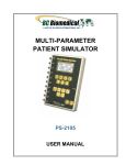
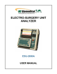
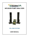
DEFIBRILLATOR
ANALYZERS
DA-2006
DA-2006P
W/ PACER
ANALYZER
USER MANUAL
BC BIOMEDICAL
DA-2006 SERIES
TABLE OF CONTENTS
WARNINGS, CAUTIONS, NOTICES ........................................................................... iii
DESCRIPTION .............................................................................................................
1
LAYOUT .......................................................................................................................
7
DEFIBRILLATOR ANALYZER ..................................................................................... 15
MAIN SCREEN.................................................................................................. 15
ECG WAVEFORMS SCREEN .......................................................................... 22
PLAYBACK LAST PULSE SCREEN ................................................................. 25
START CHARGE TIMER SCREEN .................................................................. 27
PRINT HEADER ................................................................................................ 29
SELF TEST WAVEFORM ................................................................................. 31
RUNNING A DEFIBRILLATION TEST .............................................................. 32
INTRODUCTION .................................................................................... 32
DEFIBRILLATION TEST ........................................................................ 34
CARDIOVERSION TEST ....................................................................... 37
CHARGE TIME TEST ............................................................................. 41
SHOCK ADVISORY ALGORITHM TEST ............................................... 43
TRANSCUTANEOUS PACEMAKER ANALYZER ....................................................... 45
PACE MAIN SCREEN ...................................................................................... 45
PACER MODE SETUP SCREEN ..................................................................... 51
SENSITIVITY TEST .......................................................................................... 53
REFRACTORY PERIOD TEST ......................................................................... 55
PRINT MENU SCREEN ................................................................................... 57
PLAYBACK LAST PULSE SCREEN ................................................................ 59
i
MESSAGES ................................................................................................................. 61
SYSTEM SETUP ......................................................................................................... 63
POWER UP SETTINGS .............................................................................................. 64
AUTO SEQUENCE FUNCTION................................................................................... 65
VIEW MODE .................................................................................................... 67
RUN MODE ....................................................................................................... 71
PROGRAMMING AUTO SEQUENCES ....................................................................... 80
MANUAL REVISIONS .................................................................................................. 91
LIMITED WARRANTY ................................................................................................. 91
SPECIFICATIONS ....................................................................................................... 92
NOTES ......................................................................................................................... 98
This User Manual covers the following units:
DA-2006
DA-2006P
ii
WARNING - USERS
The DA-2006 Series Analyzers are for use by
skilled technical personnel only.
WARNING - USE
The DA-2006 Series Analyzers are intended for
testing only and they should never be used in
diagnostics, treatment or any other capacity
where they would come in contact with a patient.
WARNING - MODIFICATIONS
The DA-2006 Series Analyzers are intended for
use within the published specifications. Any
application beyond these specifications or any
unauthorized user modifications may result in
hazards or improper operation.
WARNING - CONNECTIONS
All connections to patients must be removed
before connecting the DUT to the DA-2006 Series
Analyzers. A serious hazard may occur if the
patient is connected when testing with the
Analyzer. Do not connect any leads from the
patient directly to the Analyzer or DUT.
WARNING - LIQUIDS
Do not submerge or spill liquids on the DA-2006
Series Analyzers. Do not operate the Analyzer if
it may have been exposed to fluid.
CAUTION - CLEANING
Do not immerse. The Analyzer should be cleaned
by wiping gently with a damp, lint-free cloth.
A mild detergent can be used if desired.
iii
CAUTION - AC ADAPTOR
Unplug the AC Adaptor before
cleaning the surface of the DA-2006 Series
Analyzers.
CAUTION - SERVICE
The DA-2006 Series Analyzers are intended to be
serviced only by authorized service personnel.
Troubleshooting and service procedures should
only be performed by qualified technical
personnel.
CAUTION - ENVIRONMENT
Exposure to environmental conditions outside
the specifications can adversely affect the
performance and accuracy of the DA-2006 Series
Analyzer. If the Analyzer is outside the Operating
Specifications, allow it to acclimate to specified
conditions for at least 30 minutes before
attempting to operate it.
CAUTION - INSPECTION
The DA-2006 Series Analyzers should be
inspected before each use for wear and should
be serviced if any parts are in question.
iv
NOTICE – INDICATIONS FOR USE
The DA-2006 and DA-2006P Analyzers are
used to determine that defibrillators and
transcutaneous pacemakers are performing
within their performance specifications
through the measurement of energy output.
The DA-2006 tests defibrillators while the DA2006P additionally tests transcutaneous
pacemakers.
v
NOTICE – CE
The DA-2006 Series Analyzers bear the
mark
Based on the following testing standards:
ELECTROMAGNETIC COMPATIBILITY DIRECTIVE
EMC – Directive 89/336/EEC and 2004/108/EC as amended by
92/31/EEC, 93/68/EEC and Directive 91/263/EEC [ TTE/SES ]
EN 61326-1:1997 + A1:1998 + A2:2001 + A3:2003
“Electrical equipment for measurement, control and
laboratory use – EMC requirements”
This equipment has been type tested by an independent, accredited testing laboratory
and compliance was demonstrated to the above standard to the extent applicable.
EMISSIONS
Radiated and Line Conducted Emissions
EN 61000-3-2
EN 61000-3-3
Harmonic Current Emissions
Voltage Fluctuation and Flicker
IMMUNITY– CLASS C
EN 61000-4-2
EN 61000-4-3
EN 61000-4-4
EN 61000-4-5
EN 61000-4-6
EN 61000-4-11
Electrostatic Discharge
Radiated Electric Field Immunity
Electrical Fast Transients / Bursts
Surge Voltage
Conducted Disturbance
Voltage Dips and Short Interrupts
LOW VOLTAGE DIRECTIVE
EC – Directive 73/23/EC
EN 61010-1:2001
“Safety requirements for electrical equipment for measurement, control, and
laboratory use – General requirements”
This equipment has been type tested and compliance was demonstrated
to the above standard to the extent applicable.
vi
NOTICE – SYMBOLS
Symbol Description
Caution
(Consult Manual for Further Information)
Center Negative
Hazardous Voltage
Per European Council Directive 2002/95/EC,
do not dispose of this product as unsorted
municipal waste.
CAT I
IEC Measurement Category I – CAT I
equipment designed to protect against
transients in equipment on circuits not directly
connected to MAINS. Under no circumstances
should the terminals of the Analyzer be
connected to any MAINS voltage
vii
NOTICE – ABBREVIATIONS
AAMI
AHA
A, Amps
ANSI
ASCII
BPM
Association for the Advancement of Medical
Instrumentation
American Heart Association
Amperes
American National Standards Institute
American Standard Code for Information
Interchange
Beats Per Minute
C
Celsius
°
degree(s)
dt
Delta Time, Change in Time
DUT
E
Device Under Test
Energy
ECG
Electrocardiogram
Euro
European
Hz
IEC
J
kg
Lbs
Hertz
International Electrotechnical Commission
Joule(s)
kilogram(s)
pounds
µA
microampere(s)
µH
µV
microhenry
microvolt(s)
µsec
microsecond(s)
mA
milliampere(s)
mm
millimeter(s)
ms, mS, msec
mV
NEDA
millisecond(s)
millivolts
National Electronic Distributors Association
Ω
Ohm(s)
P
Power
ppm
pulse per minute
R
Resistance, ohms
Sec, S
USA
V
VDC
seconds
United States of America
Volt(s)
Volt(s) Direct Current
viii
NOTICE – DISCLAIMER
BC GROUP INTERNATIONAL, INC. WILL NOT BE RESPONSIBLE
FOR ANY INJURIES SUSTAINED DUE TO UNAUTHORIZED
EQUIPMENT MODIFICATIONS OR APPLICATION OF EQUIPMENT
OUTSIDE OF THE PUBLISHED INTENDED USE AND
SPECIFICATIONS.
NOTICE – DISCLAIMER
BC GROUP INTERNATIONAL, INC. RESERVES THE RIGHT TO
MAKE CHANGES TO ITS PRODUCTS OR SPECIFICATIONS AT
ANY TIME, WITHOUT NOTICE, IN ORDER TO IMPROVE THE
DESIGN OR PERFORMANCE AND TO SUPPLY THE BEST
POSSIBLE PRODUCT. THE INFORMATION IN THIS MANUAL HAS
BEEN CAREFULLY CHECKED AND IS BELIEVED TO BE
ACCURATE. HOWEVER, NO RESPONSIBILITY IS ASSUMED FOR
INACCURACIES.
NOTICE – CONTACT INFORMATION
BC BIOMEDICAL
BC GROUP INTERNATIONAL, INC.
3081 ELM POINT INDUSTRIAL DRIVE
ST. CHARLES, MO 63301
USA
1-800-242-8428
1-314-638-3800
www.bcgroupintl.com
[email protected]
DA-2006 Series User Manual
www.bcgroupintl.com
08/12
Copyright © 2012
Made in the USA
Rev 11
ix
This Page Intentionally Left Blank
x
BC BIOMEDICAL
DA-2006 SERIES
DEFIBRILLATOR ANALYZER
The Model DA-2006 Series is a microprocessor-based instrument family that is used in the
testing of defibrillators. They measure the energy output and provide information about the
defibrillation pulse. They are used on manual, semi-automatic and automatic defibrillators
with monophasic or biphasic outputs.
The DA-2006P model additionally provides a Transcutaneous Pacemaker analysis
function. It measures and displays pacer pulse information as well as performing
Refractory Period, Sensitivity and Immunity testing.
All models have a built in 50 Ω human body simulation load as well as 12 lead ECG with
arrhythmias and performance waveforms. Additionally, they have a Parallel Printer port, a
RS-232 serial communications port, oscilloscope output, high-level ECG output, as well as
provision for an AC adaptor.
The DA-2006 Series makes viewing and selecting the desired waveforms and test data
quick and intuitive, with all operational information being available on the 240 by 64 pixel
graphic display, allowing for easy maneuvering through parameters and scrolling through
available options.
The following are highlights of some of the main features:
DA-2006 (Basic Features):
SIMPLE TO OPERATE
GRAPHICS DISPLAY WITH SIMULTANEOUS DETAILED STATUS OF
PARAMETERS AND SCROLLING CONTROL OF OPTIONS
ON SCREEN VIEWING OF DEFIBRILLATOR AND PACEMAKER WAVEFORMS
DROP DOWN CHOICE SCREENS LIST ALL OPTIONS FOR PARAMETERS
MONOPHASIC AND BIPHASIC COMPATIBLE
5000 V, 1000 JOULE CAPACITY
HIGH AND LOW RANGES
CARDIOVERSION DELAY MEASUREMENT
CHARGE TIME MEASUREMENT
WAVEFORM STORAGE AND PLAYBACK
10 UNIVERSAL PATIENT LEAD CONNECTORS
POWERED BY 9 VOLT BATTERY OR OPTIONAL AC ADAPTOR
LOW BATTERY INDICATOR
DISPLAY BACKLIGHT
PARALLEL PORT FOR PRINTING
FULL REMOTE OPERATION VIA RS-232
FLASH PROGRAMMABLE FOR UPGRADES
1
AUTO SEQUENCE TESTING CAPABLE OF STORING 50 CUSTOM TEST
SEQUENCES
DA-2006P ADDS:
PACEMAKER OPTION
26 SELECTABLE INTERNAL LOADS
FULL PULSE ANALYSIS
DEMAND SENSITIVITY TEST
REFRACTORY PERIOD TESTS
50/60 Hz INTERFERENCE TEST SIGNALS
INPUT TERMINALS AND CIRCUITRY PROTECTED AGAINST
ACCIDENTAL DEFIBRILLATOR DISCHARGE INTO PACEMAKER
TEST TERMINALS
ENERGY OUTPUT MEASUREMENT GENERAL
The unit measures the energy in the output pulse of both monophasic and biphasic
defibrillators.
PULSE TYPE: Monophasic or Biphasic
LOAD RESISTANCE: 50 Ω ± 1%, non-inductive (<1 µH)
DISPLAY RESOLUTION: 0.1 Joules
MEASUREMENT TIME WINDOW: 100 ms
ABSOLUTE MAX PEAK VOLTAGE: 6000 Volts
CARDIOVERSION DELAY: 0 to 6000 ms
CARDIOVERSION RESOLUTION: 0.1 ms
ENERGY OUTPUT MEASUREMENT HIGH RANGE
The high range allows for a large pulse with high voltage and current.
VOLTAGE: ≤ 5000 Volts
MAX CURRENT: 100 Amps
MAX ENERGY: 1000 Joules
TRIGGER LEVEL: 100 Volts
PLAYBACK AMPLITUDE: 1 mV / 1000 V Lead I
TEST PULSE: 125 Joules ± 20%
2
ENERGY OUTPUT MEASUREMENT LOW RANGE
The low range allows greater resolution on smaller pulses.
VOLTAGE: < 1000 Volts
MAX CURRENT: 20 Amps
MAX ENERGY: 50 Joules
TRIGGER LEVEL: 20 Volts
PLAYBACK AMPLITUDE: 1 mV / 1000 V Lead I
TEST PULSE: 5 Joules ± 20%
ENERGY OUTPUT MEASUREMENT OTHER
OSCILLOSCOPE OUTPUT
HIGH MEASUREMENT RANGE: 1000:1 amplitude-attenuated
LOW MEASUREMENT RANGE: 200:1 amplitude-attenuated
WAVEFORM PLAYBACK
OUTPUT – LEAD 1 & PLATES
GRAPHICS SCREEN
200:1 Time Base Expansion
SYNC TIME MEASUREMENTS
TIMING WINDOW: Starts at peak of each R-wave
TEST WAVEFORMS: All waveform simulations available
CHARGE TIME MEASUREMENT
From 0.1 to 99.9 sec
ECG FUNCTIONS
The unit can produce a wide variety of ECG simulations. The user simply selects the
parameters that match the desired output.
RATE: 30, 40, 45, 60, 80, 90, 100, 120, 140, 160, 180, 200, 220, 240, 260, 280,
300 BPM
AMPLITUDE: 0.50, 1.0, 1.5, 2.0 mV (Lead II)
3
ECG PERFORMANCE FUNCTIONS
The unit can generate Sine, Square, Triangular, and Pulse waveforms with adjustable
amplitudes for performance testing.
SINE: 0.1, 0.2, 0.5, 5, 10, 40, 50, 60, 100 Hz
SQUARE: 0.125, 2 Hz
TRIANGLE: 2, 2.5 Hz
PULSE: 30, 60, 120 BPM; 60 ms WIDTH
AMPLITUDE: 0.5, 1.0, 1.5, 2.0 mV (Lead II)
ARRHYTHMIA FUNCTIONS
The unit can simulate 12 different arrhythmias.
VENTRICULAR FIBRILLATION
ATRIAL FIBRILLATION
SECOND DEGREE A-V BLOCK
RIGHT BUNDLE BRANCH BLOCK
PREMATURE ATRIAL CONTRACTION
EARLY PVC
STANDARD PVC
R ON T PVC
MULTIFOCAL PVC
BIGEMINY
RUN OF 5 PVC
VENTRICULAR TACHYCARDIA
SHOCK ADVISORY TESTS
The unit can simulate 8 different waveforms to test the shock algorithm of advanced
defibrillators:
ASYSTOLE
COARSE VENTRICULAR FIBRILLATION
FINE VENTRICULAR FIBRILLATION
MULTIFOCAL VENTRICULAR TACHYCARDIA @ 140 BPM
MULTIFOCAL VENTRICULAR TACHYCARDIA @ 160 BPM
POLYFOCAL VENTRICULAR TACHYCARDIA @ 140 BPM
POLYFOCAL VENTRICULAR TACHYCARDIA @ 160 BPM
SUPRAVENTRICULAR TACHYCARDIA @ 90 BPM
4
TRANSCUTANEOUS PACER ANALYZER (DA-2006P)
The unit can test external transcutaneous pacemakers. It has a wide variety of loads and
can measure the Pacer Pulse, Demand Sensitivity and Refractory Periods (Pacing and
Sensing):
LOAD:
RANGE: 50, 100, 150, 200, 300, 400, 500, 600, 700, 800, 900, 1000,
1100, 1200, 1300, 1400, 1500, 1600, 1700, 1800, 1900, 2000, 2100,
2200, 2300 Ω
PULSE:
PULSE CURRENT: 4 TO 300 mA (100 ohm load)
RATE: 30 TO 800 ppm
WIDTH: 0.6 to 80 ms
DEMAND SENSITIVITY:
WAVEFORMS:
SELECTIONS: SQUARE, TRIANGLE, HAVERSINE
WIDTH: 10, 25, 40, 100, 200 ms
ECG:
AMPLITUDE – OUT: 0 to 4 mV
PACER INPUT (50 TO 400 Ω):
AMPLITUDE – OUT: 0 to 10 mV / 50 Ω
RATE – IN: 30 to 100 ppm
PACER INPUT (500 TO 2300 Ω & OPEN):
AMPLITUDE – OUT: 0 to 100 mV
RATE – IN: 30 to 100 ppm
DEFIBRILLATOR PLATES:
AMPLITUDE – OUT: 0 to 10 mV
RATE – IN: 30 to 100 ppm
REFRACTORY PERIOD:
PACING: 20 to 500 ms
SENSING: 20 to 500 ms
50/60 HZ INTERFERENCE TEST SIGNAL:
ECG OUTPUT: 0, 0.4, 0.8, 1.2, 1.6, 2.0, 2.4, 2.8, 3.2, 3.6, 4.0 mV
PACER INPUT 50 OHM: 0, 1, 2, 3, 4, 5, 6, 7, 8, 9, 10 mV
PACER INPUT 100 OHM: 0, 2, 4, 6, 8, 10, 12, 14, 16, 18, 20 mV
PACER INPUT 150 OHM: 0, 3, 6, 9, 12, 15, 18, 21, 24, 27, 30 mV
PACER INPUT 200 OHM: 0, 4, 8, 12, 16, 20, 24, 28, 32, 36, 40 mV
PACER INPUT 300 OHM: 0, 6, 12, 18, 24, 30, 36, 42, 48, 54, 60 mV
PACER INPUT 400 OHM: 0, 8, 16, 24, 32, 40, 48, 56, 64, 72, 80 mV
PACER INPUT ≥ 500 OHM: 0, 10, 20, 30, 40, 50, 60, 70, 80, 90, 100
mV
DEFIBRILLATOR PLATES: 0, 1, 2, 3, 4, 5, 6, 7, 8, 9, 10 mV
INPUT CIRCUITRY PROTECTION
INPUT CIRCUITRY IS PROTECTED AGAINST DAMAGE IN THE
EVENT OF AN ACCIDENTAL DEFIBRILLATOR DISCHARGE INTO
THE PACEMAKER TEST INPUT TERMINALS
5
STANDARD ACCESSORIES:
BC20 - 00432
BC20 - 21103
(or)
BC20 - 21101
BC20 - 00427
INTERNAL PADDLE ADAPTERS (2 adapters)
AC ADAPTOR (USA Version)
AC ADAPTOR (Euro Version)
PLASTIC ELECTRODE PLATES (2 plates)
OPTIONAL ACCESSORIES:
BC20 - 30108
BC20 - 41341
BC20 - 41339
BC20 - 00420
BC20 - 00421
BC20 - 00423
BC20 - 00424
BC20 - 00425
BC20 - 00426
BC BIOMEDICAL SOFT-SIDED CARRYING CASE
RS-232 COMMUNICATIONS CABLE (DB-9M to DB-9F)
USB TO RS-232 ADAPTER (USB-A TO DB-9M)
PHYSIO-CONTROL DEFIB / PACE TEST CABLE
MARQUETTE DEFIB / PACE TEST CABLE
ZOLL DEFIB/PACE TEST CABLE
PHYSIO-CONTROL PACE ONLY TEST CABLE
ZOLL PACE ONLY TEST CABLE
HP / AGILENT / LAERDAL / AAMI
DEFIB / PACE TEST CABLE
6
LAYOUT
This section looks at the layout of a DA-2006 and gives descriptions of the elements that
are present.
LCD Graphical Display:
Shows Parameters for Test
Data and Waveforms
10 Universal
Patient Lead
Connectors:
RA R
LA
L
RL(-) N
LL
F
V1 C1
V2 C2
V3 C3
V4 C4
V5 C5
V6 C6
Range Key
for selecting
Defib input
range high or
low
Back Light Key
for turning on
and off the
backlight
5 Light Touch Keys
for Dynamic
functions:
These keys are
labeled in the
bottom portion of
the screen and
change function
based on operating
mode.
Large Defib Plates:
Fixed 50 ohm input
load for Defibrillator
testing
7
This section looks at the layout of a DA-2006P and gives descriptions of the elements that
are present.
10 Universal
Patient Lead
Connectors:
RA R
LA
L
RL(-) N
LL
F
V1 C1
V2 C2
V3 C3
V4 C4
V5 C5
V6 C6
LCD Graphical Display:
Shows Parameters for Test
Data and Waveforms
Range Key
for selecting
Defib input
range high or
low and
pace mode
Back Light Key
for turning on
and off the
backlight
Pacemaker
Input Jacks
Variable Load
(optional):
50-2300 ohms
5 Light Touch Keys
for Dynamic
functions:
These keys are
labeled in the
bottom portion of
the screen and
change function
based on operating
mode.
Large Defib Plates:
Fixed 50 ohm input
load for Defibrillator
testing and Pacer
Input
8
This section looks at the layout of the back and gives descriptions of the elements that are
present.
Oscilloscope
output
BNC connector
for easy
viewing of input
waveforms
Power Switch
AC Adaptor:
2.1 mm Jack
High Level
ECG output
RCA Jack
Serial Port
Female 9-Pin
D-Sub
Connector
NOTE
The DA-2006 and the DA-2006P offer the same
features, with the DA-2006P having the addition
of a Transcutaneous Pacemaker Analyzer
function (See Pacemaker Analyzer section
for more details).
9
Parallel Port
Female 25-Pin
D-Sub
Connector
General Operation
The unit is controlled by 7 light touch keys. They allow the user to move around within the
displayed parameters, select the desired options, choose a specific category and control
the setup for the unit. When a key is depressed there is an audio click when it is accepted,
or a razz tone if the key is invalid.
A large LCD graphics display with backlight provides the user with information about the
current status of the device configuration options, test results and more. The display
identifies the function of each key on a dynamic basis. As the operation mode changes,
the key functions change to suit the operating mode.
Range Key
The
key scrolls through the ranges of the DA-2006 Series analyzers. Depressing
the key will allow the user to select between High Defibrillator Range (1000J max), Low
Defibrillator Range (50J max) and, with the DA-2006P, Pacemaker Range. The default
mode on power up is High Defibrillator Range.
Backlight Key
The Graphic LCD display may be viewed with or without the backlight. Depressing any key
will activate the backlight. However, since the backlight will drain the battery if left on, it will
automatically shut off after a user programmable delay when running on battery power.
The
key is provided to toggle the backlight on or off at any time.
10
Function Keys
There are five
keys that are used to provide general operational control. The
functions of the keys vary depending on the current screen. The section of the screen
just above the key indicates its current meaning.
NOTE: Only functions that are available to the user will be visible at any given time.
Sample Function Key Labeling
ECG Waveforms
The microprocessor sends the waveforms to a Digital to Analog converter that generates
an accurate analog representation. The waveforms are then sent through a resistor
network, developing the appropriate signals on the output terminals.
11
Universal Patient Lead Connectors
The 10 Universal Patient Lead Connectors allow for 12 lead ECG simulations. AHA and
IEC color-coded labels are located on the face of the unit to aid in connecting the
corresponding U.S. and International Patient Leads.
AHA Label
IEC Label
Description
RA
R
Right Arm
LA
L
Left Arm
RL
N
Right Leg
(reference or ground)
LL
F
Left Leg
V1
V2
V3
V4
V5
V6
C1
C2
C3
C4
C5
C6
V Leads (V1-V6)
(U.S. and Canada)
also referred to as pericardial,
precordial or unipolar chest leads
Chest Leads (C1-C6)
(International)
12
High Level Output (+)
A high level ECG output signal (200x Amplitude Setting) is available on the RCA jack
located on the rear of the unit.
RS-232 Serial Port
A female 9-pin D-Sub connector is provided for the connection of the unit to a PC. This
link can be used for either remote interfacing or flash downloading of software upgrades.
Parallel Port
A female 25-pin D-Sub connector is provided for the connection of a printer via a
Centronics parallel interface.
Oscilloscope Output
A BNC connector is provided to connect an oscilloscope to the unit. This output provides
an attenuated version of the input signal.
13
Power Switch
A rocker switch is provided on the rear of the unit to turn the power on and off.
Battery
The unit utilizes two 9 Volt Alkaline Batteries in the bottom battery compartments. When
the unit detects a LOW BATTERY condition (10% Battery Life), a warning window will
appear once per minute to alert the user.
AC Adaptor
The unit has a 2.1 mm jack for powering the unit with an AC Adaptor.
Note: The AC Adaptor does not charge the batteries.
14
DEFIBRILLATOR ANALYZER
MAIN SCREEN
When the DA-2006 is first powered up, the Defibrillator Analyzer MAIN SCREEN will be
displayed. This screen shows the current CONFIGURATION, the TEST RESULTS and the
available FUNCTION KEYS. All defibrillator tests are run from the MAIN SCREEN. When
the unit detects an input of greater than 100 Volts on the Defibrillator Plates (20 Volts in
Low Range), it will automatically begin a test.
The default configuration is the High Range Defibrillator mode. This mode allows for a
waveform of up to 1000 Joules to be analyzed.
The following is a sample screen for this mode:
15
The
key may be used to toggle the unit to the Low Range Defibrillator mode. This
mode allows for waveforms up to 50 Joules to be analyzed. The Defibrillator Analyzer
works the same in both ranges. The lower range simply provides for a higher resolution for
pulses with smaller amplitudes.
The following is a sample screen for this mode:
NOTE: The
key will also put the DA-2006P into the Transcutaneous Pacemaker
Analyzer mode (See Pacemaker Analyzer section for more information).
16
CONFIGURATION
The CONFIGURATION section of the MAIN SCREEN displays the current setup of the
unit.
RANGE
The first line displays the range value for the pulse. It may be either 1000 Joules or 50
Joules max. This setting may be changed using the
key.
NOTE: This line also allows for the selection of the Pacer Analyzer that is an option
available in the DA-2006P model. The
key will toggle to Pacer to put the unit into
the Pacemaker Analyzer mode (See Pacemaker Analyzer section for more information).
STATUS
This line provides information about the current status of the analyzer.
ECG
This line displays the selection that is active on the ECG terminals. This setting may be
changed in the ECG WAVEFORMS screen.
AMP
This line displays the amplitude that has been selected for the ECG terminals. This setting
may be changed in the ECG WAVEFORMS screen.
17
TEST RESULTS
The TEST RESULTS section of the MAIN SCREEN displays the results of the last pulse.
It will continue to be displayed until the power is turned off, another test is run or the range
is changed.
NOTE: The unit automatically starts a test when it sees a voltage greater than 100 Volts
on the Defibrillator Plates (20 Volts in Low Range).
NOTE: Test results are immediately sent to the printer port as soon as the data is
available.
ENERGY
This line displays the total energy of the last pulse.
PEAK V
This line displays the peak voltage of the last pulse.
PEAK I
This line displays the peak current of the last pulse.
18
DELAY
This line normally displays the delay from the peak of the R wave until the start of the Defib
Energy pulse. The line is replaced by the CHARGE TIME if this test has been run (see
START CHARGE TIMER SCREEN for more information).
CHG TIME
This line displays if the Charge Timer has been run. It shows the time required to charge
the Device Under Test (DUT). This test is started with the
19
key.
FUNCTION KEYS
The FUNCTION KEYS section of the MAIN SCREEN displays the current functions of the
keys found below the display. These keys allow for navigation to supporting screens and
initiation of specific features.
Primary Function Keys
Secondary Function Keys
ECG WAVEFORMS
This key enters the ECG WAVEFORMS screen where all ECG parameters are set.
PLAYBACK LAST PULSE
This key enters the PLAYBACK LAST PULSE screen where a graphical representation of
the last pulse may be viewed and sent out.
START CHARGE TIMER
This key brings up the CHARGE TIMER screen and starts the pre-warn timer. It is used to
test the charge time for the defibrillator.
PRINT HEADER
This key sends the Report Header to the printer.
MORE KEYS
These keys toggle between the Primary and Secondary Function Keys.
20
AUTO SEQUENCES
This key brings up the AUTO SEQUENCE MENU, which is used to view or run the Auto
Sequences stored in the unit.
SELF TEST WAVEFORM
This key sends an internal test pulse to the unit, allowing for the display of the results to
give an indication that the system is working properly.
DA-2006 SETUP
This key brings up the SYSTEM CONFIGURATION SCREEN, which allows for adjusting
the various system configuration parameters.
21
ECG WAVEFORMS SCREEN
The DA-2006 ECG output can be connected in 3, 5 or 12 lead configurations. Pressing the
key from the MAIN SCREEN will allow the user to configure the waveform
that is used for the ECG output.
The following is a sample of the ECG waveform configuration screen:
ECG GROUP
Disabled
NSR
AED
Arrhythmias
Performance
WAVEFORM
None
30,40,45,60,80,90,
100,120,140,160,
180,200,220,240,
260,280,300 BPM
Asystole
Coarse Vfib
Fine Vfib
Multifocal Vtach 140
Multifocal Vtach 160
Polyfocal Vtach 140
Polyfocal Vtach 160
SupraVent Tach 90
Vfib
Afib
Second Deg Block
RBBB
PAC
PVC Early
PVC STD
PVC R on T
MF PVC
Bigeminy
Run of 5 PVC
Vtach
0.125, 2 Hz Square
2, 2.5 Hz Triangle
0.1,0.2,0.5,5,10,40,5
0,60,100 Hz Sine
30, 60, 120 BPM
Pulse
AMPLITUDE
Lead I 0.35 mV
Lead I 0.70 mV
Lead I 1.05 mV
Lead I 1.40 mV
22
Lead II 0.5 mV
Lead II 1.0 mV
Lead II 1.5 mV
Lead II 2.0 mV
The ECG Group, Waveform and Amplitude can be selected using
the parameter and using
to highlight
to open a drop down menu of all the options for the
highlighted parameter.
Use
new setting.
to scroll to the desired option. Then
The
key can be used to return to the ECG waveform
configuration screen without making a new selection.
The
is used to accept the
key is used to return to the MAIN SCREEN.
23
The following is a brief description of how the DA-2006 simulates the available arrhythmias:
Abbreviation
Arrhythmia
Description
Vent Fib –
Fine
Ventricular Fibrillation
Atrial Fib
Atrial Fibrillation
2nd Deg Heart
Block
Second Degree Heart Block
Rt Bundle
Branch Block
Right Bundle Branch Block
PAC
Premature Atrial Contraction
PVC Early
Early Type 1
Premature Ventricular Contraction
PVC Std
Standard Type 1
Premature Ventricular Contraction
PVC R on T
R on T Type 1
Premature Ventricular Contraction
Multifocal
PVCS
Multifocal
Premature Ventricular Contraction
Bigeminy
Bigeminal Rhythm
Run of 5
PVCs
Run of 5 Premature Ventricular
Contractions
Vent Tach
Ventricular Tachycardia
24
Irregular waveform with no real
P-wave or clear R-R interval and a low
signal level
(Continuous)
Absence of P-wave, irregular P-R
interval rate and a high level signal
(Continuous)
80 BPM with increasing
P-R interval for four beats
(160, 220, 400, 470 ms)
followed by a P wave without a QRS
(Continuous)
80 BPM with Normal P-wave and P-R
interval but wider QRS complexes
(Continuous)
NSR of 80 BPM with Periodic
Abnormal 25% early P waves
(PAC, 7 NSR)
(Continuous)
NSR of 80 BPM with periodic left focus
premature ventricular beats with 33%
premature timing
(PVC Type 1, 9 NSR)
(Continuous)
NSR of 80 BPM with periodic left focus
premature ventricular beats with 20%
premature timing
(PVC Type 1, 9 NSR)
(Continuous)
NSR of 80 BPM with periodic left focus
premature ventricular beats with 65%
premature timing, placing R on the
previous T
(PVC Type 1, 9 NSR)
(Continuous)
NSR of 80 BPM with Type 1 and Type
2 PVCs (PVC Type 1, 2 NSR, PVC
Type 2, 2 NSR)
(Continuous)
NSR of 80 BPM with every other beat
a Type 1 PVC
(Continuous)
NSR of 80 BPM with periodic group of
5 Type 1 PVCs
(5 PVC Type 1, 36 NSR)
(Continuous)
160 BPM, No P-wave,
Beats similar to Type 1 PVC
(Continuous)
PLAYBACK LAST PULSE SCREEN
The DA-2006 can display a graphical representation of the last pulse. This screen may be
accessed by pressing the
key from the Defibrillator Analyzer MAIN
SCREEN. The playback allows the user to view the Defibrillator pulse in a time-expanded
form. Samples are stored internally at 0.1 ms intervals. The PLAYBACK LAST PULSE
SCREEN shows these samples expanded by a time factor of 200.
In playback mode, the samples are shown on the display and sent out the ECG leads,
Defibrillator Plates and the High Level output. The following is a sample of the waveform
that is shown in the display:
The scale shown on the screen is automatically adjusted to provide the maximum
resolution available.
The
key can be used to pause the screen at any point while a pulse is being
played back. This key replaces the
The
key when a pulse is being played back.
key can be used to play (continue) the waveform if it has been paused.
This key replaces the
key.
25
The
key starts a playback of only the first 20 ms of the waveform.
The
key starts a playback of the entire 100 ms of the waveform.
At any time, the
key or
key can be depressed to return to the
MAIN SCREEN.
26
START CHARGE TIMER SCREEN
A special timer has been incorporated into the DA-2006 to analyze the charging circuit of
the Device Under Test (DUT). The START CHARGE TIMER SCREEN can be accessed
by pressing the
key from the MAIN SCREEN. To synchronize the charge
timer with the defibrillator charge time, a Pre-Warning Countdown period is started. When
the timer reaches zero, the defibrillator charge should be initiated. The following is an
example of the countdown timer:
When the timer reaches zero, a beep will sound and the charge timer
will begin counting up. The following is an example of the count up timer:
27
The DUT should be discharged as soon as it becomes charged. When the DUT is
discharged, the timer will automatically stop. The display will show the results of the
Defibrillator pulse analysis as well as the time required to charge the DUT:
Charge Timer
Results
At any time, the
key can be depressed to end the timer and return to the
MAIN SCREEN.
28
PRINT HEADER
The DA-2006 provides a header for recording test data as well as the results of each pulse
that is discharged into the unit. Test results are immediately sent to the printer port as
soon as the data is available. The header is sent by pressing the
key from
the MAIN SCREEN.
The status line of the configuration section will indicate that the header has been sent to
the printer.
29
The following is the print header and sample data that are used for the Defibrillator
Analyzer mode.
NOTE: Printing the header also resets the test number printed on the data sheet.
NOTE: In the test results, the user must manually write the power setting of the DUT.
30
SELF TEST WAVEFORM
The DA-2006 has built in test waveforms that will give an indication that the system is
working properly. The Self Test Waveform may be sent by pressing the
key
from the MAIN SCREEN.
After the waveform has been sent, the results will be reflected in the test results section of
the MAIN SCREEN and the PLAYBACK LAST PULSE SCREEN. The Self Test Waveform
is not calibrated, but will provide a waveform that is approximately 125 Joules when
configured for the High Range and 5 Joules when configured for the Low Range.
The following is an example of the MAIN SCREEN with the results of the Self Test
Waveform:
The following is an example of the PLAYBACK LAST PULSE SCREEN, showing a
graphical representation of the Self Test Waveform:
31
RUNNING A DEFIBRILLATOR TEST
WARNING - CONNECTIONS
All connections to patients must be removed
before connecting the DUT to the DA-2006 Series
Analyzers. A serious hazard may occur if the
patient is connected when testing with the
Analyzer. Do not connect any leads from the
patient directly to the Analyzer or DUT.
INTRODUCTION
The DA-2006 will analyze the pulse output of a monophasic or biphasic defibrillator. The
primary measure of the output is the Energy that it contains. Other information deals with
the maximum voltage and current as well as the pulse timing with respect to the R-wave.
The human body has characteristic impedance that may vary, but 50 ohms is used for
comparative defibrillator testing. The DA-2006 has a large internal 50 ohm noninductive, high-power resistor to simulate a human body. It is sized to safely and
reliably accept repeated pulses at the maximum energy levels.
32
The energy contained in a pulse is determined mathematically based on the fact that
the energy is defined as the integral of the power curve. The following formulas
describe the basic computation:
Power: P = V2 / R
Energy: E = P dt
= V2 / R dt
= V2 dt / R
This computation is implemented digitally by taking timed samples of the voltage every
100 µsec for 100 msec (1000 readings). Each value is then squared and divided by the
resistance (50 ohms). The sum of these 1000 values times 10 is then the Energy in
Joules (Watt Seconds) contained in the pulse.
33
DEFIBRILLATION TEST
The setup for a Defibrillation Test is dependent on the physical hardware involved. For
the sake of this example we will assume a standard defibrillator with 5 lead ECG.
NOTICE – PERFORMING TESTS
REFER TO DUT MANUFACTURER’S SERVICE MANUAL FOR
TEST PROCEDURES AND MEASUREMENT LIMITS .
(1) Connect ECG leads to the corresponding universal connector on the DA-2006.
The connectors are marked with both the AHA and International color codes.
(2) Turn on the DA-2006.
(3) The unit will come up in the “High Range Defibrillator” mode. This range is used
for normal adult testing.
NOTE: If it is desirable to run a test at 50 Joules or less with a peak
voltage of 1000 Volts or less, the unit may be changed to the “Low Range
Defibrillator” mode using the
key.
(4) Select “Ventricular Fibrillation” from the ECG WAVEFORM SCREEN with an
amplitude of 1 mV. This is necessary for most automatic defibrillators.
(5) Place the Defibrillator Paddles on the DA-2006 contact plates. The APEX is on
34
the right and the STERNUM is on the left.
NOTE: Reversing the paddles will not cause any damage to the unit or
error in the energy reading. However, it will cause the polarity of the
oscilloscope output and the playback waveform to be inverted.
(6) Holding the paddles firmly in place, charge the Defibrillator and discharge it into
the DA-2006.
WARNING
Observe all precautions noted by the Defibrillator
Manufacturer when using the Defibrillator.
(7) The DA-2006 will automatically sense the voltage rise across the internal 50
ohm load and begin taking readings. After the sampling is done (100 ms) the
unit will compute and display the results.
a. The power pulse is available at the oscilloscope output in real time at
200:1 signal attenuation when in low range and 1000:1 signal attenuation
when in high range.
b. After the computation, the pulse is automatically played back at a 200:1
time base expansion (200 times slower) on both the ECG leads and the
Paddle plates. The signal level is 1 mV per 1000 Volts on Lead 1.
c. At the same time, the test results are sent to the printer.
35
(8) The Status line will change to indicate the various steps as they are being done.
(9) At the end of the process the results are continuously displayed in the Test
Results section of the MAIN SCREEN. They will remain there until another test
is performed, the range is changed or the power is turned off.
(10) The user may repeat the playback of the waveform at any time by changing to
the PLAYBACK LAST PULSE SCREEN using the
key. In this
screen the pulse may be viewed in 20 msec segments and paused for review.
NOTE: The pulse is sent to the ECG and Paddle outputs at the same time
it is being displayed on the screen.
36
CARDIOVERSION TEST
A Cardioversion Test is simply an energy test with special attention being given to the
timing. The DA-2006 continuously monitors for the R-wave timing and displays, if
possible, the delay between the R-wave and the pulse. In Cardioversion testing, the
Defibrillator is set to deliver a pulse based on a specific delay after the R-wave.
WARNING
This section is provided as a guide to familiarize
the user with the DA-2006 Series. It is not
intended to provide the necessary test sequence
for every Defibrillator. The user must consult the
manufacturer’s manual for each DUT to
determine the correct test procedure to follow.
(1) Connect ECG leads to the corresponding universal connector on the DA-2006.
The connectors are marked with both the AHA and International color codes.
(2) Turn on the DA-2006.
(3) The unit will come up in the “High Range Defibrillator” mode. This range is used
for normal adult testing.
NOTE: If it is desirable to run a test at 50 Joules or less with a peak
voltage of 1000 Volts or less, the unit may be changed to the “Low Range
Defibrillator” mode using the
key.
37
(4) Select the desired ECG Waveform and Amplitude to be tested from the choices
on the ECG WAVEFORM SCREEN.
NOTE: The selected waveform must contain a QRS complex.
(5) Set the Defibrillator to Synchronized Cardioversion mode.
(6) Place the Defibrillator Paddles on the DA-2006 contact plates. The APEX is on
the right and the STERNUM is on the left.
NOTE: Reversing the paddles will not cause any damage to the unit or
error in the energy reading. However, it will cause the polarity of the
oscilloscope output and the playback waveform to be inverted.
(7) Holding the paddles firmly in place, charge the Defibrillator and discharge it into
the DA-2006.
WARNING
Observe all precautions noted by the Defibrillator
Manufacturer when using the Defibrillator.
38
(8) The DA-2006 will automatically sense the voltage rise across the internal 50
ohm load and begin taking readings. After the sampling is done (100 ms) the
unit will compute and display the results.
a. The power pulse is available at the oscilloscope output in real time at
200:1 signal attenuation when in low range and 1000:1 signal attenuation
when in high range.
b. After the computation, the pulse is automatically played back at a 200:1
time base expansion (200 times slower) on both the ECG leads and the
Paddle plates. The signal level is 1 mV per 1000 Volts on Lead 1.
c. At the same time, the test results are sent to the printer.
(9) The Status line will change to indicate the various steps as they are being done.
(10) At the end of the process the results are continuously displayed in the Test
Results section of the MAIN SCREEN. They will remain there until another test
is performed, the range is changed or the power is turned off.
NOTE: Special note should be made of the “Delay: xxx msec” line in the
results. This will show the delay between the peak of the R-wave and the
start of the Pulse.
39
The user may repeat the playback of the waveform at any time by changing to the
PLAYBACK LAST PULSE SCREEN using the
key. In this screen the
pulse may be viewed in 20 msec segments and paused for review.
NOTE: The pulse is sent to the ECG and Paddle outputs at the same time
it is being displayed on the screen.
40
CHARGE TIME TEST
The charging time of a Defibrillator is nothing more than a measurement of the time
required for the Defibrillator to charge. It is used to test the battery, charging circuitry
and capacitor. The DA-2006 provides a simple way to start and stop the timer. It also
records the results.
WARNING
This section is provided as a guide to familiarize
the user with the DA-2006 Series. It is not
intended to provide the necessary test sequence
for every Defibrillator. The user must consult the
manufacturer’s manual for each DUT to
determine the correct test procedure to follow.
(1) Turn on the DA-2006.
(2) The unit will come up in the “High Range Defibrillator” mode. This range is used
for normal adult testing.
(3) Set the Defibrillator to its maximum power setting.
(4) Depress the
key.
41
(5) While the Pre-Warning Countdown is running, place the Defibrillator Paddles on
the DA-2006 contact plates. The APEX is on the right and the STERNUM is on
the left.
NOTE: Reversing the paddles will not cause any mage to the unit or error
in the energy reading. However, it will cause the polarity of the
oscilloscope output and the playback waveform to be inverted.
(6) Holding the paddles firmly in place, wait until the Pre-Warning Countdown
equals zero and then immediately start charging the Defibrillator.
(7) As soon as the DUT is fully charged, discharge it into the DA-2006.
WARNING
Observe all precautions noted by the Defibrillator
Manufacturer when using the Defibrillator.
(8) At the end of the process the results are continuously displayed in the Test
Results section of the MAIN SCREEN. They will remain there until another test
is performed, the range is changed or the power is turned off.
NOTE: The last line in the Test Results section of the screen will show
“Chg Time: xxx.x sec”
42
SHOCK ADVISORY
ALGORITHM TEST
The Shock Advisory Algorithm Test works with the analysis and prompting functions on
automatic and semiautomatic Defibrillators. These circuits look at ECG waveforms and
prompt the user to “Shock” or “No Shock” based on national and international
guidelines. The following table outlines these guidelines:
SHOCK ADVISORY ALGORITHM TEST
ECG SIGNALS
ACTION
Asystole
No Shock
Supra Ventricular Tachycardia @ 90 BPM
No Shock
Polyfocal Ventricular Tachycardia @ 140 BPM
No Shock
Multifocal Ventricular Tachycardia @ 140 BPM
No Shock
Coarse Ventricular Fibrillation
Shock
Fine Ventricular Fibrillation
Shock
Polyfocal Ventricular Tachycardia @ 160 BPM
Shock
Multifocal Ventricular Tachycardia @ 160 BPM
Shock
WARNING
This section is provided as a guide to familiarize
the user with the DA-2006 Series. It is not
intended to provide the necessary test sequence
for every Defibrillator. The user must consult the
manufacturer’s manual for each DUT to
determine the correct test procedure to follow.
43
(1) Connect ECG leads to the corresponding universal connector on the DA-2006.
The connectors are marked with both the AHA and International color codes.
(2) Turn on the DA-2006.
(3) The unit will come up in the “High Range Defibrillator” mode. This range is used
for normal adult testing.
(4) Select the desired AED Waveform and Amplitude to be tested from the choices
on the ECG WAVEFORM SCREEN.
(5) Set the Defibrillator to analyze the ECG waveform in the automatic or
semiautomatic mode.
(6) Observe and record the response of the Defibrillator to the various waveforms.
44
TRANSCUTANEOUS PACEMAKER ANALYZER
The DA-2006P can analyze pacemaker pulses as well as determine Refractory periods
and Sensitivity levels of on-demand pacemakers. For maximum versatility, the DA-2006P
has 26 internally selectable pacemaker loads ranging from 50 ohms to 2300 ohms. The
DA-2006P can also test the noise immunity of the DUT by generating a 50 or 60 Hz noise
waveform with amplitude up to 100 mV. For sensitivity testing, the DA-2006P can output
a Square, Triangle or Haversine waveform with widths ranging from 10ms to 200ms. The
input circuitry of the DA-2006P is protected against damage in the case of an accidental
defibrillator discharge into the Pacemaker Input terminals.
The
key is used to change to the Pacemaker Analyzer mode.
PACE MAIN SCREEN
The Pacemaker Analyzer MAIN SCREEN shows the current CONFIGURATION, the TEST
RESULTS and the available FUNCTION KEYS.
The following is a sample of the PACE MAIN SCREEN:
NOTE: The Test Results section of the PACE MAIN SCREEN contains eight lines of data
that can be toggled to view the first 4 lines or the second 4 lines (See TEST RESULTS
section of manual for more information).
45
CONFIGURATION
The CONFIGURATION section of the PACE MAIN SCREEN displays the current setup of
the unit.
LOAD
This line displays the selected load. This setting may be changed in the PACE MODE
SETUP screen. The load choice determines what impedance is used at the pacemaker
input as well as whether the unit uses the Pacer Input Terminals or the Defibrillator Plate
Input Terminals.
NOISE
This line displays the selected noise output. This setting may be changed in the PACE
MODE SETUP screen.
WAVE
This line displays the selected output waveform. This setting may be changed in the
PACE MODE SETUP screen. The selected waveform is the output to the pacer on the
ECG Terminals, Pacer Terminals and Defibrillator Plate Terminals.
46
TEST RESULTS
The TEST RESULTS section of the PACE MAIN SCREEN displays the results of the last
test. It will continue to be displayed until the power is turned off or another test is run.
The Test Results section of the PACE MAIN SCREEN contains eight lines of data that can
be toggled to view the first 4 lines or the second 4 lines by pressing the
key.
RATE
This line displays the rate of the pacemaker pulse that is present at the selected load.
WIDTH
This line displays the width of the pacemaker pulse that is present at the selected load.
AMP
This line displays the current of the pacemaker pulse that is present at the selected load.
47
ENERGY
This line displays the energy of the pacemaker pulse that is present at the selected load.
SENS PADS
This line displays the sensitivity at the pads for the selected waveform during the last
Sensitivity Test.
SENS ECG
This line displays the sensitivity at the ECG leads for the selected waveform during the last
Sensitivity Test.
PACED RP
This line displays the paced refractory period detected at the selected load during the last
Refractory Period Test.
SENSED RP
This line displays the sensed refractory period detected at the selected load during the last
Refractory Period Test.
48
FUNCTION KEYS
The FUNCTION KEYS section of the PACE MAIN SCREEN displays the current functions
of the keys found below the display. These keys allow for navigation to supporting screens
and initiation of specific features.
Primary Function Keys
Secondary Function Keys
PACE MODE SETUP
This key enters the PACE MODE SETUP SCREEN where all pace parameters are chosen.
SENSITIVITY TEST
This key activates a Sensitivity Test.
REFRACTORY PERIOD TEST
This key activates a Refractory Period Test.
TOGGLE TEST RESULTS
This key toggles the test result section to view the first 4 lines or the second 4 lines of data.
MORE KEYS
These keys toggle between the Primary and Secondary Function Keys.
PRINT MENU
This key enters the PRINT SCREEN that allows the printing of the header or the test data.
49
PLAYBACK LAST PULSE
This key enters the PLAYBACK LAST PULSE screen where a graphical representation of
the last pulse may be viewed and sent out.
AUTO SEQUENCES
This key brings up the AUTO SEQUENCE MENU, which is used to view or run the Auto
Sequences stored in the unit.
DA-2006 SETUP
This key brings up the SYSTEM CONFIGURATION SCREEN, which allows for adjusting
the various system configuration parameters.
50
PACER MODE SETUP SCREEN
The DA-2006P can be configured to run a large number of tests under various load
conditions. This screen is used to configure the unit for these tests. The pacemaker
configuration screen is accessed by pressing the
key from the PACE MAIN
SCREEN. In this screen, the user can select the desired Load, the output Noise waveform,
the Sensitivity Test waveform, and the Pacemaker Pulse Filter.
The following is a sample of the Pacemaker configuration screen:
LOAD
Defib Plates Input (50 )
50 ohm
100 ohm
150 ohm
200 ohm
200 ohm
300 ohm
400 ohm
500 ohm
600 ohm
700 ohm
800 ohm
900 ohm
1000 ohm
1100 ohm
1200 ohm
1300 ohm
1400 ohm
1500 ohm
1600 ohm
1700 ohm
1800 ohm
1900 ohm
2000 ohm
2100 ohm
2200 ohm
2300 ohm
Open
NOISE
WAVEFORM
10 mV 50 Hz
9 mV 50 Hz
8 mV 50 Hz
7 mV 50 Hz
6 mV 50 Hz
5 mV 50 Hz
4 mV 50 Hz
3 mV 50 Hz
2 mV 50 Hz
1 mV 50 Hz
NONE
1 mV 60 Hz
2 mV 60 Hz
3 mV 60 Hz
4 mV 60 Hz
5 mV 60 Hz
6 mV 60 Hz
7 mV 60 Hz
8 mV 60 Hz
9 mV 60 Hz
10 mV 60 Hz
10 ms Square
25 ms Square
40 ms Square
100 ms Square
200 ms Square
10 ms Triangle
25 ms Triangle
40 ms Triangle
100 ms Triangle
200 ms Triangle
10 ms SSQ
25 ms SSQ
40 ms SSQ
100 ms SSQ
200 ms SSQ
51
PULSE FILTER
0.0 – 2.0 ms
These settings can be selected using
and using
to highlight the parameter
to open a drop down menu of all the options for the highlighted
parameter.
Use
to scroll to the desired option. Then
new setting. The
is used to accept the
key can be used to return to the Pacemaker configuration
screen without making a new selection.
The
key is used to return to the PACE MAIN SCREEN.
PACEMAKER PULSE FILTER - This filter eliminates noise pulses from being detected as
pacemaker pulses. Any pulses that have a width less than the Pacemaker Pulse Filter
setting will be ignored. When set to 0.0, the filter is disabled. When the filter is ON, an
indicator will show “FILTER ON” in the main pacemaker screen.
52
SENSITIVITY TEST
The Sensitivity Test is used to determine the smallest waveform that the pacemaker can
detect. For this test, the selected waveform is generated outside of the refractory period of
the pacemaker. The DA-2006P uses a successive approximation approach to determine
the smallest output waveform that can be detected by the pacemaker. The Sensitivity Test
may be initiated by pressing the
key from the PACE MAIN SCREEN.
WARNING
This section is provided as a guide to familiarize
the user with the DA-2006P. It is not intended to
provide the necessary test sequence for every
Pacemaker. The user must consult the
manufacturer’s manual for each DUT to
determine the correct test procedure to follow.
While this test is running, the following display will show the progress of the test:
At any time, the
key can be depressed to stop the test and return to the
PACE MAIN SCREEN.
53
At the end of the test, the display will show the pacemaker amplitude sensitivity at the
Pacer Terminals and the ECG Terminals.
54
REFRACTORY PERIOD TEST
For on-demand pacemakers, the pacemaker should ignore any ECG activity after a pacer
pulse for a specific period of time. This time period is known as the Refractory Period.
The Paced Refractory Period is the time after the pacemaker pulse that ECG activity is
ignored. If an ECG pulse is present inside the refractory period, it is ignored. If an ECG
pulse is detected outside of the refractory period, the pacemaker will re-synchronize to the
sensed ECG pulse. For each sensed ECG pulse, there is a second refractory period. This
is known as the Sensed Refractory Period. It is the period of time after the sensed ECG
pulse that ECG activity is ignored. The Refractory Period Test may be initiated by pressing
the
key from the PACE MAIN SCREEN.
WARNING
This section is provided as a guide to familiarize
the user with the DA-2006P. It is not intended to
provide the necessary test sequence for every
Pacemaker. The user must consult the
manufacturer’s manual for each DUT to
determine the correct test procedure to follow.
While the Refractory Period test is running, the display will indicate the progress of the test:
NOTE: It is important that the pulse rate does not change for the duration of the Refractory
Test.
55
At any time, the
key can be depressed to stop the test and return to the
PACE MAIN SCREEN.
When the test is completed, the display will update with the Paced Refractory Period and
Sensed Refractory Period in the Test Results.
56
PRINT MENU SCREEN
The DA-2006P allows the user to print the latest Pacemaker Analysis data or a header.
The PRINT MENU SCREEN is accessed by pressing the
key from the
PACE MAIN SCREEN.
The following is an example of the print menu screen:
The header is sent by pressing the
key.
The test data is sent by pressing the
The
key.
key can be depressed to return to the PACE MAIN SCREEN.
57
The following is the print header and sample data that are used for the Pacemaker
Analyzer mode:
NOTE: Since Pacemaker pulses are normally continuous, the test data must be printed
manually via the Print Menu.
NOTE: Printing the header also resets the test number printed on the data sheet.
58
PLAYBACK LAST PULSE SCREEN
The DA-2006P can display a graphical representation of the last pulse. This screen may
be accessed by pressing the
key from the PACE MAIN SCREEN. The
playback allows the user to view the Pacemaker pulse in a time-expanded form. Samples
are stored internally at 0.1 ms intervals. The PLAYBACK LAST PULSE SCREEN shows
these samples expanded by a time factor of 200.
In playback mode, the samples are shown on the display and sent out the ECG leads,
Defibrillator Plates, and the High Level output. The following is a sample of the waveform
that is shown in the display:
The scale shown on the screen is automatically adjusted to provide the maximum
resolution available.
The
key can be used to pause the screen at any point while a pulse is being
played back. This key replaces the
The
key when a pulse is being played back.
key can be used to play (continue) the waveform if it has been paused.
This key replaces the
key.
59
The
key starts a playback of only the first 20 ms of the waveform.
The
key starts a playback of the entire 100 ms of the waveform.
At any time, the
key or
key can be depressed to return to the
MAIN SCREEN.
60
MESSAGES
INPUT OVERLOAD
The “Warning Input Overload Check Range” message can display during Defibrillator
testing. The range should be checked to see if it should be changed to High Range for the
current Joule setting.
NO PULSE (DA-2006P Only)
The “Test Cancelled No Pulse for 3 seconds” message can display during Refractory or
Sensitivity Pacer testing. The settings should be checked and the test rerun.
61
SENSITIVITY TOO HIGH (DA-2006P Only)
The “Test Cancelled DUT Sensitivity too high” message can display during Pacer testing.
This happens when the Pacemaker does not detect the pulse generated by the DA-2006P.
It could be that it is connected improperly or set to Async mode. This can occur during
either the Sensitivity or Refractory test modes.
LOW BATTERY
This message indicates that the batteries are low and should be replaced.
EXITING AUTO SEQUENCE TESTING
The “Exit Auto Sequence Test All Data Will be Lost!” message will display in the Auto
Sequencing Mode when
is pushed. If the data is needed, it should be
printed prior to exiting.
62
SYSTEM SETUP
The SYSTEM SETUP SCREEN allows for the configuration of the system settings. The
settings can be selected using
to highlight the parameter and using
to allow the editing of the parameter. The
the setting, then
keys are used to edit
is used to accept the new setting. The
key can
be used to return to the configuration screen without making a new selection.
The
key is used to return to the MAIN SCREEN.
The following is a brief description of the parameters and the available range of settings:
Parameter
Backlight-Timed
Autosequence
Timer
Battery Life
Power up with
Software
Description
Off – Always off
1-20 sec – The elapsed time after which the
backlight will automatically turn off.
Always On – The backlight will be manually
controlled by backlight key)
Sets the delay between Auto Sequence
tests when the test passes.
Displays current life of the batteries. At 5%,
a warning screen will appear. At 10%, the
unit will power down automatically.
Selects the values that will be used when
the unit is first turned on. It is also used to
Set the Custom Defaults, if used. (See
Power Up Settings).
Displays current software program.
63
Range
Off, 1-20 sec,
Always On
1-20 sec
5-100%
(Read Only)
Default/Last/
Custom/
Set Custom
Defaults
(Read Only)
POWER UP SETTINGS
The DA-2006 Series allows the user to tailor the settings that the unit will have on Power
Up. The “Power Up With” parameter in the System Setup Menu allows for the selection of
either Default or Custom selections.
DEFAULT
If this option is selected the following settings will be used every time the unit is turned on.
Range – Defib, High Range mode
ECG – Output Disabled
Pacemaker Load – 100 ohm
Pacemaker Noise Waveform- None
Pacemaker Output Waveform – 40 ms Square wave.
CUSTOM
If this option is selected, the user may save a unique set of default parameters and the unit
will recall them every time the power is turned on.
SET CURRENT AS CUSTOM
The user simply configures the unit to the desired default conditions, selects this option
and presses
. The current configuration is then saved as the Custom Power
up values.
64
AUTO SEQUENCE FUNCTION
The DA-2006 Series allows the user run up to 50 pre-programmed sequences of tests
(Auto Sequences). The tests are configured with an easy to use PC program. Each test
can be configured to test Defibrillator, Transcutaneous Pacemaker or both.
(For
programming Auto Sequences, see the Auto Sequence Programming section). Once
configured, the tests are then downloaded to the DA-2006 unit through the RS232 serial
interface.
The AUTO SEQUENCE SCREEN is accessed using the
key.
AUTO SEQUENCES
In this menu, the
keys are used to select the
desired test. The
key can be used to enter the
VIEW MODE which will allow the user to view the programed test options of the selected test. The
key will
run the selected test and enter the RUN MODE which will
step the technician through the programmed test as well as
LifePak 4
LifePak 5
LifePak 6
LifePak 6S
LifePak 8P
LifePak 9P
LifePak 9PM
LifePak 10
LifePak 10P
LifePak 10PM
HP 78660A
HP XLPM
Nihon Kohden 7000
Laerdal HS 2000
Marquette 1500PM
Zoll PD 2000
Zoll M-Series DSW
Zoll AED Plus
Blank Tests 20-50
identify whether each step has passed or failed based upon
the pre-programmed test limits that are part of each Auto Sequence.
65
The following table shows the possible test sequence with the details and options that can
be selected using the PC program:
Test
Description
Fields
Defibrillator Test Sequence
Defib Energy Tests
Measures defibrillator
discharge energy
Maximum Energy
Test
Measures time required
for defibrillator to charge
to maximum energy
Cardioversion Tests
Measures Cardioversion
Delay
ECG Performance
Test
Tests defibrillator
ECG input
Steps
Energy Level Limits
VFIB ECG Output
Do Test?
Energy Level Limits
Max Allowed Charge
Time
Steps
Energy Level Limits
Steps
Waveform Outputs
and Amplitudes
Pacemaker Test Sequence (DA-2006P Only)
Steps
Pulse Rate,
Pulse
Measures Pacemaker
Pulse Amplitude and
Pulse Rate and
Rate and Amplitude
Load settings
Amplitude
Tests
Limits for
Rate and Amplitude
Do Test?
Tests Pacemaker
Asynchronous Test
Pulse Rate and
Asynchronous Mode
Load
Steps
Measures Pacemaker
Pulse Rate,
Demand Mode Tests Sensitivity at Pacemaker
Load and
Pads and ECG leads
Output Waveform
Refractory Test
Measures Paced
Refractory Period and
Sensed Refractory Period
Do Test?
66
Options
1-20
xxx Joules
0-99%
yes/no
yes/no
xxx Joules
x sec
1-3
xxx Joules
0-99%
Up to 10
x Waveform Group
x Waveform
Lead II = x.x mV
1-20
xxx ppm
xx mA
xxx ohms
0-99%
yes/no
xxx ppm
xxx ohms
1-5
xxx ppm
xxx ohms
x Waveform
yes/no
VIEW MODE
The VIEW MODE allows the user to look at the test configuration. Each test setting will be
shown, as well as the test limits that identify a valid or invalid test result. The screens that
are displayed in the VIEW MODE are determined by the Auto Sequence selected on the
AUTO SEQUENCE SCREEN and its configuration as defined with the PC program.
The following screens are examples of what could be shown in the VIEW MODE if all test
options are selected:
NOTE: If any particular test option is disabled using the PC Program, it will not be shown
in the VIEW MODE.
Test Settings
DEFIBRILLATOR ENERGY TESTS:
Energy Limits
VFIB Option
67
DEFIBRILLATOR MAXIMUM ENERGY TESTS:
Max Energy
Max Energy Test Limits
DEFIBRILLATOR CARDIOVERSION TESTS:
Test Settings
Test Limits
68
DEFIBRILLATOR ECG PERFORMANCE TEST:
Waveform Selection
NOTE: The individual selected waveforms are not displayed in the VIEW MODE.
PACEMAKER PULSE AND AMPLITUDE TESTS: (DA-2006P Only)
Test Settings
Test Limits
PACEMAKER ASYNCHRONOUS MODE TEST: (DA-2006P Only)
Pulse Rate Setting
69
PACEMAKER DEMAND MODE TESTS: (DA-2006P Only)
Test Settings
PACEMAKER REFRACTORY TEST: (DA-2006P Only)
Refractory Selection
70
RUN MODE
The RUN MODE allows the user to run the test configuration. The screens that are
displayed in the RUN MODE are determined by the Auto Sequence selected on the AUTO
SEQUENCE SCREEN and its configuration as defined with the PC program.
Running an Auto Sequence will provide a consistent, guided procedure for testing
equipment. This is a semi-automated process that will provide immediate feedback to the
user if the DUT passes or fails individual tests. A programmable timer is provided to
automatically progress through the test when a given test passes. This timer is set in the
Auto Sequence Timer parameter in the SYSTEM SETUP SCREEN.
NOTE: If any particular test option is disabled using the PC Program, it will not be shown
in the RUN MODE.
NOTE: Some tests, like Performance Waveforms, do not have quantitative analyses and
therefore require the user to manually progress through the test.
The following sample screen shows the common elements present during the RUN MODE:
Instructions
for Settings
and Actions
Selected
Auto Sequence
Current
Test Step
Test Results
NOTE: All
Data will be
lost when
this key is
used.
Test Results
Passed
Failed
Last Step Key
for returning to
the last step
Exit Key
exits
RUN MODE
Next Step Key
for advancing
to the next step
Print Key
for printing all
results to printer
71
Special Action Key
Capture Readings,
Get New Readings,
Start
The following screens may be shown in the RUN MODE if all test options are selected:
DEFIBRILLATOR ENERGY TESTS:
Test Setup and Action
Test Passed
Test Failed
72
DEFIBRILLATOR MAXIMUM ENERGY TESTS:
Test Setup and Action
Charge Timer Warning
Charge Timer Running
Results
73
DEFIBRILLATOR CARDIOVERSION TESTS:
Test Setup and Action
Test Passed
DEFIBRILLATOR ECG PERFORMANCE TEST:
Waveform
NOTE: Some tests, like Performance Waveforms, do not have quantitative analyses and
therefore require the user to manually progress through the test.
74
PACEMAKER PULSE AND AMPLITUDE TESTS: (DA-2006P)
Test Setup and Action
Results
NOTE: If the test fails or new readings are desired, the Get New Readings Key can be
used to replace the current readings. The current readings will be lost, even if they are
from a test that passed.
75
PACEMAKER ASYNCHRONOUS MODE TEST: (DA-2006P Only)
Test Setup and Action
Results
NOTE: If the test fails or new readings are desired, the Get New Readings Key can be
used to replace the current readings. The current readings will be lost, even if they are
from a test that passed.
76
PACEMAKER DEMAND MODE TESTS: (DA-2006P Only)
Test Setup and Action
Sensitivity Test Running
Results
NOTE: If the test fails or new readings are desired, the Get New Readings Key can be
used to replace the current readings. The current readings will be lost, even if they are
from a test that passed.
77
PACEMAKER REFRACTORY TEST: (DA-2006P Only)
Test Setup and Action
Refractory Test Running
Results
NOTE: If the test fails or new readings are desired, the Get New Readings Key can be
used to replace the current readings. The current readings will be lost, even if they are
from a test that passed.
78
EXITING AUTO SEQUENCE TESTING MESSAGE
The “Exit Auto Sequence Test All Data Will be Lost!” message will display in the Auto
Sequencing Mode when
is pushed. If the data is needed, it should be
printed prior to exiting.
79
PROGRAMMING AUTO SEQUENCES
Auto Sequences are programmed with an easy to use PC interface. This section shows
how to use the Auto Sequence configuration software.
NOTE: In the Auto Sequence PC interface, the DA-2006 Series is noted as DA-2006/P.
SPLASH SCREEN
The Splash Screen identifies the version of the program. This screen will be displayed for
5 seconds, or until the user presses a key or clicks the screen with the mouse.
Program
Version
80
OVERVIEW
The following is a general overview of the PC Interface used for Programming Auto
Sequences. Each part of this screen is described in full detail later in this section.
Program Menu Bar
File Control
This section is utilized to load/save
configuration files on the PC as well as
read/write the auto configuration in the
DA-2006/P
ECG Sequence Programming
Use this section to easily
configure each step of the
ECG Auto Sequence
Sequence
Selection
Use this list to
select which
sequence to
view /edit.
Status
Message
Com Port
being used
Sequence Configuration
Use this section to
configure each Auto
Sequence test.
81
Task
Progress
Indicator
Current Time
Today’s Date
PROGRAM MENU
The program menu contains shortcuts to file operations
as well as program version information.
From the File Menu, you can Save or Load Auto
Sequences as well as Clear the History of files that
were used. You can also Exit the program from this
menu.
The Help Menu provides access to program version information, shown
below:
82
FILE CONTROL
The file control section allows the user to Load and Save Auto Sequence files, greatly
expanding the number of pre-programmed sequences from 50 to virtually unlimited. The
user also uses the File Control section to Load and Store Auto Sequences on the
DA-2006/P.
Dropdown List – This list shows the history of files that have recently been used. This
provides quick access for switching between common Auto Sequence files.
Open Auto Sequence File – This button brings up the standard Windows Open File dialog
box. It is used to load an existing configuration file.
Save Auto Sequence to File – This button brings up the standard Windows Save File
dialog box. It is used to save the current configuration to a file for future reference.
Read Auto Sequence from DA-2006/P – This button is used to load the configuration
currently stored in the DA-2006/P.
Download Auto Sequence to DA-2006/P – This button is used to send the configured
Auto Sequence to the DA-2006/P, where it is stored in non-volatile flash memory.
83
SEQUENCE SELECTION
This section shows a list of all of the names of the Auto
Sequences. It is used to select an individual sequence
for configuration.
Once selected, the configuration
window will change to display the settings for the
selected sequence.
84
SEQUENCE CONFIGURATION
The sequence configuration window displays all of the configuration settings for each Auto
Sequence. This sample screen shows a defib test configuration.
Sequence Name – This name can be any string
of up to 20 standard ASCII characters. NOTE:
Not all ASCII characters are valid and will be
ignored.
Copy Sequence Button – This button opens the
Copy Sequence Screen that allows the user to
quickly configure similar test sequences.
Test Mode Selections – These selections allow
each test to be configured as a Defibrillator Only,
a Pacer Only or a Defib & Pacer test.
Configure Test Buttons – These buttons are
used to alternate between defib and pacer test
configuration windows.
Defibrillator Test Details – Each of the
potential tests and test details for the Defibrillator
are displayed for configuration. For ease of
programming, individual steps can be deleted or
added and individual tests can be included or not
included.
Insert and Delete Steps Buttons – These
buttons will open the Insert Steps Screen or the
Delete Steps Screen.
85
Pacer Test Details – Each of the potential tests
and test details for the Pacer are displayed for
configuration.
For ease of programming,
individual steps can be deleted or added and
individual tests can be included or not included.
Insert and Delete Steps Buttons – These
buttons will open the Insert Steps Screen or the
Delete Steps Screen.
86
Copy Sequence Screen
This function allows the user to quickly configure similar Auto Sequences. Simply select
the source and target test sequences, press OK, and the target sequence will be
overwritten with the configuration from the source sequence configuration. The Cancel
button will exit the window without modifying any configuration settings.
87
Insert Step and Deleting Step Screens
The insert and delete functions allow the user to quickly modify an existing test
configuration. Deleting a step will move all of the tests following the deleted test up by one
step and clear the final step. Inserting a step will shift all following steps down by one step
and clear the selected step location.
Defibrillator Examples:
Pressing OK here would shift steps 4-19
down by one step and insert a blank step at
step 4.
Pressing OK here would shift steps 6-20 up
by one step and insert a blank step at step
20.
88
Pacer Examples:
Pressing OK here would shift steps 4-19
down by one step and insert a blank step at
step 4.
Pressing OK here would shift steps 6-20 up
by one step and insert a blank step at step
20.
89
ECG CONFIGURATION SECTION
This section configures the ECG Performance
sequence when the ECG Performance Test option is
set to YES for a Defibrillator Test.
The ECG sequence consists of up to 10 steps. Each
step consists of a selected waveform group (Disabled,
NSR, AED, Arrhythmia or Performance), output
waveform and output amplitude.
There is only one ECG sequence for all 50 Auto
Sequence tests.
To use less than 10 steps, set the ECG output group of
the next step after the last to “Disabled.”
90
MANUAL REVISIONS
Revision #
Program #
Revisions Made
Rev 01
Rev 02
Rev 03
Rev 04
Rev 05
Rev 06
Rev 07
Rev 08
Rev 09
Rev 10
Rev 11
DT7395CA
DT7395CA
DT7395CA
DT7395CD
DT7395CF
DT7395CF
DT7395CG
DT7395CG
DT7395CG
DT7395CG
DT7395CG
Preliminary Manual
Miscellaneous Editing Updates
Pictures Updated
Accessories Added
Added Pacer Graphing, Auto Sequences
Miscellaneous Editing Updates
Added minimum pacemaker pulse width
CE page and Miscellaneous Edits
Miscellaneous Edits
Added Indications for Use
Updated Manual Format, Misc. Edits
LIMITED WARRANTY
WARRANTY: BC GROUP INTERNATIONAL, INC. WARRANTS ITS NEW PRODUCTS TO BE FREE
FROM DEFECTS IN MATERIALS AND WORKMANSHIP UNDER THE SERVICE FOR WHICH THEY
ARE INTENDED. THIS WARRANTY IS EFFECTIVE FOR TWELVE MONTHS FROM THE DATE OF
SHIPMENT.
EXCLUSIONS: THIS WARRANTY IS IN LIEU OF ANY OTHER WARRANTY EXPRESSED OR
IMPLIED, INCLUDING, BUT NOT LIMITED TO ANY IMPLIED WARRANTY OF MERCHANTABILITY
OR FITNESS FOR A PARTICULAR PURPOSE.
BC GROUP INTERNATIONAL, INC. IS NOT LIABLE FOR ANY INCIDENTAL OR CONSEQUENTIAL
DAMAGES.
NO PERSON OTHER THAN AN OFFICER IS AUTHORIZED TO GIVE ANY OTHER WARRANTY OR
ASSUME ANY LIABILITY.
REMEDIES: THE PURCHASER'S SOLE AND EXCLUSIVE REMEDY SHALL BE: (1) THE REPAIR OR
REPLACEMENT OF DEFECTIVE PARTS OR PRODUCTS, WITHOUT CHARGE. (2) AT THE OPTION
OF BC GROUP INTERNATIONAL, INC., THE REFUND OF THE PURCHASE PRICE.
P:\MANUALS\BCGroup\…\DA-2006_UM_Rev_11.doc
91
SPECIFICATIONS
ENERGY OUTPUT MEASUREMENT
METHOD
Monophasic or Biphasic
LOAD RESISTANCE
50 Ω ± 1%, Non-Inductive (< 1 µH)
DISPLAY RESOLUTION
MEASUREMENT TIME
WINDOW
ABSOLUTE MAX PEAK
VOLTAGE
PULSE WIDTH
CHARGE TIME
MEASUREMENT
0.1 J
100 ms
6000 V
100 ms
0.1 to 99.9 s
HIGH RANGE
LOW RANGE
VOLTAGE
≤ 5000 V
≤ 1000 V
CURRENT
≤ 100 A
≤ 20 A
ENERGY
≤ 1000 J
≤ 50 J
ACCURACY
≤ 100 J
±2J
≤ 20 J
± 0.4 J
> 100 J
± 2% of reading
> 20 J
± 2% of reading
TRIGGER LEVEL
100 V
20 V
PLAYBACK AMPLITUDE
1 mV / 1000 V Lead 1
1 mV / 1000 V Lead 1
TEST PULSE
OSCILLOSCOPE
OUTPUT ATTENUATION
125 J ± 20%
5 J ± 20%
1000:1
200:1
DELAY
0 to 6000 ms
RESOLUTION
0.1 ms
ACCURACY
± 2 ms
OUTPUT
LEAD I & PLATES
200:1 Time Base
Expansion
Starts at peak of each Rwave
All waveform simulations
available
± 1 ms
CARDIOVERSION
WAVEFORM PLAYBACK
SCREEN
TIMING WINDOW
SYNC TIME
MEASUREMENTS
TEST WAVEFORMS
DELAY TIME ACCURACY
92
PATIENT SIMULATOR
ECG NSR
ECG WAVEFORM RATES
SINE
SQUARE
30, 40, 45, 60, 80, 90, 100,
120, 140, 160, 180, 200,
220, 240, 260, 280, 300
BPM
0.1, 0.2, 0.5, 5, 10, 40, 50,
60, 100 Hz
0.125, 2.000 Hz
TRIANGLE
AMPLITUDE
ACCURACY
HIGH LEVEL
2.000, 2.500 Hz
30, 60, 120 BPM; 60 ms
PULSE WAVE
width
0.5, 1.0, 1.5, 2.0 mV (Lead II)
RATE
± 1%
AMPLITUDE
± 2% @ Lead II
OUTPUT
200 times Amplitude
ACCURACY
± 5%
QRS DURATION
LEAD TO LEAD
IMPEDANCE
80 ms
1000 Ω
Ventricular Fibrillation
Atrial Fibrillation
Second Degree A-V Block
Right Bundle Branch Block
Premature Atrial Contraction
PVC Early
ECG ARRHYTHMIA
SELECTIONS
PVC Standard
PVC R on T
Multifocal PVC
Bigeminy
Run of 5 PVCs
Ventricular Tachycardia
93
PATIENT SIMULATOR (continued)
Asystole
Coarse Ventricular Fibrillation
ECG SHOCK ADVISORY
ALGORITHM TEST
SELECTIONS
Fine Ventricular Fibrillation
Multifocal Ventricular Tachycardia @ 140 BPM
Multifocal Ventricular Tachycardia @ 160 BPM
Polyfocal Ventricular Tachycardia @ 140 BPM
Polyfocal Ventricular Tachycardia @ 160 BPM
SupraVentricular Tachycardia @ 90 BPM
TRANSCUTANEOUS PACEMAKER ANALYZER
LOAD VALUES
TEST LOAD
ACCURACY
50, 100, 150, 200, 300, 400, 500, 600,
700, 800, 900, 1000, 1100, 1200,
1300, 1400, 1500, 1600, 1700, 1800,
1900, 2000, 2100, 2200, 2300 Ω
50 to 1300 Ω
± 1%
1400 to 2300 Ω
± 1.5%
RANGE
4 to 300 mA (100 Ω load)
ACCURACY
± 5% or ± 0.5 mA (whichever is greater)
PULSE CURRENT
LIMIT
94
50 – 600 Ω
300 mA
700 Ω
286 mA
800 Ω
250 mA
900 Ω
222 mA
1000 Ω
200 mA
1100 Ω
182 mA
1200 Ω
167 mA
1300 Ω
154 mA
1400 Ω
143 mA
1500 Ω
133 mA
1600 Ω
125 mA
1700 Ω
118 mA
1800 Ω
111 mA
1900 Ω
105 mA
2000 Ω
100 mA
2100 Ω
95 mA
2200 Ω
91 mA
2300 Ω
87 mA
TRANSCUTANEOUS PACEMAKER ANALYZER (continued)
PULSE RATE
PULSE WIDTH
VOLTAGE
OSCILLOSCOPE
OUTPUT
RANGE
30 to 800 ppm
ACCURACY
± 1% or 2 ppm (whichever is greater)
RANGE
0.6 to 80 ms
ACCURACY
VARIABLE
LOAD INPUT
FIXED LOAD
INPUT
± 1% or ± 0.3 ms (whichever is greater)
AMPLITUDE
ATTENUATION
200 V
15 V
0 – 15 V
10.24:1
15 – 60 V
41:1
> 60 V
164:1
MAX OUTPUT
200 V
WAVEFORMS
Square, Triangle, Haversine
WIDTH
10, 25, 40, 100, 200 ms
OUTPUT
AMPLITUDE
DEMAND SENSITIVITY
OUTPUT
RESOLUTION
ECG OUTPUT
PACER INPUT
(50 TO 400
OHMS)
PACER INPUT
(500 TO 2300
OHMS & OPEN)
DEFIBRILLATOR
PLATES
ECG OUTPUT
PACER INPUT
(50 TO 400
OHMS)
PACER INPUT
(500 TO 2300
OHMS & OPEN)
DEFIBRILLATOR
PLATES
OUTPUT
ACCURACY
0 to 4 mV
0 to 10
mV / 50 Ω
0 to 100 mV
0 to 10 mV
PACING
REFRACTORY
PERIOD
1 mV
0.1 mV
N/A
PACER INPUT
30 to 100 ppm
DEFIBRILLATOR
30 to 100 ppm
PLATES
20 to 500 ms
SENSING
20 to 500 ms
ACCURACY
± 2 ms
95
40 µV
± 2%
ECG OUTPUT
INPUT RATE
40 µV
TRANSCUTANEOUS PACEMAKER ANALYZER (continued)
ECG OUTPUT
50/60 HZ
INTERFERENCE TEST
SIGNAL
PACER INPUT
DEFIBRILLATOR
PLATES
0, 0.4, 0.8, 1.2, 1.6, 2.0, 2.4, 2.8,
3.2, 3.6, 4.0 mV
0, 1, 2, 3, 4, 5, 6,
50 Ω
7, 8, 9, 10 mV
0, 2, 4, 6, 8, 10,
100 Ω
12, 14, 16, 18, 20
mV
0, 3, 6, 9, 12, 15,
150 Ω
18, 21, 24, 27, 30
mV
0, 4, 8, 12, 16, 20,
200 Ω
24, 28, 32, 36, 40
mV
0, 6, 12, 18, 24,
300 Ω
30, 36, 42, 48, 54,
60 mV
0, 8, 16, 24, 32,
400 Ω
40, 48, 56, 64, 72,
80 mV
0, 10, 20, 30, 40,
≥ 500 Ω
50, 60, 70, 80, 90,
100 mV
0, 1, 2, 3, 4, 5, 6, 7, 8, 9, 10 mV
PHYSICAL & ENVIRONMENTAL
DISPLAY
CONSTRUCTION
SIZE
LCD Graphical 240 X 64 Pixels,
Backlit
Royalite R59
ENCLOSURE
UL Flame Rating 94 V-0
OVERLAY
Lexan, Back printed
4.10 x 9.77 x 10.65 Inches
(104.1 x 248.2 x 270.5 mm)
WEIGHT
≤ 5.0 Lbs (≤ 2.27 kg)
OPERATING RANGE
15 to 40 °C (59 to 104 °F)
STORAGE RANGE
-20 to 65 °C (-4 to 149 °F)
96
ELECTRICAL
BATTERY
9V Alkaline Battery (2 Required)
(ANSI/NEDA 1604 Alkaline or equivalent)
9 to 10 VDC, ≥ 200 mA
AC ADAPTOR
BC20 - 21103 (USA Version)
BC20 - 21101 (Euro Version)
BAUD
115200
RS-232
COMMUNICATIONS
PARALLEL PRINTER PORT
DATA BITS
8
START BITS
1
STOP BITS
1
PARITY
None
HANDSHAKING
None
CONNECTIONS
Female DB-9
CONNECTIONS
Female DB-25
97
NOTES
98
BC GROUP INTERNATIONAL, INC.
3081 ELM POINT INDUSTRIAL DRIVE
ST. CHARLES, MO 63301
USA
1-800-242-8428
1-314-638-3800
www.bcgroupintl.com
[email protected]
DA-2006 Series User Manual
08/12 – Rev 11
Copyright © 2012
Made in the USA