1
Tranquility OA (TO) Series
Table of Contents
Model Nomenclature
3
General Information
4
Unit Connections and Service Clearances 4-15 Tons
7
Unit Connections and Service Clearances 20-30 Tons
8
Vertical Dimensional Data Model 04 & 05
9
Vertical Dimensional Model 08 & 10
10
Vertical Dimensional Data Model 15
11
Vertical Dimensional Data - Model 20-30
12
Vertical Dimensional Model 04 & 05
13
Vertical With Damper Box Dimensional Data Model 20 - 30
Commercial Vertical
Dedicated Outdoor Air
Packaged Water-Source
Heat Pumps
Installation, Operation
& Maintenance
97B0052N01
Revised: 31 January, 2013
14
Vertical Dimensional - Model 08 & 10
15
Vertical Dimensional - Model 15
16
TO VF/VD Physical Data Table
17
Vertical Installation
18
Duct System Installation
19
Piping Installation
22
Water Quality Standards
23
Electrical Wiring - Line Voltage
24
Electrical Wiring - Low Voltage
25
Unit Starting & Operating Conditions
27
System Operation Modes
29
Service and Maintenance
31
Troubleshooting
33
Appendix
34
Service Bulletin
35
Start-Up Report
37
Warranty
41
Revision History
44
CLIMATEMASTER WATER-SOURCE HEAT PUMPS
Vertical DOAS
R e v. : 0 1 / 3 1 / 1 3
This Page Intentionally Left Blank
2
C l i m a t e M a s t e r Wa t e r - S o u r c e H e a t P u m p s
THE SMART SOLUTION FOR ENERGY EFFICIENCY
Vertical DOAS
R e v. : 0 1 / 3 1 / 1 3
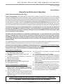
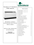
Model Nomenclature
1
2
3
4
TO V F
5 6
7
8
9
30 C
F
E
10
11
12
13
14
3 A B
N
T A
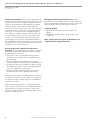
MODEL TYPE
TO = TRANQUILITY® (HFC-410A) OUTSIDE AIR
CONFIGURATION
HB = HORIZONTAL w/WHEEL AND BYPASS DAMPER
HD = HORIZONTAL NO WHEEL
HW = HORIZONTAL w/ WHEEL
RB = ROOFTOP w/WHEEL AND BYPASS DAMPER
RD = ROOFTOP (OUTDOOR) NO WHEEL
RW = ROOFTOP ( OUTDOOR ) w/ WHEEL
VF = VERTICAL w/ FILTER BOX (STANDARD)
VD = VERTCAL w/DAMPER BOX
SUPPLY MOTOR HP
OPTION MOTOR HP w/ VFD
0.5
A
1
B
1.5
C
2
D
E
3
5
F
7.5
G
10
H
J
15
20
K
25
L
30
M
X
0.5
N
1
P
X
1.5
Q
X
2
X
R
3
X
S
5
X
T
7.5
X
U
10
X
V
15
X
W
20
X
1
X
2
25
30
X
3
UNIT SIZE
02
03
04 - (VD, VF)
05
08
10
15
20
OPTION
25
G
30
{
ALL
CONFIGURATIONS
{
HD / RD
CONFIGURATION
36
40
46
50
56
60
H
F
N
A
B
C
D
J
K
L
M
Y
P
R
W
REVISION LEVEL
C = CAREL
VOLTAGE
208-230/60/1
X
X
X
X
-
208-230/60/3
X
X
X
X
-
460/60/3
X
X
X
X
-
575/60/3 NON- FUSED DISC. GFI
X
X
X
X
X
X
X
X
X
X
X
X
X
X
X
X
X
X
X
X
COMMUNICATION OPTIONS
OPTION COMMUNICATION CONFIGURATION
1
CONTROLLER WITH NO BMS
2
3
CONTROLLER WITH BACnet Enet
CONTROLLER WITH BACnet MS/TP
4
5
CONTROLLER WITH LON
CONTROLLER WITH MODBUS
CONTROLS / MISC OPTIONS
E = LAT (STANDARD)
H = LAT (STANDARD), VFD FOR WHEEL
J = ZONE RESET
M = ZONE RESET, VFD FOR WHEEL
R = NIGHT SETBACK (HB, RB, & VD ONLY)
S = R + VFD FOR WHEEL
T = CO2
U = CO2, VFD FOR WHEEL
15
EXHAUST MOTOR HP
OPTION MOTOR HP
0.5
A
1
B
1.5
C
2
D
3
E
5
F
7.5
G
10
H
J
15
20
K
25
L
30
M
0.5
N
1
P
1.5
Q
2
R
3
S
5
T
7.5
U
10
V
15
W
1
20
2
25
3
30
w/ VFD
X
X
X
X
X
X
X
X
X
X
X
X
SUPPLY AIR CONFIGURATION
OPTION
TOP
BOTTOM DISCHARGE
REAR DISCHARGE
STANDARD
FILTER
T
B
A
MERV 13
STANDARD FILTER MERV 13
WITH PRE-FILTER FILTER WITH PRE-FILTER
F
C
J
G
D
K
H
E
L
RETURN AIR CONFIGURATION
OPTION
NONE (NO WHEEL)
REAR RETURN
BOTTOM RETURN
STANDARD
FILTER
N
A
B
MERV 13
STANDARD FILTER MERV 13
FILTER WITH PRE-FILTER
WITH PRE-FILTER
E
C
G
F
D
H
HEAT EXCHANGER OPTIONS
COATED
OPTION NON-COATED
COIL
COIL
X
B
X
C
X
K
X
L
X
M
X
N
X
P
R
X
SIDE WATER
CONNECTION
BOTTOM WATER
CONNECTION
LEFT HAND
ACCESS
X
X
X
X
-
X
X
X
X
X
X
X
X
RIGHT HAND
ACCESS
X
X
X
X
-
LH
O/A >
(FRONT)
TOP VIEW
REAR
RH
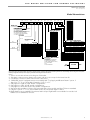
NOTE: A dedicated 115 VAC, 15 Amp circuit (by others) is required on all DOAS units for operation of the factory installed evaporator heat tape(s). Failure to connect heat tape(s) to a
proper power supply may lead to freezing of the water in the heat exchanger. Failure of, and/or damage caused by the failure of a heat exchanger due to freezing will be exempt from
warranty coverage if the heat tapes are not properly connected and working at the time of the failure.
Notes:
1.
2.
3.
4.
Service access side referenced looking into O/A intake.
Side water connections are always on the same side as access except for horizontal size 20.
Condensate connection same side as water connections.
“HW & RW” model configurations are not available with “Top Supply with Bottom Return” option. if
digit 14 is “T, F, C, or J” then digit 13 must be “A, E, C, or G”.
5. Only applies to “RW” & “HW” model configurations.
6. Only applies to “RB” & “HB” model configurations.
7. Only applies to horizontal and rooftop model configurations.
8. Vertical models use Merv 11 filters only; horizontal and rooftop models use Merv 7 filters as standard.
9. If digit 9 is option “T” or “U”, then vfd will need to be selected in digits 11 and 15.
10. Right hand access is standard for horizontal and rooftops. Right hand is not available for verticals. Left
hand access is standard for verticals.
c l i m a t e m a s t e r. c o m
3
CLIMATEMASTER WATER-SOURCE HEAT PUMPS
Vertical DOAS
R e v. : 0 1 / 3 1 / 1 3
General Information
Safety
Warnings, cautions, and notices appear throughout this
manual. Read these items carefully before attempting any
installation, service, or troubleshooting of the equipment.
CAUTION: Indicates a potentially hazardous situation or
an unsafe practice, which if not avoided could result in
minor or moderate injury or product or property damage.
DANGER: Indicates an immediate hazardous situation,
which if not avoided will result in death or serious injury.
DANGER labels on unit access panels must be observed.
NOTICE: Notification of installation, operation, or
maintenance information, which is important, but which is
not hazard-related.
WARNING: Indicates a potentially hazardous situation,
which if not avoided could result in death or serious injury.
WARNING!
WARNING!
WARNING! The unit label will indicate which refrigerant is
provided. The EarthPure® Application and Service Manual
should be read and understood before attempting to service
refrigerant circuits with HFC-410A.
WARNING!
WARNING! To avoid the release of refrigerant into the
atmosphere, the refrigerant circuit of this unit must be
serviced only by technicians who meet local, state, and
federal proficiency requirements.
WARNING!
WARNING! All refrigerant discharged from this unit must
be recovered WITHOUT EXCEPTION. Technicians must
follow industry accepted guidelines and all local, state, and
federal statutes for the recovery and disposal of refrigerants.
If a compressor is removed from this unit, refrigerant circuit
oil will remain in the compressor. To avoid leakage of
compressor oil, refrigerant lines of the compressor must be
sealed after it is removed.
CAUTION!
CAUTION! To avoid equipment damage, DO NOT use
these units as a source of heating or cooling during the
construction process. The mechanical components and filters
will quickly become clogged with construction dirt and debris,
which may cause system damage.
WARNING! The installation of water-source heat pumps and
all associated components, parts, and accessories which
make up the installation shall be in accordance with the
regulations of ALL authorities having jurisdiction and MUST
conform to all applicable codes. It is the responsibility of
the installing contractor to determine and comply with ALL
applicable codes and regulations.
4
C l i m a t e M a s t e r Wa t e r - S o u r c e H e a t P u m p s
THE SMART SOLUTION FOR ENERGY EFFICIENCY
Vertical DOAS
R e v. : 0 1 / 3 1 / 1 3
Inspection - ClimateMaster DOAS units are not designed
to support the weight of a person on all portions of the
unit roof. Personnel should avoid stepping on the top of
the unit. However, if it is necessary to stand on the roof,
stay within 18” of the cabinet perimeter.
ClimateMaster inspects and tests each DOAS unit before
it leaves the factory so that you receive a quality piece
of equipment. However, the DOAS unit may have been
damaged in transit. Check the equipment thoroughly for
both visible and concealed damage before you sign the
receiving papers. Pay particular attention to the roof of the
unit on outdoor units. Document any damage in writing
on the carrier’s bill of lading to ensure that damage claims
are handled promptly. If the unit has been damaged,
obtain a claim form from the carrier. Promptly fill out and
return the form, and notify ClimateMaster of any damage.
DAMAGE CLAIMS OR SHORTAGES MUST BE FILED
WITH THE FREIGHT CARRIER WITHIN 5 WORKING DAYS
OF RECEIPT OF EQUIPMENT.
Storage - Equipment should be stored in its original
packaging in a clean, dry area. Store units in an upright
position at all times. Do not stack units or any other
equipment on any DOAS unit.
Unit Protection - Cover units on the job site with either
the original packaging or an equivalent protective
covering. Cap the open ends of pipes stored on the
job site. In areas where painting, plastering, and/or
spraying has not been completed, all due precautions
must be taken to avoid physical damage to the units and
contamination by foreign material. Physical damage and
contamination may prevent proper start-up and may result
in costly equipment clean-up.
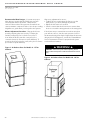
Allow a minimum of 36 inches of clearance around
the service side of the DOAS unit for piping, electrical
connections, and service access. Install the unit on a
sturdy, level mounting base or platform that will prevent
vibration and sound transmission. Never install the DOAS
unit on a wooden platform. Do not install the unit near
occupied rooms such as offices or guestrooms. Do not
attempt to conserve installation space by fabricating
restrictive ductwork with abrupt bends. You may reduce
the operating efficiency and the moisture removal capacity
of the DOAS unit. See duct system installation section for
detailed duct installation instructions.
NOTICE! - YOU MUST NOT INSTALL AN INDOORRATED DOAS UNIT IN AN OUTDOOR OR A WET
ENVIRONMENT. If you must install the DOAS unit outside
you must use an outdoor-rated DOAS unit. ClimateMaster
seals and weatherproofs outdoor DOAS units to help
prevent water infiltration. You can determine whether your
DOAS unit is outdoor-rated by inspecting the unit rating
plate (see Section 4.1 for details).
Prepare units for installation as follows:
1. Compare the electrical data on the unit nameplate
with ordering and shipping information to verify that
the correct unit has been shipped.
2. Keep the cabinet covered with the original packaging
until installation is complete and all plastering,
painting, etc. is finished.
3. Verify refrigerant tubing is free of kinks or dents and
that it does not touch other unit components.
4. Inspect all electrical connections. Connections must
be clean and tight at the terminals.
5. Some accessory items such as sensor(s), interface
module, etc may be shipped packed in the
compressor compartment.
Examine all pipes, fittings, and valves before installing
any of the system components. Remove any dirt or debris
found in or on these components.
Pre-Installation - ClimateMaster 100% outdoor air DOAS
units designed for indoor installations are configured
to allow single-side access to regularly maintained
components. This means you can make your service
connections and perform routine maintenance even when
you must install one side of the DOAS unit against a wall
or other restriction. The “service side” is determined when
the order is placed at the factory. Note that the service
side cannot be changed in the field. It is recommended
that clearance be provided on all sides to allow for ease
of servicability in the event large components require
replacement.
c l i m a t e m a s t e r. c o m
5
CLIMATEMASTER WATER-SOURCE HEAT PUMPS
Vertical DOAS
R e v. : 0 1 / 3 1 / 1 3
Rigging - ClimateMaster DOAS units are solidly built and
can be very heavy. Avoid personal injury and damaged
equipment by planning the installation carefully. Use
moving equipment whenever possible.
Moving the DOAS Unit - Use hand trucks, equipment
dollies or pipe rollers to move the DOAS Unit into place.
Use caution so that the DOAS Unit does not tip over.
CAUTION!
CAUTION! All three phase scroll compressors must have
direction of rotation verified at start-up. Verification is
achieved by checking compressor Amp draw. Amp draw
will be substantially lower compared to nameplate values.
Additionally, reverse rotation results in an elevated sound
level compared to correct rotation. Reverse rotation will result
in compressor internal overload trip within several minutes.
Verify compressor type before proceeding.
CAUTION!
CAUTION! Do not tip the DOAS unit on its side. Avoid
dropping the unit down stairways or subjecting it to severe
mechanical shock. You may seriously damage the unit!
Failure to observe these instructions may lead to equipment
damage, personal injury, or death.
CAUTION!
CAUTION! DO NOT store or install units in corrosive
environments or in locations subject to temperature or
humidity extremes (e.g., attics, garages, rooftops, etc.).
Corrosive conditions and high temperature or humidity can
significantly reduce performance, reliability, and service life.
Always move and store units in an upright position. Tilting
units on their sides may cause equipment damage.
CAUTION!
CAUTION! CUT HAZARD - Failure to follow this caution may
result in personal injury. Sheet metal parts may have sharp
edges or burrs. Use care and wear appropriate protective
clothing, safety glasses and gloves when handling parts and
servicing heat pumps.
6
C l i m a t e M a s t e r Wa t e r - S o u r c e H e a t P u m p s
THE SMART SOLUTION FOR ENERGY EFFICIENCY
Vertical DOAS
R e v. : 0 1 / 3 1 / 1 3
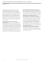
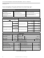
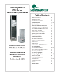
Unit Connections and Service Clearances 4-15 Tons
TOV 4-15 Tons
Utility
Location
Electrical Access
See Drawing
Service Access
Primary Side & Left Side
Filter Access
Left Side
Water Cooled
Piping Connection(s)
Left (See Drawing)
Condensate Drain
Left (See Drawing)
Notes:
1. Primary Side Access: 4 & 5 HP Units require 3’ - 0” clearance due to electrical panel. 8, 10, & 15 HP Units
require a minimum of 2’ - 0” for service clearance, but 3’-0” is preferred.
2. Left Service Side Access: Requires 3’-0” access clearance for service and filter access.
3. If water piping or condensate drain is provided on the right side of the unit opposite the left hand shown, provide
adequate space for field connection and any piping specialties.
c l i m a t e m a s t e r. c o m
7
CLIMATEMASTER WATER-SOURCE HEAT PUMPS
Vertical DOAS
R e v. : 0 1 / 3 1 / 1 3
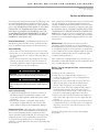
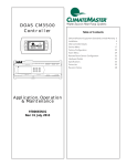
Unit Connections and Service Clearances 20-30 Tons
TOV 20-30 Tons
Utility
Location
Electrical Access
Primary Service Side
Service Access
Primary Side & Left Side
Filter Access
Left Side
Water Cooled
Piping Connection(s)
Left (See Drawing)
Condensate Drain
Left Side
Notes:
1. Primary Service Side Access require 3’ - 0” clearance due to electrical panel.
2. Left Service Side Access: Requires 3’-0” access clearance for service and filter access. The unit shown
above is standard Left Hand Access. A unit that is Right Hand Access will mirror the left hand access
shown above.
8
C l i m a t e M a s t e r Wa t e r - S o u r c e H e a t P u m p s
c l i m a t e m a s t e r. c o m
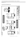
LEFT SIDE
(SERVICE ACCESS) VIEW
3.44
Y
Z
28.48
X
24.96
24.82
OUTLET
1 3/8" O.D.
INLET
1" I.D.
OUTLET
CONDENSATE
DRAIN
CONNECTION
RIGHT SIDE VIEW
(NO ACCESS)
32.09 WIDTH**
38.95 OVERALL WIDTH
10.47"
110-10
W
13.60"
110-4
BLOWER MODEL
1 3/8" O.D.
WATER COOLED AND HEAT PUMP
CONDENSER CONNECTIONS
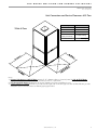
FRONT SIDE
(O/A INTAKE) VIEW
DISCHARGE VIEW
W
** ADD APPROXIMATELY 0.5 IN. FOR EXTERIOR PANEL FASTENERS
* APPROXIMATE DIMENSION
NOTES:
1.
FRONT OF UNIT LOOKING
INTO OUTDOOR AIR INTAKE,
WATER CONNECTIONS
LEFT SIDE ONLY.
22.98
36.19
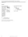
Vertical 4-5 Ton Cabinet
X
13.12"
6.87"
Y
Z
3.00*
34.15 LENGTH**
Part weight
Third Angle Projection
All Dimensions in Inches
All Angles 90
All outside corners 0.125" fillet
Unless Otherwise Specified
BACK SIDE
(SERVICE ACCESS) VIEW
7.00"
7.13"
ALL DIMENSIONS ARE IN INCHES
TOLERANCE 1/8"
ELECTRICAL
ENCLOSURE
LOCATION
58.42
CABINET
HEIGHT
60.11
OVERALL
HEIGHT
12.50"
12.50"
Scale
Sheet
Drawn
1/3
Rev.
5
9/12/2002
Date Released
1:20
SK
Tolerance Unless
Otherwise Specifed
X.X
.125
X.XX
.060
X.XXX
.030
Angles
1
4-5 TON CABINET
Vertical Discharge
GENERAL ARRANGEMENT
Drawing Number
Page Title
Description
Geothermal Heat Pump Systems
WATER CONNECTIONS AND
CONDENSATE STUB LOCATION
3' SERVICE CLEARANCE REQUIRED
THE SMART SOLUTION FOR ENERGY EFFICIENCY
Vertical DOAS
R e v. : 0 1 / 3 1 / 1 3
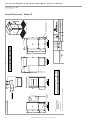
Vertical Dimensional Data Model 04 & 05
9
10
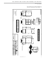
LEFT SIDE
(SERVICE ACCESS) VIEW
C l i m a t e M a s t e r Wa t e r - S o u r c e H e a t P u m p s
4.47
ELECTRICAL
ENCLOSURE
LOCATION
Y
Z
DISCHARGE VIEW
38.94
X
29.96
24.82
W
19.60"
16.47"
BLOWER MODEL
110-4
110-10
OUTLET
1 3/8" O.D.
INLET
1 3/8" O.D.
1" I.D.
OUTLET
CONDENSATE
DRAIN
CONNECTION
RIGHT SIDE VIEW
(NO ACCESS)
35.09 WIDTH**
41.95 OVERALL WIDTH
WATER COOLED AND HEAT PUMP
CONDENSER CONNECTIONS
FRONT SIDE
(O/A INTAKE) VIEW
W
** ADD APPROXIMATELY 0.5 IN. FOR EXTERIOR PANEL FASTENERS
* APPROXIMATE DIMENSION
NOTES:
1.
FRONT OF UNIT LOOKING
INTO OUTDOOR AIR INTAKE,
WATER CONNECTIONS
LEFT SIDE ONLY.
27.98
51.19
Vertical 8-10 Ton Cabinet
X
Y
12.50"
12.50"
Z
Part weight
Third Angle Projection
All Dimensions in Inches
All Angles 90
All outside corners 0.125" fillet
Unless Otherwise Specified
3.00*
BACK SIDE
(SERVICE ACCESS) VIEW
46.15 LENGTH**
8.88"
8.88"
ALL DIMENSIONS ARE IN INCHES
TOLERANCE 1/8"
78.42
CABINET
HEIGHT
80.11
OVERALL
HEIGHT
13.12"
6.87"
Scale
Sheet
Drawn
2/3
Rev.
5
9/12/2002
Date Released
1:24
SK
Tolerance Unless
Otherwise Specifed
X.X
.125
X.XX
.060
X.XXX
.030
Angles
1
8-10 TON CABINET
Vertical Discharge
GENERAL ARRANGEMENT
Drawing Number
Page Title
Description
Geothermal Heat Pump Systems
WATER CONNECTIONS AND
CONDENSATE STUB LOCATION
3' SERVICE CLEARANCE REQUIRED
CLIMATEMASTER WATER-SOURCE HEAT PUMPS
Vertical DOAS
R e v. : 0 1 / 3 1 / 1 3
Vertical Dimensional Model 08 & 10
THE SMART SOLUTION FOR ENERGY EFFICIENCY
Vertical DOAS
R e v. : 0 1 / 3 1 / 1 3
Vertical Dimensional Data Model 15
Vertical 15 Ton Cabinet
51.19
27.98
LEFT SIDE
(SERVICE ACCESS) VIEW
NOTES:
1.
FRONT OF UNIT LOOKING
INTO OUTDOOR AIR INTAKE,
WATER CONNECTIONS
LEFT SIDE ONLY.
* APPROXIMATE DIMENSION
Z
Y
4.47
ELECTRICAL
ENCLOSURE
LOCATION
W
X
38.94
DISCHARGE VIEW
FRONT SIDE
(O/A INTAKE) VIEW
39.50
29.93
1 5/8" O.D.
INLET
1 5/8" O.D.
OUTLET
WATER COOLED AND HEAT PUMP
CONDENSER CONNECTIONS
** ADD APPROXIMATELY 0.5 IN. FOR EXTERIOR PANEL FASTENERS
110-10
15.22"
16.47"
W
15.62"
13.12"
X
13.53"
12.50"
Y
8.38"
8.88"
Z
Part weight
Third Angle Projection
All Dimensions in Inches
All Angles 90
All outside corners 0.125" fillet
Unless Otherwise Specified
BACK SIDE
(SERVICE ACCESS) VIEW
3.00*
46.15 LENGTH**
120-12
78.42
CABINET
HEIGHT
80.11
OVERALL
HEIGHT
BLOWER MODEL
41.95 OVERALL WIDTH
35.09 WIDTH**
RIGHT SIDE VIEW
(NO ACCESS)
OUTLET
CONDENSATE
DRAIN
CONNECTION
1" I.D.
ALL DIMENSIONS ARE IN INCHES
TOLERANCE 1/8"
3' SERVICE CLEARANCE REQUIRED
Rev.
5
Description
Page Title
15 TON CABINET
GENERAL ARRANGEMENT
Drawing Number
Vertical Discharge
Geothermal Heat Pump Systems
WATER CONNECTIONS AND
CONDENSATE STUB LOCATION
3/3
9/12/2002
Date Released
1:24
SK
Tolerance Unless
Otherwise Specifed
X.X
.125
X.XX
.060
X.XXX
.030
Angles
1
Drawn
Sheet
Scale
11
c l i m a t e m a s t e r. c o m
12
C l i m a t e M a s t e r Wa t e r - S o u r c e H e a t P u m p s
RIGHT SIDE VIEW
11.000*
* APPROXIMATE DIMENSION
7.565
5.000*
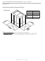
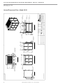
Vertical 20-30 Ton LH Access
8.625
7.000*
OPTIONAL CONDENSATE
DRAIN LOCATION
ELECTRICAL
COMPARTMENT
LEFT-HAND ACCESS
ELECTRICAL ENTRY
10.840
40.000
BACK PRIMARY SERVICE ACCESS VIEW
77.250 OVERALL LENGTH
TOP DISCHARGE VIEW
11.000*
60.000
DISCHARGE OPENING
11.000*
61.519
OVERALL WIDTH
Part Based On
Finish
Material
LEFT SIDE SERVICE ACCESS VIEW
2.625*
54.000
CABINET WIDTH
RIGHT-HAND ACCESS
ELECTRICAL ENTRY
69.971
OVERALL
HEIGHT
7.000*
STD. CONDENSATE
DRAIN LOCATION
5.000*
12.000*
TYP
3.341
23.500 *
Part weight
Third Angle Projection
Drawn
Scale
Sheet
SK
1:32
1/1
Rev.
4/23/04
Date Released
0
23.500*
Tolerance Unless
Otherwise Specifed
X.X
± .125
X.XX
± .060
X.XXX
± .030
Angles ± 1°
FRONT O/A INTAKE VIEW
10.000*
TYP
70.568
INTAKE OPENING
All Dimensions in Inches
All Angles 90°
All Outside Corners 0.094" Radius
Unless Otherwise Specified
8.242
43.516
INTAKE
OPENING
LEFT-HAND
WATER CONNECTIONS
(3) 870-012
24x24x4 AIR FILTERS
(3) 870-041
20x24x4 AIR FILTERS
GENERAL ASSEMBLY
Vertical 20-30 Ton Cabinet
Drawing Number
Page Title
Description
Geothermal Heat Pump Systems
6.000* TYP
RIGHT-HAND
WATER CONNECTIONS
CLIMATEMASTER WATER-SOURCE HEAT PUMPS
Vertical DOAS
R e v. : 0 1 / 3 1 / 1 3
Vertical Dimensional Data - Model 20-30
THE SMART SOLUTION FOR ENERGY EFFICIENCY
Vertical DOAS
R e v. : 0 1 / 3 1 / 1 3
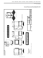
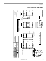
Vertical Dimensional Model 04 & 05
Vertical 4-5 Ton & Mixing Box
36.19
22.98
LEFT SIDE
(SERVICE ACCESS) VIEW
NOTES:
1.
FRONT OF UNIT LOOKING
INTO OUTDOOR AIR INTAKE,
WATER CONNECTIONS
LEFT SIDE ONLY.
* APPROXIMATE DIMENSION
DISCHARGE VIEW
Z
Y
** ADD APPROXIMATELY 0.5 IN. FOR EXTERIOR PANEL FASTENERS
W
X
FRONT SIDE
(O/A INTAKE) VIEW
INLET
1 3/8" O.D.
OUTLET
WATER COOLED AND HEAT PUMP
CONDENSER CONNECTIONS
1 3/8" O.D.
110-4
BLOWER MODEL
10.47"
13.60"
W
13.12"
6.87"
X
12.50"
12.50"
Y
7.00"
7.13"
Z
ELECTRICAL
ENCLOSURE
LOCATION
60.11
OVERALL
HEIGHT
58.42
CABINET
HEIGHT
110-10
RIGHT SIDE VIEW
(NO ACCESS)
32.09 UNIT WIDTH**
54.21 OVERALL WIDTH**
OUTLET
CONDENSATE
DRAIN
CONNECTION
1" I.D.
ALL DIMENSIONS ARE IN INCHES
TOLERANCE 1/8"
34.15 LENGTH**
Drawn
Sheet
Scale
Rev.
5
4-5 TON CABINET
GENERAL ARRANGEMENT
Drawing Number
Page Title
Vertical Discharge w/ OA Mixing Box
Description
Geothermal Heat Pump Systems
WATER CONNECTIONS AND
CONDENSATE STUB LOCATION
3' SERVICE CLEARANCE REQUIRED
1/3
2/17/2003
Date Released
1:20
SK
Tolerance Unless
Otherwise Specifed
X.X
.125
X.XX
.060
X.XXX
.030
Angles
1
3.00*
BACK SIDE
(SERVICE ACCESS) VIEW
All Dimensions in Inches
All Angles 90
All outside corners 0.125" fillet
Unless Otherwise Specified
Third Angle Projection
Part weight
13
c l i m a t e m a s t e r. c o m
CLIMATEMASTER WATER-SOURCE HEAT PUMPS
Vertical DOAS
R e v. : 0 1 / 3 1 / 1 3
Vertical 20-30 Ton & Mixing Box
Vertical With Damper Box Dimensional Data - Model 20 - 30
14
C l i m a t e M a s t e r Wa t e r - S o u r c e H e a t P u m p s
THE SMART SOLUTION FOR ENERGY EFFICIENCY
Vertical DOAS
R e v. : 0 1 / 3 1 / 1 3
Vertical Dimensional - Model 08 & 10
Vertical 8-10 Ton & Mixing Box
51.19
27.98
Z
W
X
FRONT SIDE
(O/A INTAKE) VIEW
1 3/8" O.D.
INLET
1 3/8" O.D.
OUTLET
WATER COOLED AND HEAT PUMP
CONDENSER CONNECTIONS
Y
ELECTRICAL
ENCLOSURE
LOCATION
DISCHARGE VIEW
LEFT SIDE
(SERVICE ACCESS) VIEW
NOTES:
1.
FRONT OF UNIT LOOKING
INTO OUTDOOR AIR INTAKE,
WATER CONNECTIONS
LEFT SIDE ONLY.
* APPROXIMATE DIMENSION
** ADD APPROXIMATELY 0.5 IN. FOR EXTERIOR PANEL FASTENERS
OUTLET
CONDENSATE
DRAIN
CONNECTION
1" I.D.
110-4
16.47"
19.60"
W
13.12"
6.87"
X
12.50"
12.50"
Y
8.88"
8.88"
Z
78.42
CABINET
HEIGHT
110-10
80.11
OVERALL
HEIGHT
46.15 LENGTH**
3.00*
Drawn
Sheet
Scale
2/3
5
8-10 TON CABINET
GENERAL ARRANGEMENT
Drawing Number
Page Title
Vertical Discharge w/ OA Mixing Box
Description
Geothermal Heat Pump Systems
WATER CONNECTIONS AND
CONDENSATE STUB LOCATION
3' SERVICE CLEARANCE REQUIRED
Rev.
2/17/2003
Date Released
1:24
SK
Tolerance Unless
Otherwise Specifed
X.X
.125
X.XX
.060
X.XXX
.030
Angles
1
BACK SIDE
(SERVICE ACCESS) VIEW
Part weight
Third Angle Projection
All Dimensions in Inches
All Angles 90
All outside corners 0.125" fillet
Unless Otherwise Specified
BLOWER MODEL
35.09 UNIT WIDTH**
57.21 OVERALL WIDTH**
22.12
MIXING
BOX
RIGHT SIDE VIEW
(NO ACCESS)
ALL DIMENSIONS ARE IN INCHES
TOLERANCE 1/8"
15
c l i m a t e m a s t e r. c o m
16
LEFT SIDE
(SERVICE ACCESS) VIEW
C l i m a t e M a s t e r Wa t e r - S o u r c e H e a t P u m p s
ELECTRICAL
ENCLOSURE
LOCATION
DISCHARGE VIEW
X
FRONT SIDE
(O/A INTAKE) VIEW
W
OUTLET
1 5/8" O.D.
INLET
1 5/8" O.D.
WATER COOLED AND HEAT PUMP
CONDENSER CONNECTIONS
Y
** ADD APPROXIMATELY 0.5 IN. FOR EXTERIOR PANEL FASTENERS
* APPROXIMATE DIMENSION
NOTES:
1.
FRONT OF UNIT LOOKING
INTO OUTDOOR AIR INTAKE,
WATER CONNECTIONS
LEFT SIDE ONLY.
27.98
51.19
Vertical 15 Ton & Mixing Box
1" I.D.
OUTLET
CONDENSATE
DRAIN
CONNECTION
15.22"
110-10
120-12
26.12
MIXING
BOX
X
15.62"
13.12"
Y
78.42
HEIGHT
79.36
OVERALL
HEIGHT
13.53"
12.50"
ALL DIMENSIONS ARE IN INCHES
TOLERANCE 1/8"
RIGHT SIDE VIEW
(NO ACCESS)
35.09 UNIT WIDTH**
61.21 OVERALL WIDTH**
W
16.47"
BLOWER MODEL
Z
46.15 LENGTH**
Part weight
Third Angle Projection
All Dimensions in Inches
All Angles 90
All outside corners 0.125" fillet
Unless Otherwise Specified
Scale
Sheet
Drawn
3/3
Rev.
5
2/17/2003
15 TON CABINET
GENERAL ARRANGEMENT
Drawing Number
Page Title
Vertical Discharge w/ OA Mixing Box
Description
Geothermal Heat Pump Systems
WATER CONNECTIONS AND
CONDENSATE STUB LOCATION
3' SERVICE CLEARANCE REQUIRED
Date Released
1:24
SK
Tolerance Unless
Otherwise Specifed
X.X
.125
X.XX
.060
X.XXX
.030
Angles
1
3.00*
BACK SIDE
(SERVICE ACCESS) VIEW
8.38"
8.88"
CLIMATEMASTER WATER-SOURCE HEAT PUMPS
Vertical DOAS
R e v. : 0 1 / 3 1 / 1 3
Vertical Dimensional - Model 15
THE SMART SOLUTION FOR ENERGY EFFICIENCY
Vertical DOAS
R e v. : 0 1 / 3 1 / 1 3
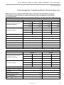
TO VF/VD Physical Data Table
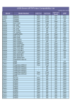
Model
Fan motor available H.P.
Blower wheel size
4
5
0.5/1.0/1.5/2.0
11-04/11-10
Compressor type/qty
8
10
0.5/1.0/1.5/2.0
0.5/1.0/1.5
0.5/1.0/1.5/2.0
11-04/11-10
11-04/11-10
11-10
Scroll, 1 ea.
Scroll 2ea. (1 tandem set)
Factory charge lb/unit
HFC-410A Tranquility units
Water Connection Size “ O.D.
Water Flow Rate GPM
13 [208]
15 [240]
20 [320]
26 416]
7/8"
1/18"
1 3/8"
13/8"
17
19
26
34
Water Pressure Drop PSI/Ft
5.3/12.23
4.0/9.23
5.4/12.46
6.6/15.22
Condensate Connection Size
1"
1"
1"
1"
(1) 25 X 29 X 4
(1) 25 X 29 X 4
(2) 20 X 25 X 4
(2) 20 X 25 X 4
Miscellaneous Data
Filter qty/size
Filter Type
Merv 11, Pleated
Operating Weight
626
643
940
1002
Shipping Weight
639
666
965
1033
Model
Fan motor available H.P.
Blower wheel size
15
20
25
30
1.0/1.5/20./3.0
1.0/1.5/20./3.0/5.0/7.5
1.0/1.5/20./3.0/5.0/7.5
1.0/1.5/20./3.0/5.0/7.5
11-10/12-12
APAF18-T2
APAF18-T2
APAF18-T2
Compressor type/qty
Scroll 2ea. (1 tandem set)
Factory charge lb/unit
HFC-410A Tranquility units
40 [640]
62 [992]
N/A
87 [1392]
15/8"
25/8"
25/8"
25/8"
49
69
84
102
Water Pressure Drop PSI/Ft
9.4/21.68
6.2/14.30
6.2/14.30
7.1/16.38
Condensate Connection Size
1"
1"
1"
1"
(4) 20 X 20 X 4
(3) 20 X 24 X 4 (3) 24 X
24 X 4
(3) 20 X 24 X 4 (3) 24
X 24 X 4
(3) 20 X 24 X 4 (3) 24 X
24 X 4
Operating Weight
1401
2467
2652
2771
Shipping Weight
1444
2569
2742
2886
Water Connection Size “ O.D.
Water Flow Rate GPM
Miscellaneous Data
Filter qty/size
Filter Type
Merv 11, Pleated
Note 1: A strainer is required on the ENTERING WATER connection to the DOAS unit.
The strainer must be provided and installed by others.
The strainer must be 60 mesh (250 Micron) or finer.
Failure to install a properly sized strainer can lead to premature fouling and possible failure
of a brazed plate heat exchanger.
DOAS units installed and operated without a properly sized strainer will not qualify for
warranty coverage.
Note 2: A dedicated 115 VAC, 15 Amp circuit (by others) is required on all DOAS units
for operation of the factory installed evaporator heat tape(s). Failure to connect heat
tape(s) to a proper power supply may lead to freezing of the water in the heat exchanger.
Failure of, and/or damage caused by the failure of a heat exchanger due to freezing will be
exempt from warranty coverage if the heat tapes are not properly connected and working
at the time of the failure.
c l i m a t e m a s t e r. c o m
17
CLIMATEMASTER WATER-SOURCE HEAT PUMPS
Vertical DOAS
R e v. : 0 1 / 3 1 / 1 3
Vertical Installation
Condensate Piping – Vertical Units - The condensate
drain connection is on the side of the DOAS unit. Pitch
the drainpipe a minimum of 1/4 inch per linear foot, and
support it at least every 5 feet. If the drain runs through
an unconditioned space, you must install heat tracing to
prevent the moisture in the drain from freezing. NOTE:
While its supply blower runs, the inside of the DOAS Unit
operates at a negative pressure. Your Tranquility unit has
an internal factory-installed p-trap in the condensate
drain to prevent condensate from being drawn into the
cabinet of the DOAS unit.
18
CAUTION!
CAUTION! Ensure condensate line is pitched toward drain
1/8 inch per ft [11mm per m] of run.
C l i m a t e M a s t e r Wa t e r - S o u r c e H e a t P u m p s
THE SMART SOLUTION FOR ENERGY EFFICIENCY
Vertical DOAS
R e v. : 0 1 / 3 1 / 1 3
Duct System Installation
Duct System Installation - Duct design and installations
should conform to the latest ASHRAE and SMACNA
low velocity duct standards Undersized, restrictive
ductwork with abrupt turns or transitions can decrease
the efficiency and the moisture removal capacity of
your DOAS unit. Size the ductwork for an acceptable air
pressure drop at the airflow volume of your DOAS unit.
Use neoprene flex connectors when you attach ductwork
to the DOAS unit to prevent transmission of excess
vibration and noise.
Select the grilles, registers and diffusers for low static
pressure loss, required throw distance, and the specified
CFM rating. You can find this information in most grille
manufacturer’s catalogs. If you are installing the grilles in
a corrosive environment, choose components made from
anodized aluminum.
If you must install ductwork in an unconditioned area, use
fiberglass duct wrap with vapor barrier facing. You must
install the outdoor air intake away from any sources of
airborne contamination such as exhaust fans or plumbing
vents. You can use galvanized sheet metal ducts for
most applications. However, you should use aluminum
or stainless steel ducts for extreme applications such as
chemical-laden environments.
Unit Air Flow - Each ClimateMaster DOAS unit is
designed to operate at a specified air flow rate. System
air flow must be checked prior to troubleshooting the
refrigeration circuit to assure that such problems are not
actually caused by improper unit air flow.
Problems with excessive airflow include:
• Reduction in moisture removal capacity.
• High amperage draw by the blower motor.
• Water carry over from evaporator coil.
• Excessive unit noise levels.
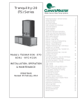
The total air flow of a ClimateMaster 20-ton through
30-ton system should be checked by measuring the air
pressure drop across only the reheat coil as shown in
Figure 2. Note: Port #1 is measuring the internal cabinet
pressure downstream of the evaporator (high side)
and port #2 is added to the discharge duct in the field,
downstream of the reheat coil (low side).
A Magnehelic® or inclined manometer with a range
of 0.0-1.0 inch water column will work well for this.
ClimateMaster DOAS units feature an adjustable blower
sheave to simplify air balancing. Utilize the following
procedure to determine system airflow:
1. Check the condition of the air filters and coils. Assure
that they are clean.
2. Check for any obvious restrictions in the ductwork.
3. Drive the outdoor air damper open, start the supply
air blower and energize the field-installed exhaust air
blower by turning on the “occupied” switch.
4. Use a Magnehelic® or inclined manometer to
measure the air pressure drop across ports #1 and #2.
Refer to Figures 1 & 2 to determine your unit cabinet
configuration and the air sampling port locations.
Compare this value to the value printed on the air flow
label on the side of the DOAS unit.
5. Change the air flow, if necessary, by adjusting the
motor pulley or any balancing dampers in the fieldinstalled ductwork.
Always measure the current draw of the blower motor
after you make any changes to the air flow quantity. If
the motor draws more than its FLA rating but the total
air flow is still low, check the resistance of the ductwork.
Verify that all grilles and dampers have been opened
and that there are no sudden turns or restrictions in the
ductwork.
WARNING!
Problems with inadequate airflow include:
• Violation of ventilation codes.
• Risk of evaporator coil freezing.
• Possibility of premature compressor failure.
WARNING! - Disconnect power before adjusting blower. Failure
to disconnect power could result in death or serious injury.
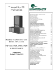
Determining System Air Flow - The total air flow of a
ClimateMaster 4-ton through 15-ton system should be
checked by measuring the air pressure drop across both
the evaporator and reheat coil between port #1 (low side)
and port #2 (high side) as shown in Figure 1.
c l i m a t e m a s t e r. c o m
19
CLIMATEMASTER WATER-SOURCE HEAT PUMPS
Vertical DOAS
R e v. : 0 1 / 3 1 / 1 3
Recommended Duct Designs - You must use proper
duct design to ensure that the DOAS unit operates
efficiently and without problems. Undersized or
restrictive ducts reduce the system air flow which can
cause premature compressor failure. Use the proceeding
diagrams as a guide when you design the duct system.
After every adjustment be sure to:
• Tighten the set screw against the flat spot on the
pulley hub so you don’t damage any threads.
• Adjust the belt tension if needed.
• Check to assure that the blower motor current draw
does not exceed the rating printed on the rating plate.
Blower Adjustment Procedure - Change the blower
speed by adjusting the motor pulley. To adjust the
variable pitch pulley, first loosen the set screw. To
slow down the blower, turn the outer pulley face
counterclockwise (to decrease its pitch diameter). To
speed up the blower, turn the outer pulley face clockwise
(to increase its pitch diameter).
If the blower motor current draw exceeds its rating but
your airflow is still too low, the static pressure losses in
the ductwork and grilles may be higher than the unit was
designed for. If this happens, consult the ClimateMaster
Service Department. Please be prepared with system
serial and model number.
Figure 1: Air Balance Ports for Models 4 - 15 Ton
Cabinets
WARNING!
WARNING! - Disconnect power before adjusting blower.
Failure to disconnect power could result in death or serious
injury.
Figure 2: Air Balance Ports for Models 20 - 30 Ton
Cabinets
20
C l i m a t e M a s t e r Wa t e r - S o u r c e H e a t P u m p s
THE SMART SOLUTION FOR ENERGY EFFICIENCY
Vertical DOAS
R e v. : 0 1 / 3 1 / 1 3
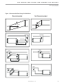
Figure 3: Recommended Duct Design for DOAS Units
Recommended
Not Recommended
30° or More
20° or Less
Discharge
Discharge
Duct Turns
5W or More for
Static Pressure Regain
Intake
Intake
Duct Turns
2.5W or More
Intake
Intake
Duct Turns
c l i m a t e m a s t e r. c o m
21
CLIMATEMASTER WATER-SOURCE HEAT PUMPS
Vertical DOAS
R e v. : 0 1 / 3 1 / 1 3
Piping Installation
WARNING!
WARNING! Polyolester Oil, commonly known as POE oil, is
a synthetic oil used in many refrigeration systems including
those with HFC-410A refrigerant. POE oil, if it ever comes
in contact with PVC or CPVS piping, may cause failure of
the PVC/CPVC. PVC/CPVC piping should never be used
as supply or return water piping with water source heat
pump products containing HFC-410A as system failures and
property damage may result.
CAUTION!
CAUTION! Corrosive system water requires corrosion
resistant fittings and hoses, and may require water treatment.
Table 1: Loop Flow Rates and Pressure Drop
CAUTION!
CAUTION! Do not bend or kink supply lines or hoses.
NOTICE! Do not allow hoses to rest against structural
building components. Compressor vibration may
be transmitted through the hoses to the structure,
causing unnecessary noise complaints.
CAUTION!
CAUTION! Piping must comply with all applicable codes.
Water Piping Installation - Your DOAS unit is equipped
with connections for a WSHP or geothermal loop. Use
standard piping practices when connecting to the DOAS
unit. A 60 mesh [250 micron] or finer strainer must be
installed in the water inlet line. Install an air eliminator
at any high points in the water piping. Air trapped in
the water circuit of the dehumidifier can lead to elevated
operating pressures, unexpected service calls and decreased equipment life. Flush field-installed piping thoroughly before you first put the dehumidifier into service.
To prevent premature failure of the heat exchanger,
maintain the water at a pH of 7.4, but never below 6.0. Do
not use water with high concentrations of sulfur, chlorine,
or sodium chloride.
A dedicated circulating pump must be used unless the
main pump can develop enough head to overcome the
combined resistance of the water condenser and the
piping connected to it. If the water system is connected
to a variable frequency drive or to water loops with
multiple units, flow regulating valves should be installed.
22
The flow rate and antifreeze concentration (if used)
will depend on your application. Standard water heat
exchangers are designed for the following entering fluid
conditions; 35 - 105°F with 0 - 30% glycol concentrations.
Standard flow rates and pressures for these conditions
are listed in Table 1a. Units with custom flow rates, head
pressures, entering water temperatures and/or glycol
concentrations that deviate from the listed standards
should reference the custom water flow label affixed to
the exterior cabinet of the dehumidifier next to the water
connections. It is a good practice and recommended
to always first refer to the flow rate and head pressure
shown on the label on the exterior of the unit.
Unit Size
Nominal Tons
04
05
08
10
15
20
25
30
Building or Geothermal Loop
GPM
17
19
26
34
49
69
84
102
Pressure Drop in PSI
5.3
4.0
5.4
6.6
9.4
6.2
6.2
7.1
Notes:
• All pressures in PSI/FT HD
• Building loop temperature range must be pure
water between 55°F and 95°F. Geothermal loop
temperature range must be 30% glycol between
35°F and 105°F.
• Consult factory for applications outside of these
conditions.
• Install an air eliminator at any high points in the
water piping. Air trapped in the water circuit of
the DOAS unit can lead to elevated operating
pressures, unexpected service calls, and decreased
equipment life.
• ClimateMaster strongly recommends all piping
connections, both internal and external to the unit,
be pressure tested for leakage by an appropriate
method prior to any finishing of the interior space
or before access to all connections is limited.
ClimateMaster will not be responsible or liable for
damages from water leaks due to inadequate or a
lack of pressurized leak testing during installation.
WARNING!
WARNING! Excessive flow rates will erode the water heat
exchanger(s) and piping!
C l i m a t e M a s t e r Wa t e r - S o u r c e H e a t P u m p s
THE SMART SOLUTION FOR ENERGY EFFICIENCY
Vertical DOAS
R e v. : 0 1 / 3 1 / 1 3
Water Quality Standards
Table 2: Water Quality Standards
Water Quality
Parameter
HX
Material
Closed
Recirculating
Open Loop and Recirculating Well
Scaling Potential - Primary Measurement
Above the given limits, scaling is likely to occur. Scaling indexes should be calculated using the limits below.
pH/Calcium Hardness
Method
All
-
pH < 7.5 and Ca Hardness <100ppm
Index Limits for Probable Scaling Situations - (Operation outside these limits is not recommended)
Scaling indexes should be calculated at 150¯F for direct use and HWG applications,
and at 90¯F for indirect HX use. A monitoring plan should be implemented.
Ryznar
6.0 - 7.5
All
Stability Index
If >7.5 minimize steel pipe use.
-0.5 to +0.5
Langelier
All
If
<-0.5
minimize
steel
pipe
use.
Based upon 150 ¯F HWG and Direct
Saturation Index
well, 85¯F Indirect Well HX
Iron Fouling
Iron Fe 2+ (Ferrous)
(Bacterial Iron potential)
All
Iron Fouling
All
-
<0.2 ppm (Ferrous)
If Fe2+ (ferrous)>0.2 ppm with pH 6 - 8, O2<5 ppm check for iron bacteria
-
<0.5 ppm of Oxygen
Above this level deposition will occur.
Corrosion Prevention
6 - 8.5
pH
All
Hydrogen Sulfide (H2S)
All
Ammonia ion
as hydroxide, chloride,
nitrate and sulfate
compounds
All
6 - 8.5
Monitor/treat as
needed
-
Minimize steel pipe below 7 and no open tanks with pH <8
<0.5 ppm
At H2S>0.2 ppm, avoid use of copper and copper nickel piping or HX's.
Rotten egg smell appears at 0.5 ppm level.
Copper alloy (bronze or brass) cast components are OK to <0.5 ppm.
<0.5 ppm
Maximum Allowable at maximum water temperature.
Maximum
Chloride Levels
Copper
CuproNickel
304 SS
316 SS
Titanium
-
50¯F (10¯C)
<20ppm
<150 ppm
<400 ppm
<1000 ppm
>1000 ppm
75¯F (24¯C)
NR
NR
<250 ppm
<550 ppm
>550 ppm
100¯F (38¯C)
NR
NR
<150 ppm
< 375 ppm
>375 ppm
Erosion and Clogging
Particulate Size and
Erosion
All
<10 ppm of particles
<10 ppm (<1 ppm "sandfree" for reinjection) of particlesand a maximum
and a maximum
velocity of 6 fps. Filtered for maximum 250 micron size. Any particulate
velocity of 6 fps.
that is not removed can potentially clog components.
Filtered for maximum
250 micron size.
The ClimateMaster Water Quality Table provides water quality requirements for ClimateMaster coaxial heat exchangers. When water properties are outside of those
requirements, an external secondary heat exchanger must be used to isolate the heat pump heat exchanger from the unsuitable water. Failure to do so will void the
warranty for the coaxial heat exchanger.
Rev.: 3/30/12
Notes:
&ORVHG5HFLUFXODWLQJV\VWHPLVLGHQWLILHGE\Dclosed pressurized piping system. Recirculating open wells should observe the open recirculating design considerations.
15Application not recommended.
1RGHVLJQ0D[LPXP
c l i m a t e m a s t e r. c o m
23
CLIMATEMASTER WATER-SOURCE HEAT PUMPS
Vertical DOAS
R e v. : 0 1 / 3 1 / 1 3
Electrical Wiring - Line Voltage
WARNING!
WARNING! To avoid possible injury or death due to electrical
shock, open the power supply disconnect switch and secure
it in an open position during installation.
CAUTION!
CAUTION! Use only copper conductors for field installed
electrical wiring. Unit terminals are not designed to accept
other types of conductors.
Wire and Fuse Sizing - The field-installed power
supply wires and overcurrent devices must be sized
to handle the minimum ampacity of the DOAS unit
without exceeding the maximum fuse size rating. Both
the minimum ampacity and the maximum fuse size are
printed on the unit rating plate.
Electrical - Line Voltage - All field installed wiring, including electrical ground, must comply with the National
Electrical Code as well as all applicable local codes. Refer
to the unit electrical data for fuse sizes. Consult wiring
diagram for field connections that must be made by the
installing (or electrical) contractor. All final electrical connections must be made with a length of flexible conduit
to minimize vibration and sound transmission to the
building.
General Line Voltage Wiring - Be sure the available
power is the same voltage and phase shown on the unit
serial plate. Line and low voltage wiring must be done
in accordance with local codes or the National Electric
Code, whichever is applicable.
High Voltage Connections - On single phase units
the power supply must have 3 connections (2 power, 1
ground). On three phase units the power supply must
have 4 connections (3 power, 1 ground). Connect the
power supply wires to the main power block located in
the upper section of the electrical compartment.
Auxiliary Line Voltage Wiring - A dedicated 115 VAC,
15 Amp circuit (by others) is required on all DOAS units
for operation of the factory installed Heating Evaporator
heat tape(s). Failure to connect heat tape(s) to a power
supply may lead to freezing and possibly failure of the
heat exchanger. Failure of, and/or damage caused by
the failure of a heat exchanger due to freezing will be
exempt from warranty coverage if the heat tapes are not
properly connected at the time of the failure.
Figure 4: Single Phase Wiring
Figure 5: Three Phase Wiring
Ground Wire
L1
L2
L3
Ground Wire
L1
L2
Ground
Lug
Factory Supplied
Wiring
24
Main Power
Supply From
Disconnect Box
Main Power
Supply From
Disconnect Box
Main Power
Block In Unit
Main Power
Block In Unit
Ground
Lug
Factory Supplied
Wiring
C l i m a t e M a s t e r Wa t e r - S o u r c e H e a t P u m p s
THE SMART SOLUTION FOR ENERGY EFFICIENCY
Vertical DOAS
R e v. : 0 1 / 3 1 / 1 3
Electrical Wiring - Low Voltage
Controls Wiring - Many of the controls and sensors in the
ClimateMaster Tranquility DOAS units have been factoryinstalled and wired. However, you will have to make
certain connections in the field.
Occupancy Contact - ClimateMaster makeup air DOAS
units as standard are pre-wired to work from a fieldprovided occupancy timer, switch, or dry contact closure
from a building management system, which will start the
supply blower during periods of occupancy. Whether
this switch is manually activated or a relay activated by a
building energy management system, its contacts must
be rated for at least 10 VA at 24 VAC.
Intake Damper Actuator - Tranquility DOAS units
ordered for outdoor or roof-curb installation are supplied
with a factory-installed outdoor air intake hood package.
This option includes filters, dampers, and a motorized
spring-return actuator.
The outdoor air intake louvers, dampers and actuators
must be field-provided for indoor DOAS units. The
actuator (by others) must be a 24 VAC, spring-return
device with on-off floating control and a normally-open
end switch. The end switch will energize the supply
blower of the DOAS unit once the damper has opened
completely. This helps minimize the required actuator
torque and reduces static pressure related issues in
the ductwork. See the wiring schematic for connection
details.
Duct-Mount Sensor - A duct-mount sensor is normally
used when continuous blower operation is desired or
required. A duct-mount sensor helps ensure consistent
temperature and humidity levels throughout the
space. One drawback of this sensor is that it relies on a
continuous stream of air moving past it. Using a ductmount sensor with a non-continuous blower may lead to
short-cycling of the refrigeration compressor.
Install the duct-mount sensor in the supply air duct
downstream from an auxiliary heater (if used). Do not
mount the sensor in a section of duct where false readings
may occur due to dead air regions, solar heat gain or
thermal losses in winter. Do not mount the sensor where
water is likely to drip on it. Liquid moisture may damage
the humidity sensing element in the sensor. Run two, 18
gauge (0-500 feet) or two, 24 gauge (0-100 feet) wires
from the sensor to the labeled terminal strip in the control
panel of the DOAS unit. See your wiring schematic for
connection details. Note that undersized wiring will cause
inaccurate sensor readings. Do not run sensor wiring
adjacent to or in the same conduit as wires carrying more
than 24 VAC.
Remote Room Sensor(s) - ClimateMaster DOAS units
ordered with the room reset of supply air temperature
(RRSAT) option are supplied with a remote room sensor.
Up to four of these sensors may be wired to the system.
Exhaust Blower Contact - ClimateMaster makeup air
DOAS units are equipped with a single-pole dry contact
that can be interlocked with a field-provided exhaust
blower. This dry contact, which is rated for 10A at 24 or
240 VAC, will close to start the exhaust fan whenever the
supply blower of the DOAS unit is running. See the wiring
schematic for connection details.
System Air Temperature Sensors - All Tranquility DOAS
units are provided with at least one field-installed air
temperature sensor, depending on the controls sequence
chosen.
c l i m a t e m a s t e r. c o m
25
CLIMATEMASTER WATER-SOURCE HEAT PUMPS
Vertical DOAS
R e v. : 0 1 / 3 1 / 1 3
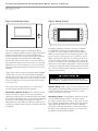
Figure 6: Remote Room Sensor
Figure 7: Remote Terminal
This wall-mountable display is an IP30 rated device.
Ambient conditions must be between 32.0ºF and 120.0ºF
and less than 85% RH. The controller’s RS485 serial
interface communicates via three-way plug-in terminals.
Use a twisted pair plus shielded cable, 20-22 AWG.
Total length of the network must not exceed 1,500 feet.
The capacitance between the wires must not exceed 90
pF/M. See your wiring schematic for connection details.
Note that undersized wiring will cause inaccurate sensor
readings.
Installing the Remote Terminal - The remote terminal
is an IP40 device and is powered through the cable
provided. If a longer length is required, a standard 24
AWG, 6 conductor phone cable may be used up to 150
feet. For location of the sensor up to 1,500 feet, use 22
AWG, 3 twisted pair cable. See your wiring schematic for
connection details. Pull the cord and connector through
the hole in the back of the mounting bracket. Attach the
bracket to the wall. After plugging the cord into the back
of the remote display, feed any extra wiring back into the
hole of the mounting bracket and gently snap the remote
display into the bracket.
These remote devices require a separate 24Vac 50/60HZ
1.5VA power connection. Provide a dedicated 250mAT
fuse for each sensor. Use a class 2 safety transformer with
a minimum rating of 4VA. If the sensor is wired to F1 and
F2 of the DOAS unit control panel terminal, G0 must be
connected to F2.
Do not run sensor wiring adjacent to, or in the same
conduit as wires carrying more than 24 VAC.
Mounting the Remote Terminal - The remote terminal
must be located in a dry, non-corrosive environment.
Operating conditions must be between 0.0ºF and 140.0ºF
and less than 90% RH. Moisture or chemicals can damage
the circuitry of the display. The display can either be
affixed directly to the DOAS unit (indoor models only) or
located up to 20 feet away using the cable that came with
the display.
26
CAUTION!
CAUTION! Do not run the remote terminal wiring in the
same conduit as, or adjacent to wires carrying over 30 volts!
Controls Wiring - Many of the controls and sensors in the
ClimateMaster Tranquility DOAS units have been factoryinstalled and wired. However, you will have to make
certain connections in the field.
Occupancy Contact - ClimateMaster makeup air DOAS
units as standard are pre-wired to work with a fieldprovided occupancy timer, switch, or dry contact closure
from a building management system, which will start the
supply blower during periods of occupancy. Whether
this switch is manually activated or a relay activated by a
building energy management system, its contacts must
be rated for at least 10 VA at 24 VAC.
C l i m a t e M a s t e r Wa t e r - S o u r c e H e a t P u m p s
THE SMART SOLUTION FOR ENERGY EFFICIENCY
Vertical DOAS
R e v. : 0 1 / 3 1 / 1 3
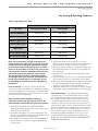
Unit Starting & Operating Conditions
Table 3: Operating Limits Table
VF/VD Models
Air Limits
Cooling/Dehumid Mode
Heating Mode
Minimum Ambient Air
40ºF [4.4ºC]
40ºF [4.4ºC]
Maximum Ambient Air
100ºF [37.8ºC]
100ºF [37.8ºC]
Minimum Entering Air
50ºF [10.0ºC]
15ºF [-9.4ºC]
Maximum Entering Air
110ºF [43ºC]
80ºF [26.7ºC]
Minimum Entering Water
35ºF [1.7ºC]
35ºF [1.7ºC]
Maximum Entering Water
105ºF [1.7ºC]
90ºF [32.2ºC]
Water Limits
Note: The manufacturer strongly recommends all
piping connections, both internal and external to the
unit, be pressure tested by an appropriate method
prior to any finishing of the interior space or before
access to all connections is limited. Test pressure may
not exceed the maximum allowable pressure for the
unit and all components within the water system.
The manufacturer will not be responsible or liable
for damages from water leaks due to inadequate or
lack of a pressurized leak test, or damages caused
by exceeding the maximum pressure rating during
installation.
Prior to Start-up - A complete startup will minimize
operational problems and expensive callbacks. Read this
section thoroughly before attempting to commission the
ClimateMaster DOAS unit. Always disconnect the power
before servicing the equipment!
Note: For information regarding the factorysupervised start-up with your system, refer to the
Service Bulletin towards the later part of this manual.
1. LEAK TEST ALL FIELD AND FACTORY PIPING.
Shipping and handling may have caused refrigerant
leaks inside the DOAS unit.
2. Check the rating plate for power requirements. The
available power supply voltage must be within ±5% of
the voltage printed on the rating plate.
3. Verify that all field wiring matches the ClimateMaster
wiring schematics. Inspect and tighten all field and
factory wiring.
4. Check and adjust the belt tension for a ½ -inch
deflection at the mid-point of the blower belt(s) when
approximately 5 pounds of pressure is applied.
5. Check the drain pan and the condensate piping. Test
the drain and prime the p-trap by pouring water into
the drain pan.
6. Verify that all service valves in the refrigeration lines
are fully open.
7. Inspect the air filters and coils to assure they are clean.
If necessary, clean the coils and install new air filters.
8. Purge any air, dirt, and debris from water lines (if used)
to avoid clogging the internal passages of optional
heating coils or water side heat exchangers.
9. Make sure that the unit is level and securely mounted so
that it cannot shift or transmit vibration to the building.
Start-up Procedure - First, read and understand the
“Start-Up Report” which was shipped with the DOAS
unit. ClimateMaster uses the start-up report to verify
the integrity of each installation. A thorough start-up
can reduce callbacks and can help increase customer
satisfaction. Carefully follow the process detailed in the
start-up report. Mail or fax the completed start-up report
back to ClimateMaster to validate your unit’s warranty.
Be sure to keep a copy for future reference. If you do not
have a start-up report, call the ClimateMaster Service
Department at (405) 745-6000 for a new copy. Please
be prepared with the model and serial number of the
DOAS unit. THE START-UP REPORT IS REQUIRED FOR
WARRANTY VALIDATION.
c l i m a t e m a s t e r. c o m
27
CLIMATEMASTER WATER-SOURCE HEAT PUMPS
Vertical DOAS
R e v. : 0 1 / 3 1 / 1 3
System Start-up Report - A copy of the system start up
report can be found in the back of this manual. This report
needs to be filled out thoroughly by a qualified service
technician and returned to ClimateMaster for warranty
validation. Please ensure that the model and serial
number of the unit is noted on this form. The model and
serial number can be found on the systems rating plate
located on or near the electrical compartment service
door. Failure to complete and return this form will void
the units warranty. These reports are also helpful when
trying to correct existing problems. Should you need
system diagnosis help, fax the completed worksheet to
the ClimateMaster Service Department using the number
provided. Be sure to include your name and a telephone
number where you can be reached.
Refrigeration System Operating Pressures - Many
factors affect the operating pressures on a given day. Such
factors include ambient temperature, air flow volume, and
relative humidity. The following ranges are typical:
Tranquility Models:
• HFC-410A Normal suction pressure range: 85 to
150 psig
• HFC-410A Normal discharge pressure range: 300
to 500 psig
Note: Always check the system air flow before you
troubleshoot the refrigeration circuit.
Start-up Supervision Supplemental Information
(Optional) - A ClimateMaster factory startup is required
to be purchased with the equipment. A factory startup
includes several key services:
• The expertise of an accomplished, factory-trained
mechanic who will supervise the commissioning of
the equipment.
• This ClimateMaster representative will assist the
installing contractor with filling out the Startup Report.
• He will also inspect the installation to make sure that
the DOAS unit has been properly integrated with the
rest of the equipment on the jobsite.
• Finally, he can train the maintenance personnel to
operate and service the equipment if necessary.
A factory start up does not include installation assistance.
The installing contractor is responsible for ensuring that
the system is ready for startup when the ClimateMaster
representative arrives.
When the installing contractor is confident the system
will be ready, he should contact the ClimateMaster Sales
representative to schedule the startup. Please call at
least two weeks before the desired startup date to help
prevent scheduling conflicts.
28
C l i m a t e M a s t e r Wa t e r - S o u r c e H e a t P u m p s
THE SMART SOLUTION FOR ENERGY EFFICIENCY
Vertical DOAS
R e v. : 0 1 / 3 1 / 1 3
System Operation Modes
Principle of Operation - Tranquility DOAS Units - The
Tranquility DOAS unit conditions 100% outdoor air. Its
refrigeration system extracts heat from, or rejects heat
into a building loop or geothermal loop to maintain
either the supply air or the space temperature. Its mode
of operation depends on whether the outdoor air is
above or below design conditions. A factory-installed
temperature sensor and a relative humidity sensor allow
the controller to dehumidify outdoor air if it is too humid
(usually above a 55°F dewpoint).
Humid Outdoor Air - When there is a demand for
outdoor air and the air is above the design setpoint,
the refrigeration circuit is activated. The multiple-row
evaporator removes excess moisture from the airstream.
A portion of the energy absorbed by the evaporating
refrigerant is directed to a reheat condenser inside of the
DOAS unit, which then reheats the dried airstream.
Dry Outdoor Air - When there is a demand for
outdoor air and that air is below the design setpoint,
the refrigeration circuit of the Tranquility is deactivated.
If the system is equipped with an auxiliary heating coil
(optional), it will turn on to heat the outdoor air to the
desired temperature.
The Tranquility DOAS will energize its compressors to
extract energy from a building loop or geothermal loop.
The system will divert this energy to
its hot gas reheat coil to heat the outdoor air to the
desired temperature.
Temperature Control Strategies - There are three
temperature control strategies available on the Tranquility
makeup air DOAS units. Those standard control
sequences include:
Controller Setpoints - To avoid ongoing controller
adjustments, adjust your setpoints accurately. It takes time
for the unit to establish equilibrium at a given setpoint.
Therefore, continued setpoint adjustments may lead to
higher energy consumption and user discomfort.
Leaving Air Temperature Control Option (LAT) Adjustments to the supply temperature can be made with
the user interface or over a DDC network. The controller
will send a signal to the auxiliary heater (where applicable)
to accurately maintain the supply air temperature during
the winter months. In the summer, when the mechanical
dehumidification is active, the controller maintains the
leaving air temperature by modulating the flow of hot
refrigerant to the hot gas reheat coil.
Tranquility systems equipped with this option are
provided with a supply air temperature sensor and a
duct-mounted sensor holder. See the holder cut sheet
for assembly and installation details. Mount the sensor at
least five feet downstream from the supply blower. Do not
mount the sensor where it can “see” the auxiliary heater,
since the radiation from the surface of the heater can
affect the sensor’s accuracy.
Room Reset of Leaving Air Temperature Control
Option (RRLAT) - In this sequence, the controller will
send a signal to the auxiliary heater (where applicable)
to accurately reset the supply air temperature based on
the deviation of the space temperature from its setpoint
during the winter months. In the summer, when the
mechanical dehumidification is active, the controller
resets the supply air temperature to meet the needs of
the space by modulating the flow of hot refrigerant to the
hot gas reheat coil.
• LAT Control – The temp sensor is mounted in the
supply duct. The DOAS unit will maintain a constant
supply air temperature setpoint.
• Room Reset of LAT – Temperature sensors are
mounted in both the conditioned space and the
supply duct. The unit will maintain a constant
discharge air temperature setpoint. However, the
LAT setpoint is automatically set higher or lower
depending on whether the conditioned space needs
heating or cooling.
• Unoccupied Temperature and/or Humidity Control
- A space mounted temperature and/or relative
humidity and damper box sensor is required. During
the unoccupied mode, the compressors will be cycled
on if space heating or cooling is required, or if the
space RH exceeds the setpoint.
c l i m a t e m a s t e r. c o m
29
CLIMATEMASTER WATER-SOURCE HEAT PUMPS
Vertical DOAS
R e v. : 0 1 / 3 1 / 1 3
Tranquility systems equipped with this option are
provided with a supply air and a room temperature
sensor, a wall-mounted sensor housing, and a ductmounted sensor holder. See the housing and holder cut
sheets for assembly and installation details. Mount the
space sensor in an area where its accuracy will not be
affected by drafts, hot spots, or solar gain. Mount the
supply air sensor at least five feet downstream from the
supply blower and auxiliary heater. Do not mount the
sensor where it can “see” the auxiliary heater, since the
radiation from the surface of the heater can affect the
sensor’s accuracy.
Unoccupied Temperature and/or Humidity
Control Option - This sequence is the standard control
strategy with the mixing box option and is the same
control strategy as Room Reset of LAT (described above)
in the occupied mode. The difference is the room sensor
is a temperature/humidity sensor which allows the DOAS
Unit to maintain an alternate space temperature and
humidity set point in the unoccupied mode. The outdoor
air temperature and humidity sensor do not affect unit
operation in this mode. The DOAS controller will output
signals in the unoccupied mode only for the following:
30
• Unoccupied Room Air Temperature Above 85° F
At this condition, the compressor will be activated and
divert all refrigerant to the condenser. This will cool
the space until the room temperature is 5°F below this
setpoint. The default setpoint is 85°F and is only fieldadjustable via optional remote display. However, it may
be factory-set to customer specifications.
• Unoccupied Room Air Temperature Below 55°F
At this condition, the controller will command full heat
to an auxiliary SCR-type electric heater. The controller
will activate the compressor and fully open the EEV
to divert hot gas refrigerant through the reheat coil.
Only when either of the two previously described
options is available, the space will be heated until the
room temperature is 5°F above this set point. The
default setpoint is 55°F and is only field-adjustable via
optional remote display. However, it may be factory-set
to customer specifications.
• Unoccupied Room Air Humidity above 65% RH
The DOAS controller will modulate refrigeration
components to maintain the room temperature at the
room temperature setpoint until the relative humidity
is 5% below this setpoint.
C l i m a t e M a s t e r Wa t e r - S o u r c e H e a t P u m p s
THE SMART SOLUTION FOR ENERGY EFFICIENCY
Vertical DOAS
R e v. : 0 1 / 3 1 / 1 3
Service and Maintenance
You can prevent many future problems by adhering to the
recommended maintenance schedule shown. If you do
discover a problem with the DOAS unit or the installation,
refer to the TROUBLESHOOTING GUIDE. IF YOU HAVE
EXHAUSTED THE TROUBLESHOOTING GUIDE AND
HAVE NOT DISCOVERED THE PROBLEM, CALL THE
CLIMATEMASTER SERVICE DEPARTMENT AT (405) 7456000. BE PREPARED WITH THE MODEL AND SERIAL
NUMBER OF YOUR DOAS UNIT.
Routine Maintenance - ClimateMaster DOAS units are
designed for years of reliable service. However, like any
piece of machinery they require periodic maintenance.
Service Monthly
• Check the air filters and replace them if necessary.
• Check the coils in the DOAS unit. Use compressed
air or a commercial coil cleanser if they are dirty or
plugged.
• Check the blower belts in the DOAS unit for wear,
glazing, and proper tension. Replace the belts if
necessary. Adjust the belts for approximately one
half-inch deflection at their midpoints.
If the compressor has failed because its motor has burned
out, the refrigerant, oil, and piping may have become
severely contaminated. If a burnout has occurred, use the
following procedure to replace the compressor and clean
the refrigerant system. YOU MUST CLEAN THE SYSTEM
THOROUGHLY TO PREVENT REPEATED COMPRESSOR
BURNOUTS! Use an oil test kit to determine the severity
of the burnout. Make sure you use rubber gloves and eye
protection, as contaminated refrigerant and oil can cause
severe burns!
Mild Burnouts - If the burnout is mild, recover the
refrigerant charge or transfer it to an unused portion of
the refrigeration circuit such as the receiver. You may need
to energize the liquid line solenoid valve to evacuate the
circuit completely. On systems equipped with an optional
tower water condenser, take care to avoid freezing the
condenser during evacuation.
If the compressor is equipped with rotolock valves, you
may want to install and evacuate the new compressor, and
use it to pump down the charge.
Notice! - Do not attempt this when a severe burnout
has occurred!
WARNING!
WARNING! Disconnect power before adjusting belts. Failure
to disconnect power could result in death or serious injury.
WARNING!
WARNING! Disconnect power before tightening terminals.
Failure to disconnect power could result in death or serious
injury.
Service Semi-Annually
• Tighten all field and factory electrical connections.
Mechanical vibration and thermal expansion can
loosen wires and terminals, which may lead to erratic
operation.
• Inspect and clean the condensate drain line(s) if
necessary. A clogged drain line can overflow and
cause extensive property and equipment damage.
Compressor Failure - Although some compressors fail
because they are mechanically flawed, most failures are
due to system-related problems. Compressor failure
can be caused by liquid floodback, air or moisture in the
refrigerant system, solid contaminants, excessive heat
or electrical service malfunctions. To avoid repeated
callbacks, you must determine the cause of the failure and
then correct it.
• Remove the old compressor.
• Install the new compressor. Be careful not to
overheat its pipe stubs if it is not equipped with
rotolock connections.
• Replace the suction filter with a suction line filterdrier. Sporlan Valve Corporation manufactures
special “HH” filter-dryers for cleaning system
burnouts. These filters are equipped with a tap for
measuring the pressure drop across the filter. If
you install a filter without a tap, solder a tap in the
suction line immediately upstream of the filter.
• Remove the old liquid line filter-drier and replace it
with a new “HH” type filter one size larger than the
original.
• Evacuate the system to purge the moisture and noncondensables from it. You may need to energize the
liquid line solenoid to evacuate all portions of the
refrigeration circuit.
Check the piping and joints for leaks, and recharge
the system.
c l i m a t e m a s t e r. c o m
31
CLIMATEMASTER WATER-SOURCE HEAT PUMPS
Vertical DOAS
R e v. : 0 1 / 3 1 / 1 3
Severe Burnouts
• If the burnout is severe, recover the refrigerant charge
or transfer it to an unused portion of the refrigeration
circuit such as the receiver. You may need to energize
the liquid line solenoid valve to evacuate the circuit
completely. On systems equipped with an optional
tower water condenser, take care to avoid freezing the
condenser during evacuation.
• Verify that the TXV and solenoid valves are not
plugged with debris. Clean or replace them if
necessary.
• Replace the suction filter with a suction line
filter-drier.
Sporlan Valve Corporation manufactures special “HH”
filter-driers for cleaning system burnouts. These filters
are equipped with a tap for measuring the pressure drop
across the filter. If you install a filter without a tap, solder
a tap in the suction line immediately upstream of the
filter.
• Remove the old liquid line filter-drier and replace it
with a new “HH” type filter one size larger than the
original.
• Remove the old compressor if you have not already
done so.
• Install the new compressor. Be careful not to overheat
its pipe stubs if it is not equipped with rotolock
connections.
• Evacuate the system to purge the moisture and noncondensables from it.
32
• Check the compressor contractor for damage or
pitted contacts. Some single-phase compressors are
equipped with start capacitors, run capacitors, and
starting delays. Check these components and replace
them if necessary.
• Check the piping and joints for leaks, and recharge the
system.
• Run the refrigeration system for an hour while you
monitor the pressure drop across the suction filter.
If the pressure drop is 3 psig or less after one hour,
continue to run the system for 24 hours, then take an
oil sample.
• If the oil sample is dirty or acidic, or if the one-hour
pressure drop is greater than 3 psi, then recover the
system charge and replace both the suction and liquid
filter-dryers. Repeat the previous step until your oil
sample tests negative.
C l i m a t e M a s t e r Wa t e r - S o u r c e H e a t P u m p s
THE SMART SOLUTION FOR ENERGY EFFICIENCY
Vertical DOAS
R e v. : 0 1 / 3 1 / 1 3
Troubleshooting
Supply Blower Will Not Run
Evaporator Coil Ices Up: Suction Pressure Below 85
psig (HFC-410A)
Possible Cause
Remedy
“Occupied switch in open position
Close “Occupied” switch
Loss of main power
Check for tripped circuit breaker
or blown fuse
Blower overload has tripped
Correct cause and reset overload
Faulty control wiring
Check for loose or incorrect wires
on system and controller
Compressor Will Not Run
Note: When there is a demand for outdoor air (the
“occupied” switch is on) and the outdoor air does not
need mechanical dehumidification, the compressor and
the refrigeration circuit of the unit will be locked out.
Possible Cause
Remedy
Loss of main power
Check for tripped circuit breaker
or blown fuses
Blower overload has tripped
Correct cause and reset overload
Faulty wiring
Check for loose or faulty wiring
on system and controller
Compressor overload has tripped
Correct cause and reset overload
Compressor failure may have
occurred if:
A: Compressor draws locked
rotor amps
B: Compressor starts but does
not pump
C: Motor windings have shorted
Compressor delay-timer
A: Replace compressor (or check
fuses on three-phase units)
B: Replace compressor
C: Replace compressor
Wait 3 minutes for timer
CAUTION!
CAUTION! Do not restart units without inspection and
remedy of faulting condition. Equipment damage may occur.
Possible Cause
Faulty or improperly set hot-gas
bypass valve
Insufficient evaporator air
flow rate
Remedy
1: Set hot-gas valve to maintain
30°F suction (55 psig)
2: Replace if defective
Assure air coil is clean and belts
are tight
Lack of refrigerant
Reevaluate system charge
Restricted refrigerant filter-drier
Evaluate filter pressure drop and
replace if necessary
Defective expansion valve
Evaluate expansion valve
performance and replace if
necessary
Restriction in refrigeration piping
1: Check coil for kinks in tubing
2: Check for debris in distributor
Liquid Line Solenoid
1: Check for 24 volts at the coil
2: Check to make sure solenoid
is tightly secured to the stem of
the valve
Head Pressure is Too High: Above 500 psig (HFC-410A)
Possible Cause
Remedy
Lack of adequate water flow
Install flow meter or circuit setter
to ensure correct flow rate
Excessive incoming water
temperature
If water temperature is above
90°F, consult factory for required
flow rates
Excessive air in condenser
water lines
Purge lines thoroughly or
install an air eliminator in the
system piping
A: Overload tripped (3-phase only)
B: Contactor faulty
C: Blower cycling on internal
overload (single phase only)
A: Reduce blower speed and
reset overlaod
B: Replace contactor
C: Reduce blower speed
Service valves closed or not
fully open
Fully open service valves
Non-condensables in
refrigeration system
Short-Term: Bleed noncondensables from high-point
purge points in system
Long-Term: Properly evacuate
and recharge refrigeration system
c l i m a t e m a s t e r. c o m
33
CLIMATEMASTER WATER-SOURCE HEAT PUMPS
Vertical DOAS
R e v. : 0 1 / 3 1 / 1 3
Appendix
Figure 9: System Rating Plate
Figure 10: Model Numbering Matrix
The system rating plate is attached to the outside of the
electrical box door. You will need rating plate information
when you install and service the DOAS unit.
34
C l i m a t e M a s t e r Wa t e r - S o u r c e H e a t P u m p s
THE SMART SOLUTION FOR ENERGY EFFICIENCY
Vertical DOAS
R e v. : 0 1 / 3 1 / 1 3
Service Bulletin
DEDICATED OUTDOOR AIR SYSTEM (DOAS)
Factory Pre-Commissioning Form, Pg. 1
Factory Commissioning of the DOAS system is required and is included in the sale of all DOAS units. Commissioning
requires a ClimateMaster Service Dept. Technician to visit the installation site and provide supervisory experience to installing/
commissioning contractor(s) as they perform the required procedures as outlined in our warranty activation commissioning report.
The company technician may also present an educational review of the DOAS unit operating and maintenance requirements. As
an option, and at the company’s discretion, a Certified Service Technician (CST) Commissioning may be performed. A CST
Commissioning is performed by a local Certified Service Technician who has been trained by the manufacturer. The CST will
perform all of the duties of the factory technician including commissioning supervision and maintenance and operation training.
To schedule a factory supervised commissioning this Pre-commissioning Form must be completed in its entirety and
returned to the ClimateMaster Technical Service Dept. Travel arrangements for commissioning will not be made until
Pre-commissioning forms are signed, returned to, and approved by the ClimateMaster Technical Service Dept. Allow
three (3) weeks for site visit scheduling.
The DOAS unit must be operable on the scheduled commissioning date. If, on the scheduled date, commissioning
cannot be completed and a return trip must be scheduled a Purchase Order for the second trip must be issued to
ClimateMaster. Delays and/or changes to a scheduled commissioning less than five (5) business days in advance may
result in additional charges. Commissioning delays on-site of more than 4 hours during commissioning may result in
additional charges.
The ClimateMaster Technical Service Dept. will advise contractors of their responsibilities and coordinate all site visits. The
responsible contractor will be advised if a factory technician or a CST will perform the commissioning.
The following list of items will apply to all DOAS unit commissioning and are the responsibility of the installing contractor.
In the event any of the following equipment cannot be furnished for the commissioning contact the ClimateMaster
Technical Service Dept. at (405) 745-6000 prior to signing/submitting this document.
Items required for commissioning:
Equipped service vehicle and qualified service technician.
Tech will be trained by factory tech/CST.
Refrigerant manifold gauges. (2-sets, R410A or R22
as needed)
Air balancing equipment (magnehelic or manometer
differential pressure gauge).
DMM and Amperage meters.
Digital thermometer with sensors.
50# of refrigerant (see unit type) & refrigerant scales.
Hand refrigerant oil pump.
Items to be completed prior to commissioning:
Open all access panels and inspect unit for concealed
shipping damage. Contact ClimateMaster immediately if
damage is noted. Do not repair damage without consulting
factory. Photograph all damage.
Leak check DOAS unit with a hand-held refrigerant leak
detector. Check and record refrigerant pressure of all
refrigerant circuits. Check and record ambient temperature
where unit is located.
Ensure DOAS unit is installed in accordance with IOM
requirements.
Condensate drain line with P-trap is installed.
All electrical terminations properly connected and tightened.
All field installed controls and sensors are installed and
properly connected. Field installed controls and sensors
include the user interface, S/A sensor, and possibly room
Temp/RH sensors.
Inspect all water lines for leaks and purge all air from DOAS
unit heat exchangers.
Verify water-piping connections are correct and leak free.
Verify water flow valve is installed and rated for correct GPM
flow rate. See unit labeling for GPM requirement and details.
Verify strainer (60 mesh or finer) is installed in supply water line.
Verify water temperature is within unit specifications.
A MINIMUM THREE (3) WEEK LEAD TIME IS REQUIRED TO SCHEDULE A DOAS UNIT COMMISSIONING.
Submit forms to: Attn: ClimateMaster Technical Service Dept. Fax (405) 745-6058
ClimateMaster 7300 S.W. 44th Street Oklahoma City, OK, 73179 (405) 745-6000
c l i m a t e m a s t e r. c o m
35
CLIMATEMASTER WATER-SOURCE HEAT PUMPS
Vertical DOAS
R e v. : 0 1 / 3 1 / 1 3
Pre-Commissioning Form, Pg. 2
Complete one (1) each this page for each DOAS unit
Unit Information
Model #
Serial #
Refrigerant pressure (standing): Circuit A
Circuit B
Ambient Temperature (degree F @ unit):
Contractor information
Company Name:
Address:
Contact Phone:
Fax:
Jobsite Information
Jobsite Address:
Contact Name:
Cell Ph:
Signature, Job Site Supervisor:
Date:
Water Test & Balance
Company Name:
T & B Technician Name (print):
Phone:
T & B Completion Date:
ClimateMaster Sales Representative
Company Name:
Contact/Salesman Name:
A MINIMUM THREE (3) WEEK LEAD TIME IS REQUIRED TO SCHEDULE A DOAS UNIT COMMISSIONING.
Submit forms to: Attn: ClimateMaster Technical Service Dept. Fax (405) 745-6058
ClimateMaster 7300 S.W. 44th Street Oklahoma City, OK, 73179 (405) 745-6000
36
C l i m a t e M a s t e r Wa t e r - S o u r c e H e a t P u m p s
THE SMART SOLUTION FOR ENERGY EFFICIENCY
Vertical DOAS
R e v. : 0 1 / 3 1 / 1 3
Start-Up Report
DEDICATED OUTDOOR AIR SYSTEM (DOAS)
Commissioning Report, Tranquility and Genesis Series Heat Pumps, Pg. 1
IMPORTANT: For warranty validation and activation a copy of this form must be completed for each
ClimateMaster DOAS unit and form must be returned to ClimateMaster Technical Service Dept.
immediately after completion of commissioning. Warranty shall not be considered valid or active
without verification from the ClimateMaster Technical Service Dept. For warranty status contact:
ClimateMaster Inc.
C/0 Service and Warranty Dept.
7300 S.W. 44th Street
Oklahoma City, OK, 73179
(405) 745-6000
INSTRUCTIONS
¾ Prior to Commissioning read and become familiar with the DOAS unit Installation and Operation
Manual (IOM) and the CM3500 Controller Application and Operation Manual (AOM). If you do not
fully understand the manuals or require additional information contact the ClimateMaster Technical
Service Dept. Be prepared to quote unit model number(s) and serial number(s).
¾ Use one (1) each Commissioning Report per unit. One report will be required for each DOAS unit.
Clearly print all required information. Additional comments or pages may be attached as needed.
WARNING!
ONLY TRAINED, QUALIFIED PERSONNEL SHOULD INSTALL AND/OR SERVICE CLIMATEMASTER
EQUIPMENT. SERIOUS INJURY, PROPERTY DAMAGE, AND/OR DEATH CAN RESULT FROM
IMPROPER INSTALLATION AND/OR SERVICE OF THIS EQUIPMENT. HIGH VOLTAGE ELECTRICAL
COMPONENTS, MOVING PARTS, AND HIGH REFRIGERANT PRESSURES ARE PRESENT.
Location and Unit Information
Job Name:
Installation Address:
ClimateMaster Sales Representative:
Unit Model #:
Serial #:
Form Completed by (print):
Signature:
Company Name:
Date:
Company Address:
Phone #:
Fax #:
c l i m a t e m a s t e r. c o m
37
CLIMATEMASTER WATER-SOURCE HEAT PUMPS
Vertical DOAS
R e v. : 0 1 / 3 1 / 1 3
Commissioning Report, Tranquility and Genesis Series Heat Pumps, Pg. 2
INSTALLATION CHECK LIST
Installation Manual Read
& Understood
DOAS Unit Properly Installed
Condensate Drain Installed,
Trapped, Primed
Verify Power Supply Matches Unit
Data Plate
Tighten/Check all Field & Factory
Wiring Connections
Check Blower Belt Tension
Check Blower rotation (3 ph Units Only)
Open ALL Manual Refrigerant Valves
POWER SUPPLY
Leak Check Unit With Hand-Held Leak
Check for Internal Damage
Leak Check Unit With Hand-Held Leak Detector
Verify Water Flow & GPM
Verify Air Filters Installed & Clean
BLOWER(S) OPERATION
Check with motors operating
Check voltage without motors operating
Supply Fan
L1-L2
Return Fan
L1-L2
L1-L2
L1-L3
L1-L3
L2-L3
L2-L3
L2-L3
Line Volt
L1
L1
L2
L2
L3
L3
Voltage @ Power Dist. Block
L1-L3
Voltage @ Main Transformer
Voltage @ Design Airflow
Amperage @ Design Airflow
Low Volt
WATER SYSTEM
Water Piping Size (O.D.)
Pressure Drop
Loop Type
PSI / ft
Antifreeze in Loop
Type / %
MWV Installed
Y/N
Strainer Installed
Y/N
AFR Installed
Y/N
Heat Tape Installed/Operable
Mesh Size
Y/N
Temperature and Relative Humidity
Space Temperature
Space Relative Humidity
ºF
Outdoor Air Temperature
ºF
%RH
Outdoor Air Temperature
%RH
Reheat Condenser Static Pressure
“wc
Enthalpy Wheel Supply Static Pressure
“wc
Supply Duct Static Pressure
“wc
Enthalpy Wheel Exhaust Static Pressure
“wc
Return Duct Static Pressure
“wc
Enthalpy Wheel Amps
Continued on Next Page
38
C l i m a t e M a s t e r Wa t e r - S o u r c e H e a t P u m p s
A
THE SMART SOLUTION FOR ENERGY EFFICIENCY
Vertical DOAS
R e v. : 0 1 / 3 1 / 1 3
Commissioning Report, Tranquility and Genesis Series Heat Pumps, Pg. 3
DOAS units have warm weather and cold weather modes of operation. Each mode MUST be tested and
documented for warranty Validation. For additional information contact ClimateMaster Technical Service
Dept. @ (800) 299-9747.
WARM WEATHER OPERATION (COOLING MODE)
Circuit A
Voltage @ Compressor Contactor
(Compressor Operating)
Compressor Amperage
Circuit B
T1-T2
T1-T2
T1-T2
T1-T2
T1-T3
T1-T3
T1-T3
T1-T3
T2-T3
T2-T3
T2-T3
T2-T3
L1
L1
L1
L1
L2
L2
L2
L2
L3
L3
L3
L3
Refrigerant Discharge Pressure
Psig
Psig
Refrigerant Liquid Line Temperature
ºF
ºF
Subcooling
ºF
ºF
Psig
Psig
Suction Temperature
ºF
ºF
Superheat
ºF
ºF
ºF
ºF
Refrigerant Suction Pressure
EWT
/
LWT
/
Td
COLD WEATHER OPERATION (HEATING MODE)
Circuit A
Voltage @ Compressor Contactor
(Compressor Operating)
Compressor Amperage
Circuit B
T1-T2
T1-T2
T1-T2
T1-T2
T1-T3
T1-T3
T1-T3
T1-T3
T2-T3
T2-T3
T2-T3
T2-T3
L1
L1
L1
L1
L2
L2
L2
L2
L3
L3
L3
L3
Refrigerant Discharge Pressure
Psig
Psig
Refrigerant Liquid Line Temperature
ºF
ºF
Subcooling
ºF
ºF
Psig
Psig
ºF
ºF
ºF
ºF
Refrigerant Suction Pressure
Suction Temperature
EWT
/
LWT
/
Td
c l i m a t e m a s t e r. c o m
39
CLIMATEMASTER WATER-SOURCE HEAT PUMPS
Vertical DOAS
R e v. : 0 1 / 3 1 / 1 3
$GGLWLRQDO&RPPHQWV
40
C l i m a t e M a s t e r Wa t e r - S o u r c e H e a t P u m p s
c l i m a t e m a s t e r. c o m
Rev.: 10/06
Please refer to the CM Installation, Operation and Maintenance Instruction for installation, operating and maintenance instructions.
LC395
*LC395*
NOTE: Some states or Canadian provinces do not allow limitations on how long an implied warranty lasts, or the limitation or exclusions of consequential or incidental damages, so the foregoing exclusions and limitations may
not apply to you. This warranty gives you speciÀc legal rights, and you may also have other rights which vary from state to state and from Canadian province to Canadian province.
Climate Master, Inc. • Customer Service • 7300 S.W. 44th Street • Oklahoma City, Oklahoma 73179 (405) 745 6000
OBTAINING WARRANTY PERFORMANCE
Normally, the contractor or service organization who installed the products will provide warranty performance for the owner. Should the installer be unavailable, contact any CM recognized dealer, contractor or service
organization. If assistance is required in obtaining warranty performance, write or call:
LIMITATION OF LIABILITY
CM shall have no liability for any damages if CM’s performance is delayed for any reason or is prevented to any extent by any event such as, but not limited to any war, civil unrest, government restrictions or restraints, strikes or
work stoppages, Àre, Áood, accident, shortages of transportation, fuel, material, or labor, acts of God or any other reason beyond the sole control of CM. CM EXPRESSLY DISCLAIMS AND EXCLUDES ANY LIABILITY FOR
CONSEQUENTIAL OR INCIDENTAL DAMAGE IN CONTRACT, FOR BREACH OF ANY EXPRESS OR IMPLIED WARRANTY, OR IN TORT, WHETHER FOR CM’s NEGLIGENCE OR AS STRICT LIABILITY.
LIMITATION OF REMEDIES
In the event of a breach of the Limited Express Warranty, CM will only be obligated at CM’s option to repair the failed part or unit or to furnish a new or rebuilt part or unit in exchange for the part or unit which has failed. If
after written notice to CM’s factory in Oklahoma City, Oklahoma of each defect, malfunction or other failure and a reasonable number of attempts by CM to correct the defect, malfunction or other failure and the remedy fails
of its essential purpose, CM shall refund the purchase price paid to CM in exchange for the return of the sold good(s). Said refund shall be the maximum liability of CM. THIS REMEDY IS THE SOLE AND EXCLUSIVE
REMEDY OF THE BUYER AGAINST CM FOR THE BREACH OF CONTRACT, FOR THE BREACH OF ANY WARRANTY OR FOR CM’S NEGLIGENCE OR IN STRICT LIABILITY.
Limitation: This Limited Express Warranty is given in lieu of all other warranties. If, notwithstanding the disclaimers contained herein, it is determined that other warranties exist, any such express warranty, including without
limitation any express warranties or any implied warranties of Àtness for particular purpose and merchantability shall be limited to the duration of the Limited Express Warranty.
CM is not responsible for: (1) The costs of any Áuids, refrigerant or other system components, or associated labor to repair or replace the same, which is incurred as a result of a defective part covered by CM’s Limited Express
Warranty; (2) The costs of labor, refrigerant, materials or service incurred in diagnosing the problem, removal of the defective part, or in obtaining and replacing the new or repaired part; or, (3) Transportation costs of the defective
part from the installation site to CM or of the return of any part not covered by CM’s Limited Express Warranty.
This warranty does not cover and does not apply to: (1) Air Àlters, fuses, refrigerant, Áuids, oil; (2) Products relocated after initial installation; (3) Any portion or component of any system that is not supplied by CM, regardless of
the cause of the failure of such portion or component; (4) Products on which the unit identiÀcation tags or labels have been removed or defaced; (5) Products on which payment to CM is or has been in default; (6) Products which
have defects or damage which result from improper installation, wiring, electrical imbalance characteristics or maintenance; or are caused by accident, misuse or abuse, Àre, Áood, alteration or misapplication of the product; (7)
Products which have defects or damage which result from a contaminated or corrosive air or liquid supply, operation at abnormal temperatures, or unauthorized opening of refrigerant circuit; (8) Mold, fungus or bacteria damages;
(9) Products subjected to corrosion or abrasion, including, without limitation, any corrosion due to improperly balanced pool chemistry or any other corrosive air quality; (10) Products manufactured or supplied by others; (11)
Products which have been subjected to misuse, negligence or accidents; (12) Products which have been installed and/or operated in a manner contrary to CM’s printed instructions; (13) Products which have defects, damage or
insufÀcient performance as a result of insufÀcient or incorrect system design or the improper application of CM’s products; (14) Products for which a START-UP REPORT has not been properly completed and timely returned to
CM; or (15) Products that may have been altered or repaired in any way outside of the factory in such a manner so as to affect, in CM’s sole judgment, the stability of functionality of the Product.
GRANT OF LIMITED EXPRESS WARRANTY
CM warrants only to its original purchaser all CM Tranquility OA (TO) Series and Genesis OA (GO) Series units purchased and retained in the United States of America and Canada to be free from defects in material and
workmanship under normal use and maintenance as follows: (1) All complete units built or sold by CM for twenty-four (24) months from date of shipment (from factory); (2) Repair and replacement parts, which are not supplied
under warranty, for ninety (90) days from date of shipment (from factory). All parts must be returned to CM’s factory in Oklahoma City, Oklahoma, freight prepaid, no later than sixty (60) days after the date of the failure of
the part; if CM determines the part to be defective and within CM’s Limited Express Warranty, CM shall, when such part has been either replaced or repaired, return such to a factory recognized dealer, contractor or service
organization, F.O.B. CM’s factory, Oklahoma City, Oklahoma, freight prepaid. The warranty on any part repaired or replaced under warranty expires at the end of the original warranty period. In order for this warranty to be valid,
a START-UP REPORT in the form contained in CM’s Installation, Operation and Maintenance Instructions (the “START-UP REPORT”) must be properly completed and timely returned to CM immediately after unit start-up, but
in no event later than one (1) week after unit start-up.
It is expressly understood that unless a statement is speciÀcally identiÀed as a warranty, statements made by Climate Master, Inc., a Delaware corporation, (“CM”) or its representatives, relating to CM’s products, whether oral,
written or contained in any sales literature, catalog or agreement, are not express warranties and do not form a part of the basis of the bargain, but are merely CM’s opinion or commendation of CM’s products.
EXCEPT AS SPECIFICALLY SET FORTH HEREIN, THERE IS NO EXPRESS WARRANTY AS TO ANY OF CM’S PRODUCTS. CM MAKES NO WARRANTY AGAINST LATENT DEFECTS. CM MAKES
NO WARRANTY OF MERCHANTABILITY OF THE GOODS OR OF THE FITNESS OF THE GOODS FOR ANY PARTICULAR PURPOSE.
CLIMATE MASTER, INC.
LIMITED EXPRESS WARRANTY/ LIMITATION OF REMEDIES AND LIABILITY FOR
TRANQUILITY OA (TO) SERIES AND GENESIS OA (GO) SERIES PRODUCTS
THE SMART SOLUTION FOR ENERGY EFFICIENCY
Vertical DOAS
R e v. : 0 1 / 3 1 / 1 3
Warranty
41
CLIMATEMASTER WATER-SOURCE HEAT PUMPS
Vertical DOAS
R e v. : 0 1 / 3 1 / 1 3
Notes:
42
C l i m a t e M a s t e r Wa t e r - S o u r c e H e a t P u m p s
THE SMART SOLUTION FOR ENERGY EFFICIENCY
Vertical DOAS
R e v. : 0 1 / 3 1 / 1 3
Notes:
c l i m a t e m a s t e r. c o m
43
CLIMATEMASTER WATER-SOURCE HEAT PUMPS
Vertical DOAS
R e v. : 0 1 / 3 1 / 1 3
Revision History
Date:
Item:
Action:
Decoder
TO VF/VD Physical Data Table
Updated
01/31/13
POE Oil Warning
Unit Connection and Services Clearances 4-15 Tons and 20-30 Tons
Added
Water Quality Table
Updated
03/21/11
Service Bulletin & Start-Up Report
Updated
01/03/11
Format - All Pages
Updated
07/26/10
Dimensional Data
Updated
06/11/10
Format - All Pages
Updated
GO (R22) Units
Removed
Decoder
Updated
12/23/08
Condensate Line Note
Updated
09/09/08
Pressure Testing Language
Updated
06/06/08
Duct System Installation, Water Quality Standards, Operating Conditions
Verbiage Updates
05/21/08
Pressure Testing Language
Added to Unit Starting and Operating Conditions
05/14/08
Physical Data
Inserted Physical Data Table
05/14/08
All Pages
Verbiage Updates
05/14/08
Wire Diagrams
Drawings Updated
01/01/07
First Published
R
AI
BR
I
HE
AT P U M P S
A
TO
NE
WATER
TO
IFIED TO ARI A
RT
S
C
CE
NG WITH
LYI
MP
O
IR
MANUFACT
UR
ER
06/11/10
02/06/09
IS
ST
AND
3
ARD 1
-1
R
O
25
6
7300 S.W. 44th Street
Oklahoma City, OK 73179
Phone: 405-745-6000
Fax: 405-745-6058
climatemaster.com
*87B0052N01*
97B0052N01
ClimateMaster works continually to improve its products. As a result, the design and specifications of each product at the time for order may be changed
without notice and may not be as described herein. Please contact ClimateMaster’s Customer Service Department at 1-405-745-6000 for specific
information on the current design and specifications. Statements and other information contained herein are not express warranties and do not form
the basis of any bargain between the parties, but are merely ClimateMaster’s opinion or commendation of its products.
ClimateMaster is a proud supporter of the Geothermal Exchange Organization - GEO. For more information visit geoexchange.org.
© ClimateMaster, Inc. 2006
44
C l i m a t e M a s t e r Wa t e r - S o u r c e H e a t P u m p s