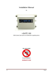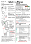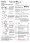
1
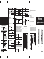
To add and delete users in card and PIN mode ( 3 1 # ) To Add a card and Pin user (The PIN is any four digits between 0000 ~ 9999 with the exception of 1234 which is reserved.) To change a PIN in card and PIN mode (Method 1) Note that this is done outside programming mode so the user can undertake this themselves To change a PIN in card and PIN mode (Method 2) Note that this is done outside programming mode so the user can undertake this themselves W1/W3-B Quick Reference Programming Guide To enter the programming mode To exit from the programming mode * Master code # 888888 is the default factory master code To delete a Card and PIN user just delete the card Add the card as for a card user Press * to exit from the programming mode Then allocate the card a PIN as follows: * Read Card 1234 # PIN # PIN # * Read Card Old PIN # New PIN # New PIN # To change the master code Enter the PIN then press # For a card user Read card For a card and PIN user Read card then enter PIN # Keypad Lockout 7 1 # Transmission Format: Alarm Output 7 2 # ◆ 1: Keypad Transmission The Reader will transmit the PIN data when it receives the last key (#) press after PIN code. To remove the alarm To reset the Door Forced Open warning To reset the Door Open Too Long warning Read valid card or Master Code # Close the door or Read vali d card or Master Code # To se t the facility co de Door relay time setting Door relay time setting 4 0~99 # The door relay time is between 0~99 seconds, the factory default setting is 5 seconds. * ID number# Old PIN # New PIN # New PIN # To set the facility code of W1/W3B (This operation might be required when W1/W3-B is acting as wiegand reader and connecting to 8 Facility code # Repeat Facility code # Facility Code can be any number between 1~255 (Default: 0) Format: Facility Code + PIN Code (Facility code is any digits between 0~255, factory default is 0; Pin code is any 1~4 digits between 0~9999) Example: Facility code: 1 PIN code: 5678 Press 5678 #, then the output format will be: 00105678 Format: Card Number (the last 8 digits of Card Number) Remarks: No matter the card or pin is valid or invalid, the data will be transmitted 2 User ID # 0 # ) The operating is the same as adding and deleting a card user in 3 2 # Door Open Too Long (DOTL) warning. When used with an optional magnetic contact or built-in magnetic contact of the lock, if the door is opened normally, but not closed after 1 minute, the inside buzzer will beep automatically to remind people to close the door and continue for 1 minute before switching off automatically. Door Forced Open warning. When used with an optional magnetic contact or built-in magnetic contact of the lock, if the door is forced open, or if the door is opened after 20 seconds of the electro-mechanical lock not closed properly, the inside buzzer and alarm output will both operate. The Alarm Output time is adjustable between 0-3 minutes with the default being 1 minute. 11 Interconnecting Two Devices 11.1 W1/W3-B operating as a Wiegand Output Reader In this mode the W1/W3-B supports a Wiegand 26 bit output so the Wiegand data lines can be connected to any controller which supports a Wiegand 26 bit input. See figure 1. To add a PIN user To add a card user User ID number # PIN # The ID number is any number between 1 ~ 2500. The PIN is any four digits between 0000 ~ 9999 with the exception of 1234 which is reserved. Users can be added continuously without exiting programming mode 1 Read Card # Cards can be added continuously without exiting from programming mode To delete All users To delete ALL users. Note that this is a dangerous option so use with care 6 0 # In this mode the W1/W3-B supports a Wiegand 26 bit input so an external Wiegand device with a 26 bit output can be connected to the Wiegand input terminals on the W1/W3-B. Either an ID card reader (125KHZ) or an IC card reader (13.56MHZ) can be connected to the W1/W3-B. Cards are required to be added at the external reader, except where an external EM reader is used, in this case cards can be added at either reader or controller. See figure 2. 6 2 GND V+ To add and delete card users by Manager cards To delete a PIN or a card user To delete card User by Manager Delete Card Manager add card Read card Manager add card Cards can be added continuously. Manager delete card Read Card Manager delete card Cards can be deleted continuously. To set the alarm output time (0~3 minutes) Factory default is 1 minute D0 White D1 # GND Green D0 To enable door open detection Special Power Supply DC 12 V /3A Pink Alarm output time To add card user by Manager Add Card Users can be deleted continuously without exiting from programming mode 2 0000 # To disable door open detection. (Factory default setting) D1 Grey ALARM- Yellow OPEN Brown 9 0~3 # Keypad Lockout & Alarm Output options. If there are 10 invalid cards or 10 incorrect PIN numbers in a 10 minute period either the keypad will lockout for 10 minutes or the alarm will operate for 10 minutes, depending on the option selected below. To Unlock the door D_IN Red V+ GND Power Controller AC&DC Black AC&DC Blue NO Purple COM Orange NC (With Wiegand 26 inPut) Normal status: No keypad lockout or alarm Present the card .7. Keypad/Reader/Controller 11.2 W1/W3-B operating as a Controller The master code is any 6 digits 1 Waterproof ◆ 2: Proximity Card Transmission The Reader will transmit the card data when it reads the Card. Door Open Detection No te that to un dertake the followi ng pr ogrammi ng the ma ster us er mus t be logged in To Add and Delete a card user For a PIN user 10.2 Door Relay, Door Open Detection, Alarm, Facility code Settings To add a card user in card only mode ( 3 * To unlock the door Pink GND Green D0 ALARM- Grey Exit button Brown D_IN AC&DC AC&DC D1 GND Yellow OPEN NC COM NO +12V GND OPEN D0 White D1 + Fail-Secure lock + Fail-Secure lock 2 3 4 5 6 7 8 9 0 # V+ + Door detecting switch - Alarm Red Black Blue NO COM NC Wiegand reader 1 Purple W1-B W3-B Orange W1/W3-B 7 0 # (Factory default setting) W1/W3-B User manual .8. .9. .10. 1. Packing list Name Quantity Remark l Built in buzzer l Red, Yellow and Green LEDs display the working status l 12~24V AC/DC l Two- year warranty 6. Wiring GND Colour Function Description Digital Keypad W1/W3-B 1 Green D0 Wiegand Output D0 User Manual 1 White D1 Wiegand Output D1 Grey Alarm - Alarm Negative Yellow OPEN Request to Exit Button D_IN Door Contact AC&DC 1 Rubber bungs 4 4. Specifications 6*27mm, used for fixing Self Tapping Screws 4 3.5*27mm, used for fixing Manager Card 2 Manager Add Card & Manager Delete Card Please ensure that all the above contents are correct. If any are missing please notify the supplier of the W1/W3-B. 2. Description Brown 12~24V AC/DC Operating Humidity 5%~ 95% RH Red 12~24V AC&DC 12~24V AC&DC Power Input 2500 Environment Conforms to IP68 Black 12~24V AC&DC 12~24V AC&DC Power Input 12 keys, 2 x 6 digits(W1-B) Adjustable Door Relay time 0~99 seconds Blue NO Relay NO 12 keys, 3 x 4 digits(W3-B) Adjustable Alarm Time 0~3 minutes Purple COM Relay COM EM 125 KHZ car d/ Tag Wiegand Interface Orange NC Relay NC Pink GND W1/W3-B Negative Keypad Card Type W1/W3-B is single door multifunction access controller or a Wiegand output keypad or card reader. It is suitable for mounting either indoor or outdoor in harsh environments. It is housed in a strong, sturdy and vandal proof Zinc Alloy electroplated case. The electronics are fully potted so the W1/W3-B is waterproof and conforms to IP68. The W1/W3-B supports up to 2500 users in either a Card, 4 digit PIN, or a Card + PIN option. The inbuilt card reader supports EM, 125KHZ frequency card/Tag. The W1/W3B has many extra features including block enrollment, wiegand 26 bits interface, and backlit keypad...etc. These features make the W1/W3-B an ideal choice for door access not only for small shops and domestic households but also for commercial and industrial applications such as factories, warehouses, laboratories, banks and prisons. Active Current <80mA Idle Current ≤40mA Lock Output Load Max 2A Alarm Output Load Max 20A Wiegand 26 input & output Electric Lock, Exit Button, Wiring Connections Dimensions Net Weight 550 g Gross Weight 700 g Connection Diagram GND .1. 8 9 0 ALARM- Black Exit from the programming mode Purple Orange Open the door Alarm Bright Bright - Bright - Bright - Buzzer Short Ring Short Ring Short Ring 3 Short Ring Short Ring Short Ring Short Ring NO NC Grey - Brown 7. To Reset to Factory Default J1 Door detecting switch Red Black To exit from the programming mode * Master code # 888888 is the default factory master code * To change the master code 0 New code # New code # The master code is any 6 digits. Setting the working mode: W3-B Purple 8. Anti Tamper Ala rm Orange Electric bo lt: NC Electric strike : NO PCB connect diagram .2. To add a card user (Method 1) This is a fast way to enter cards using ID number auto generation. 2 User ID number # Users can be deleted continuously without exiting programming mode * ID number # Old PIN # New PIN # New PIN # + - Lock Set valid card only users 3 0 # Entry is by Card only Set valid card and PIN users 3 1 # Entry is by Card and PIN together Set valid card or PIN users 3 2 # Entry is by either Card or PIN (default) The W1/W3-B uses a LDR (light dependent resistor) as an anti tamper alarm. If the keypad is removed from the cover then the tamper alarm will operate. 1 Read Card 1 ID number # Card # To ad d ca rd us er (Met ho d 3) Add a se ries ca rds us er s Bl ock Enr ol lment 5 ID number # 8 digits Card number # Card quantity # Ca rd quantity is betwe en 1~2 500. Th e 8 digits card numbe r is the last 8 digits on the card. Max imum 2500 cards can be enrolled at a stretch wi thin 3 mi nutes. To delete card user by card number. Note Users can be deleted continuously without exiting from programming mode. 2 Read Card To delete a card user by user ID. This option can be used when a user has lost their card 2 User ID Common Power Supply .3. .4. .5. # Cards can be added continuously without exiting programming mode To add a card user (Method 2) This is the second way to enter cards using User ID Allocation. In this method a User ID is allocated to a card. Only one user ID can be allocated to a single card. Remarks: Reset to factory default, the user's information is still retained. Blue W1/W3-B 10.1 User Settings To add and delete users in either card or PIN mode ( 3 2 # ) (Default setting) W1-B To Delete a PIN user 1 User ID number # PIN # The ID number is any number between 1 ~ 2500. The PIN is any four digits between 0000 ~ 9999 with the exception of 1234 which is reserved. Users can be added continuously without exiting from programming mode as follows: 1 User ID No 1 # PIN # User ID No 2 # PIN # To change the PIN of a PIN user No te tha t to un de rtake the fol lowi ng pr og rammi ng the mas ter us er mus t be log ge d in To reset to factory default, power off, press * , hold it and power on, release it until hear two beeps and the LED shines in orange, then read any two EM cards, the LED will turn in red, means reset to factory default setting successfully. Of the two EM cards read, the first one is Manager Add card, the second one is Manager Delete card. Pow er“+” Anti-demolition alarm To add a PIN users Alarm 10. W1/W3-B Deta iled Pro gra mming Guide Connect the negative pole of the lock to NC is for Fail safe lock. Connect the negative pole of the lock to NO is for Fail-secure lock. J1 # Operation failed Enter into programming mode In the programming mode Blue Exit button Yellow OPEN NC AC&DC COM OPEN D_IN AC&DC D0 D1 ALARM- GND D0 D1 OPEN D_IN NO NC AC&DC AC&DC ALARM- GND COM Alarm To enter the programming mode White D1 NO 6 + Power AC&DC 12~24V/3A Green D0 COM 4 - Notes: Power“+” AC&DC 7 Alarm“-” Pink AC&DC 5 Operation successful + Door detecting switch Red Blue Light - programming mode) D_IN 3 + Green Light Bright - (Note:This step must be done out of Alarm “-” l Remove the back cover from the keypad using the supplied security screwdriver l Drill 4 holes on the wall for the screws and I hole for the cable l Fix the back cover firmly on the wall with 4 flat head screws l Thread the cable through the cable hole l Attach the keypad to the back cover. 2 - Red Light Bright Bright Bright Special Power Supply Alarm 5. Installation 1 - Fail-secure lock Operation Status Power on Stand by Press keypad W 1/ W3-B L128 x W82 x H28 mm(W3-B) 3. Features l Waterproof, conforms to IP68 l Strong Zinc Alloy Electroplated anti-vandal case l Full programming from the keypad l 2500 users, supports Card, PIN, Card + PIN l Can be used as a stand alone keypad l Programmable one relay output l Backlight keypad l Wiegand 26 input & output l Adjustable Door Output time, Alarm time, Door Open time l Block enrollment, can enroll maximum 2500 consecutive card within 3 minutes l Very low power consumption (60Ma) l Fast operating speed, <20ms with 2500 users l Easy to install and program l Built in light dependent resistor (LDR) for anti tamper NC + Exit button COM NO +12V GND OPEN DOTL, External Alarm L135 x W58 x H26 mm(W1-B) Operating Temperature -25~60℃ COM Wiegand D1 Brown AC&DC NO Wiegand D0 White Yellow OPEN User Capacity Green Grey ALARM- Operating Voltage Card Reading Distance 3~6 cm ( W1-B&W3-B are in the same function, only different in shape. ) D-IN D1 In4004 Screw driver NC D0 9. Sound and Light indication Power DC 12 V /3A Pink .6. # # SELF INSTALL - NEED TECHNICAL ASSISTANCE? OPTION 1: DIRECT WITH THE SERVICE DESK – QUICKEST AND MOST EFFECTIVE METHOD Submit your enquiry direct with the service desk at – [email protected] The service desk has the most experienced staff in Australia to help with your problem but they need your help. Describe your problem in detail and as clearly as possible. Don’t forget to include a telephone number. Be certain to detail which model or models of you are working with. Send photos of the installation – they love photos. The people at the service desk are good but they are even better when they can see the installation. Send photos of the overall scene so they can see the entire installation. Also send photos of the wiring to the control board and any other part of the installation you think is relevant. Send video if appropriate. Smartphone’s these days take remarkably good video in small file sizes which can be emailed in a moment. If your problem needs a video to show the issue please feel free to send it. NOTE: THIS IS BY FAR THE FASTEST AND MOST SUCCESFUL WAY TO SOLVE YOUR PROBLEM PHOTOS AND VIDEOS ARE THE NEXT BEST THING TO BEING THERE OPTION 2: LODGE YOUR ENQUIRY LOCALLY - SLOWER BUT CAN STILL BE EFFECTIVE Make contact with the store of purchase. Branch staffs are typically not technicians and dependent on their length of service will have varying degrees of technical knowledge. If they cannot help however they will certainly either source help locally from their technicians or make contact with the service technicians on your behalf. OPTION 3: SERVICE CALL WITH AUTOMATIC SOLUTIONS TECHNICIAN – SLOWEST METHOD If you fall within the local branch service area it may be possible to book a local technician to look at your installation. Wait times will vary dependent on local workloads. The cost is a service fee which includes the first half hour and the hourly rate thereafter. If any Automatic Solutions provided parts are found to be defective and within warranty these will be provided free of charge. (NOTE: If you suspect that any parts are defective and within warranty you may wish to consider option 4) A note on this option: If you decide on this option you will be asked to sign an “authorisation to proceed” which will provide legal authority and payment security. This form has three options available of which only the first two are available to you. The third option is for warranty repairs only for full install customers. Self install customers requiring warranty only service need to refer to option four below. IMPORTANT: IN SHORT THIS OPTION WILL INCUR CHARGES OPTION 4: RETURN THE PRODUCT IF BELIEVED TO BE FAULTY As a self install customer who has purchased product if you believe the product to be faulty rather than an installation or site problem you have the option of returning the product for evaluation and to exercise your right to a replacement, repair or refund as applicable. All returned product is forwarded immediately to the service technicians for evaluation and response. There are two main methods available to return product – Direct to the service centre – this is the quickest method as it cuts out the branch delay Via the branch of purchase – slower because of the delay at the branch When choosing this option you need to complete a product return form. This form gives you all the information on procedure involved and where to send to. These are available at the branch of purchase, can be emailed to you (contact your branch), or available here - http://automaticsolutions.com.au/page/warranty.php