1
LI-2B Installation Manual
ARCO Pty. Ltd.
LI-2B Intelligent Gate Controller
Installation/Owners Manual
Please do not commence installation until you have read this instruction book.
LI-2B Installation Manual
Contents:
Introduction
Installation Options:
Standard Installation
Installation Procedure
Side Mount Installation
Restricted Side Room Installation
Out Swing Installation
Control Board & Settings:
Auto Close
Overloads
Anti-Clash leaf delay
Solar Wiring Detail
Options:
Push Button (PB)
Electric Lock (EL)
Photoelectric Safety (PE)
Troubleshooting
Trouble Shooting
LI-2B Installation Manual
Dear Installer/Owner
Congratulations on your purchase of the Australian Made Arco Pty. Ltd. Automatic Gate
Operator. The LI-2B gate operator is a breeze to install. It has been researched, designed
and manufactured by Arco Pty. Ltd. to be a reliable operator with almost non-existent
maintenance required.
To save you time and make installation easier, the LI-2B has a pre-wired control circuit
board and placed it under the cover with motor/gears etc. This means that you do not have
to spend time wiring up to a separate control box.
Circuitry for most options is already included. You simply have to connect up the external
devices. No extra boxes or cables are required.
The design features in the LI-2B gate operator will save you hours on site and the
installation will be neat and tidy.
Apart from the physical attributes the control circuit has some powerful operating features.
These can be adjusted on-site without modification to suit a range of situations.
This manual should answer most of your questions regarding the installation and operating
of the LI-2B gate operator. If further information is required, please contact us.
The Arco Pty. Ltd. LI-2B gate operator can be purchased as a single gate operator (primary),
which comes complete with the Logic Control Circuit board and can be installed on either
the left or right hand side. The dual set includes the above as well as a secondary (slave)
operator that does not have logic control.
LI-2B Installation Manual
Introduction
The Arco Pty. Ltd. LI-2B automatic gate operator is an electronically controlled automatic
gate operator for swing gates. The LI-2B has a range of features that are built in and some
options are also available.
The LI-2B intelligent Gate operator can be used in a variety of situations.
• 240 Volt AC or Solar Power or 12 Volt AC/DC
• Inward or Outward swinging gates
• Restricted Side Room
• Single gate or a gate pair
• Where a gate is required to swing 90 degree and up to 130 degrees
A powerful control system gives the flexibility to change some important characteristics of
the operation which include
• Automatic Close
• Sensitivity to obstacles
The control system also allows for the addition of the following options
• Electric Lock
• Photoelectric cells (240 volt only)
• Operation with a wide range of devices
For all its sophistication the LI-2B gate operator is extremely reliable and its robust
construction ensures a long trouble free life.
Arco Pty. Ltd. has extensively tested the LI-2B gate operator. It has undergone rigorous
factory load testing and has been passed as ready for site installation.
Please ensure that you read these instructions fully and any other instructions supplied
then simply follow the step-by-step instructions.
LI-2B Installation Manual
The LI-2B gate operators are suitable for gates that are correctly hinged and operate
smoothly and evenly both before and after the LI-2B gate operator is fitted.
The LI-2B gate operators are suitable for and guaranteed when the following conditions are
met.
The LI-2B gate drive system will drive a variety of gate styles, sizes and weights. Suitability
is dependant on the quality of hinging and the ongoing force required at ONE metre from the
hinge centre-point to open and close the gate. 15kg is the acceptable maximum for gates
opening IN (Pull) and 7.5kg for gates opening OUT (Push)
Do not connect to any 240-volt power, solar panel or battery if you do not understand any of
the instructions or have any doubts. Please call, fax or email us re your concerns BEFORE
you apply power to the unit or you may void your warranty.
DO NOT connect the RED spade terminal to the battery until you are ready to set the Limit
Switches. The RED spade terminal is supplied disabled* from the battery. (* i.e. Not
connected to the battery)
Important
• All power (240 volt/battery/solar panel) MUST be disconnected before moving Logic
Controller (circuit board) to change battery.
• Correct use of a SURFACE insecticide spray** is advised to deter insects from causing
damage to the electronics.
** To avoid loss of warranty – DO NOT SPRAY OR ALLOW ANY LIQUIDS ONTO ANY
ELECTRONIC CIRCUITRY.
LI-2B Installation Manual
Installation
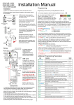
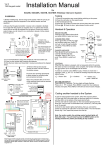
Standard Installation
A “Standard Installation” is one where the gate(s) open by swinging INWARDS towards the
motor housing.
The gate hinge should be no more than 200mm from the rear of the pier/post. Side room of
350mm is required to accommodate the swing of the arms.
Refer to Pages 10 & 11 if there is restricted side room (See figure 1)
Installation Procedure
1. Ensure that the gates swing freely and that all existing latches/pad-bolts/chains etc
are disabled or removed from the gate and gate posts.
2. When using a 240-volt unit, The Master operator (the one containing the circuit
board) should be fitted to the gatepost nearest the power supply. Remove the cover(s)
from the operator to access the slotted fixing holes in the rear of the chassis. Bend
the tabs out and bend them back against the rear of the chassis, in this position they
act as a spacer allowing clearance for the cover(s). NOTE: Do not remove these tabs –
just bend them out and fold them to the back unless you are using the OPTIONAL
mounting plate.
3. Position each unit on the gate-post{s} approximately 50mm from the edge of the
pier/post. The vertical position is found by locating the gate bracket. The gate
bracket is best placed where there is adequate fixing on the gate and movement of the
arms is unrestricted (See Figure 2). The gate operator may now be bolted in place.
LI-2B Installation Manual
LI-2B Installation Manual
4. If you have a pair of gates then connect the slave to the Master Unit with 2 core
Flex/Cable (Max load 8 Amp at 12 Volts) (See Figure 3). The LI-2B operators are set
in the factory for a “Standard Installation” with the Master placed on the LEFT HAND
SIDE (From the inside looking out). If the Master has to be located on the right then
the motor wires need to be reversed. To accomplish this, locate the connection blocks
for each motor on the Circuit Board. Swap the BROWN and BLUE wires for Motor 1
and Motor 2 (See Figure 3)
5. The gate bracket should be positioned so the arms are ALMOST in a straight line
when the gates are closed (See figure 4). To check the location of the gate brackets,
first disengage the Main arm from the drive shaft (using the spanner provided,
unscrew the bolt until the arm swings freely) THEN CLAMP THE GATE BRACKET IN
POSITION. Open and close the gate to ensure the gate bracket is appropriately
located.
LI-2B Installation Manual
6. Connect Power (12 volt or 24 volt or solar) to the Primary operator and connect the
battery
7. The Limit Switches may now be adjusted (See figure 5). Each of the Master and Slave
operators has its own pair of cams, one to set the open position and one to set the
closed position. Firstly mark the position of each cam as a reference. Loosen the
screw holding the cams. Operate the LI-2B operator with the transmitter and note
which cam controls opening and which cam operates the closing motion. (The cam
lobe activates a Limit Switch to turn off the motor). Reposition each cam and operate
the LI-2B again. Repeat until the gates open and close to the required positions.
8.
LI-2B Installation Manual
Side Mount Installation
The LI-2B operator may be mounted sideways with the long side against the pier/post for
extra flexibility.
This feature is very useful for situations where (Refer to figure 6)
• The gate must swing further than 90 degrees
• The gate swings outwards
• The gate swings outward and it is positioned at least 400mm forward of the back of
the pier/post
Note: See section on out swing installation.
Each LI-2B operator should be fitted to the pier/post with its output shaft close to the gate
hinge. With this in mind the “Standard Installation” instructions may now be followed.
Special covers are supplied to suit this type of installation.
LI-2B Installation Manual
Restricted Side Room Installation
This term is applied to the situation where the movement of the standard arms cannot be
accommodated within the side room available. In most situations this problem can be
overcome by cutting down the secondary arm. (The link joining the gate to the primary
arm).
This new length can be approximated by the following procedure.
1. Move the primary arm to a position suitable for the closed gate. Remembering that in
the closed position the primary and secondary arms must stop short of a straight-line
alignment (See Figure 7).
2. Mark a point on the gate suitable for the gate bracket.
Holding the gate bracket in position, measure the distance
between the hole centres on the gate bracket and primary
arm. Move the primary arm to its maximum open position.
Open the gate and measure the distance again. (See figure
8). If the length has changed then the gate bracket must be
repositioned and the same process repeated until the
dimensions remain the same for both positions. Be careful
that the secondary arm does not conflict with the drive
shaft of the primary arm.
3. Once the dimensions are consistent a new hole can be
drilled in the secondary arm and the arm trimmed to suit.
The gate bracket and secondary arm should now be fitted.
LI-2B Installation Manual
Out-Swing Installation
In this type of installation the gate swings outward away from the LI-2B operator to the open
position.
Several factors must be considered to determine the most suitable arm length.
include
• The drive through width required
•
The placement of the gate operator
•
The location of the gate on the pier/post
These
For assistance (if required) please provide a drawing (mud map) of your situation showing all
possible measurements.
Possible measurements include width between piers/posts, size of piers/posts, single or
double gates, position of hinges on piers/posts etc.
Note: The polarity of the motor connections may need to be reversed for out-swing
operation. See overload section.
LI-2B Installation Manual
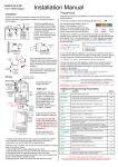
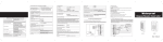
Settings
Auto Close
The operator control board is supplied with a “JUMPER” installed on a three-pin block. This
allows the gate to automatically close after a specific period. This period is adjustable.
(Refer to figure 9).
• Turn ‘Auto Close delay’ dial (Trimpot) Anti-clockwise to increase the hold open time
delay before gate closes automatically.
• Turn/dial trimpot clockwise to shorten the hold open time delay before gate closes
automatically.
Travel Time
There is a “Travel Timer” and a yellow LED and trimpot dial located to the left of the Auto
close Jumper. This should be set to approximately 5 to 10 seconds after full operation after
gate(s) reach full travel on limit switches in OPEN and CLOSED position (See figure 10).
Travel time can be adjusted by turning dial/trimpot Anti-clockwise to extend travel time and
vice-versa.
Green LED – Open Position (Located above relay 4)
Red LED – Close Position
This
•
•
•
“JUMPER” fits onto any two of three pins
If fitted on pins 1 and two the gate is set to close automatically.
If fitted on pins two and three the gate will require a signal to close
If there is no “JUMPER” or it is lost the gate will close automatically.
LI-2B Installation Manual
Multi-User Function
This function is for when the LI-2B gate operator is installed for multi-users (e.g. flats,
Apartments etc.) There is a Jumper installed on a three-pin block approximately in the
middle of the main control board. If the Jumper is on pins one and two the operator WILL
NOT allow the gate to close on a signal, it will continue to open position, time out then auto
close. If the Jumper is on pins two and three (Normal) a signal e.g. from the remote control
will reverse the direction of the operator.
Overloads
The overloads (See figure 9) are preset to maximum sensitivity, i.e. slight pressure will cause
the operator to STOP if it is opening or STOP & OPEN if it is closing.
Note: If these functions are reversed i.e. the gate STOPS when closing and STOPS and
REVERSES when opening then the polarity of the motor connections MUST be reversed and
the limit switch cams adjusted.
There is ONE overload for each gate as indicated on the main circuit board. To reduce the
sensitivity on the main circuit board turn the overload dials in the Anti-Clockwise direction.
BE CAREFUL large reductions in sensitivity may allow the gate(s) to exert excessive
pressure on people or vehicles trapped in the path of the gate(s).
Anti-Clash Leaf Delay for Pairs of Gates
To avoid jamming there is a time delay between the movements of each gate. This delay
may be independently adjusted for the Opening sequence and the Closing sequence.
Dial “R24” changes the closing delay and “R27” changed the opening delay.
In situations where the master operator is on the right hand side looking out, the “R24” sets
the Opening delay and “R27” sets the Closing delay.
Turning the dials/trimpots Anti-Clockwise gives the minimum delay.
LI-2B Installation Manual
Push-Button, Key –Pad etc.
A variety of hard-wired input devices can be used to operate the LI-2B operator.
should be in the form of a MOMENTARY CLOSED CIRCUIT.
Input
WARNING! Voltage must not be applied to these terminals. DAMAGE to the circuitry will
result if voltage is applied. Devices that send a Voltage Pulse (As some intercoms do) must
be connected to the circuit board through a relay.
Electric Lock
Connections for an electric lock/latch (EL) are provided on the circuit board. (See Figure 9)
This connection block will supply 12 Volts to energise the lock at the beginning of the
Opening and Closing cycles.
LI-2B Installation Manual
Photoelectric Safety Cell (240 volt & 12 volt operators only
A photoelectric safety cell (PE) may be fitted to detect obstructions in the path of the gate(s).
The PE will check for obstructions during the closing cycle only. If an obstruction is
encountered the gate(s) will reverse to the open position.
If the gate is set in the automatic close mode the gate(s) will remain open until the
obstruction is cleared.
Wires from the PE should be attached to the appropriate connection block. (See figure 9)
Note: Extra power consumption will occur when using Photoelectric Cells so extra panel(s)
and battery(s) will be required when gate(s) are operating on solar power only.
LI-2B Installation Manual
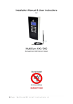
Solar Wiring Detail
Step 1
Locate two way terminal connection block on top plate near motor.
(Positive) and black (Negative) wires. Connect solar panel direct to it.
Red
Black
This will have Red
Brown or Red
+
Blue or Black
-
Solar
Panel
IMPORTANT
As a connected solar panel delivers a charge, the solar panel must be covered or
disconnected when any work or wiring is being done on the control board (other than when
adjusting trimpots or limit switches)
Step 2
Locate RED wire with spade terminal (Which will be disabled from Positive on Battery).
Connect this wire and you are ready to set your limits.
Negative Wire is already connected
Locate Positive Wire (RED)
Connect RED wire to + on battery
+
7.2 Amp
Hour
SLA
Batt
Red Wire to +
Note: All LI-2B gate operator kits (Solar, 240 volt and 12 volt) are supplied complete with a
7.2 Amp hour battery. This battery should be checked regularly.
LI-2B Installation Manual
Trouble Shooting
Poor range with the radio transmitter (Tx). Our standard transmitters are factory tested to
200 metres. 433Mhz Antenna is generally included to maximize signal to the radio receiver
(Rx). Poor range may occur for several reasons. The first two things to check are:
A. The Battery in the Tx
B. Antenna installation and wiring
Other causes is interference from other radio sources such as
•
•
•
Electric fences
Baby Monitors
Other local transmitters
Here the best solution is to remove the external source. If this is not possible the problem
may sometimes be solved by using special frequency transmitters and a matching radio
receiver (Rx). These are options that must be specifically ordered.
Other faults may be due to incorrect settings. Refer to “Settings” section of this manual to
ensure the settings are correct.
LI-2B Installation Manual
Specifications
Dimensions
Case:
245mm (H) x 140mm (W) x 335mm (D)
Primary Arm:
Pivot Centres 550mm
Secondary Arm: Pivot Centres 570mm
Weight
Master Unit including battery
Slave
21kg
17kg
Remote Control Systems
Arco can supply hand held transmitters and receiver boards. There are three models of
hand transmitters available – single, two and four button. The multi-button units allow
individual operation of several devices (gates, doors etc.) from one hand transmitter.
Where a system is already installed, on say the garage door, conversion kits can be fitted to
allow operation of the door and gates from one multi-button transmitter.
Power Requirements
Standard ……………………………………….240 Volts 50Hz AC
LI-2B Installation Manual
LI-2B Installation Manual
Auto
Reverse
Motor 1 & 2
c/wise =
less force
0.5A Fuse
Travel
Time LED
Battery
Negative
Positive
Auto Close
Anti-c/wise
to increase
hold open
time
Travel Time
c/wise =
minimum
Travel Time
DC In
Negative
Positive
Three Pin
Block
Jumper on
1&2=
Auto Close
Jumper on
2&3=
Manual
Close
10A Fuse
Motor 1
Open
Close
Close
Delay
Motor 2
Open
Close
Open
Delay
c/wise =
Maximum
Delay
Electric Lock
Negative
Positive
Photoelectric
Safety
Push
Button
Open
LED
Green
Close
LED
Red
SELF INSTALL - NEED TECHNICAL
ASSISTANCE?
OPTION 1: DIRECT WITH THE SERVICE DESK – QUICKEST AND MOST EFFECTIVE METHOD
Submit your enquiry direct with the service desk at – [email protected]
The service desk has the most experienced staff in Australia to help with your problem but they need your help.
Describe your problem in detail and as clearly as possible. Don’t forget to include a telephone number.
Be certain to detail which model or models of you are working with.
Send photos of the installation – they love photos. The people at the service desk are good but they are
even better when they can see the installation. Send photos of the overall scene so they can see the
entire installation. Also send photos of the wiring to the control board and any other part of the
installation you think is relevant.
Send video if appropriate. Smartphone’s these days take remarkably good video in small file sizes which
can be emailed in a moment. If your problem needs a video to show the issue please feel free to send it.
NOTE: THIS IS BY FAR THE FASTEST AND MOST SUCCESFUL WAY TO SOLVE YOUR PROBLEM
PHOTOS AND VIDEOS ARE THE NEXT BEST THING TO BEING THERE
OPTION 2: LODGE YOUR ENQUIRY LOCALLY - SLOWER BUT CAN STILL BE EFFECTIVE
Make contact with the store of purchase. Branch staffs are typically not technicians and dependent on their length
of service will have varying degrees of technical knowledge. If they cannot help however they will certainly either
source help locally from their technicians or make contact with the service technicians on your behalf.
OPTION 3: SERVICE CALL WITH AUTOMATIC SOLUTIONS TECHNICIAN – SLOWEST METHOD
If you fall within the local branch service area it may be possible to book a local technician to look at your
installation. Wait times will vary dependent on local workloads. The cost is a service fee which includes the first
half hour and the hourly rate thereafter. If any Automatic Solutions provided parts are found to be defective and
within warranty these will be provided free of charge.
(NOTE: If you suspect that any parts are defective and within warranty you may wish to consider option 4)
A note on this option: If you decide on this option you will be asked to sign an “authorisation to proceed” which
will provide legal authority and payment security. This form has three options available of which only the first two
are available to you. The third option is for warranty repairs only for full install customers. Self install customers
requiring warranty only service need to refer to option four below.
IMPORTANT: IN SHORT THIS OPTION WILL INCUR CHARGES
OPTION 4: RETURN THE PRODUCT IF BELIEVED TO BE FAULTY
As a self install customer who has purchased product if you believe the product to be faulty rather than an
installation or site problem you have the option of returning the product for evaluation and to exercise your right
to a replacement, repair or refund as applicable. All returned product is forwarded immediately to the service
technicians for evaluation and response. There are two main methods available to return product –
Direct to the service centre – this is the quickest method as it cuts out the branch delay
Via the branch of purchase – slower because of the delay at the branch
When choosing this option you need to complete a product return form. This form gives you all the information
on procedure involved and where to send to. These are available at the branch of purchase, can be emailed to
you (contact your branch), or available here - http://automaticsolutions.com.au/page/warranty.php