1
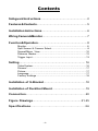
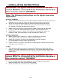
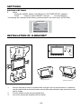
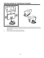
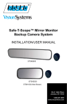
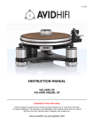
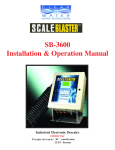
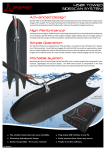
Safe-T-Scope™ 7” Waterproof
Rearview Backup
Camera System
INSTALLATION/USER’S MANUAL
STSK7360
90-21 144th Place
Jamaica, NY 11435
1.800.227.2095
www.roscovision.com
Contents
Safeguard Instructions........................................................ 2
Features & Contents............................................................. 5
Installation Instructions....................................................... 6
Wiring Camera & Monitor...................................................... 7
Function & Operation............................................................ 8
Monitor.........................................................................................8
Split Screen & Camera Select.....................................................8
Normal/Mirror View....................................................................10
Distance Marker.........................................................................12
Trigger Input...............................................................................13
Setting................................................................................ 16
Video System..............................................................................16
Dimmer....................................................................................17
Picture........................................................................................17
Language...................................................................................17
Factory Settings.........................................................................18
Installation of U-Bracket...................................................18
Installation of Duckfoot Mount.........................................19
Connection...................................................................20
Figure Drawings...........................................................21-25
Specifications..........................................................26
-1-
Safeguard Instructions
7”Waterproof Monitor
Please read the “Safety Rules“ carefully before using this product.
Following the safety rules prevents users from damages related with the
misuse of the product. It is very important to follow these safety rules.
We state “Caution“ and “Warning“ to clarify any potential risk for a
damage associated with the misuse of the product.
NOTICE
CAUTION
WARNING
This information is for user’s reference for better usability.
This information is for preventing damage.
This information is for preventing bodily harm.
User should follow safety rules.
CAUTION
Install all components while power is off.
- It may cause electronic shock or malfunction.
Do not connect the product directly to the battery, use switched ignition.
- It may cause battery discharge.
Do not use this product with multi socket or extended adaptor.
- It may cause unexpected heating, fire and malfunction.
When product is not in use for an extended period of time - unplug it.
- It may cause fire by short circuit due to heating.
Do not place near magnetic devices.
- It may cause malfunction and trouble.
Please ensure that the monitor is installed with enough room
for heat emission.
-2-
4
2
1
3
8
6
5
7
10
9
Controls
1. Automatic brightness control sensor
2. Dimmer
3. Mode
4. Up
5. Down
6. Left
7. Right
8. Menu
9. Power
10. Stand by lamp
11. Speaker (Waterproof)
-3-
11
Do not install product in direct sunlight, high temperature, or extremely humid areas.
- It may cause electronic shock or malfunction.
Please use this product within the voltage range specified.
- It may cause electronic shock or malfunction.
Do not place this product where air bag operation may occur..
- It may cause malfunction of air bag or injury due from bag hitting monitor.
Do not clean the exterior of the monitor using harsh abrasives or solvents.
- It may cause change of surface or malfunction.
Do not place this product in high vibration areas without appropriate mounting.
- It may cause damage or malfunction.
Do not drill or screw directly into body.
- It may cause electronic shock, fire and malfunction.
If the monitor is emitting smoke or a burning smell disconnect immediately.
- It may cause fire.
Do not disassemble, repair or remodel.
- It may cause malfunction and injury, void warranty.
When the power cable cord touches a metal case, cover it with a friction tape.
- Short circuit or disconnection of wire may cause a fire.
After finishing the installation, please check that the brake lamp, head lamp, and
wipers operate properly.
-4-
1
FEATURE
7”Waterproof Monitor
• Water Resistant (IP67), Aluminum housing
• 4 camera INPUT (NTSC/PAL)
• 2, 3, 4 Split Screen Function
• Dimmer sensor built in
• 7” WVGA (800 x 480) Wide LCD Panel
2
CONTENTS
7”Waterproof Monitor
• Before using this product, please check contents below. If there are
any missing parts please contact sales agent.
Monitor
Monitor Cable
Power Adaptor
Cable
Trigger Extension
Cable (x4)
Instruction
Manual
U-Bracket
Sun Visor
(Optional)
Duckfoot Mount
*Design & Specification are subject to change without notice.
-5-
INSTALLATION INSTRUCTIONS
IMPORTANT: For typical rear-view installation, the rear
camera MUST be connected to the distribution harness at
the connector marked “REVERSE”
Note: The following instructions are for typical rear-view
application.
STSC107 CAMERA
1. Attach camera bracket close to rear marker lights, centered on vehicle (see Fig. 1).
Attachment point must be sturdy enough to support camera and bracket.
2. We do not recommend mounting the camera near the lower area of the
vehicle (ex: bumper). This reduces the view of the camera and increases
the chance of physical damage to the camera.
3.
Attach camera to bracket using screws provided. Adjust angle as indicated
in Fig. 2. (Use rear bumper and back of vehicle as a reference point.)
4.
Wind deflector may be installed. This deflector is designed to reduce the
buildup of dust, dirt and moisture on the camera lens. (See Fig.3)
STSM207 MONITOR
1. Attach monitor inside vehicle in a location convenient to the driver
(ex: center of dash, overhead, or flush-mounted in dash).
2.
Attach the “duckfoot“ bracket to the dashboard or to the headliner
using self-tapping screws and/or adhesive pad.
3.
Fasten monitor to “duckfoot“ and adjust mounting angle to allow optimum driver
viewing comfort. (See Fig. 4.)
CABLE
1. The camera to cable connection is waterproof. Be sure to position the cable
properly. The male end attaches to the camera. The female end attaches to the
power/video/audio distribution harness, typically located under the dashboard.
(See Fig. 5.)
IMPORTANT: For typical rear-view installation, the rear
camera MUST be connected to the distribution harness at
the connector marked “REVERSE”
2.
Do not run the cable over sharp edges or corners. Do not kink the cable.
Keep the cable away from hot and rotating parts.
3.
Fasten all cable runs, and secure all excess cable.
-6-
WIRING CAMERA AND MONITOR
1.
Connect the red wire to an ignition switched accessory (ex: radio) power source,
and connect the black wire to chassis ground. See wiring diagram for connections
(See Fig. 5.)
2.
Before drilling, be sure no cable or wire is on the other side. Be sure to drill
a 20mm (0.8in) diameter hole only.
3.
Feed as much cable as possible into vehicle and clamp securely. This
reduces the possibility of it being hooked or snagged.
4.
Keep all cables away from HOT, ROTATING and ELECTRICALLY NOISY
components.
5.
Camera: Drill a 20mm (0.8in) diameter hole into vehicle body near the camera and
bracket. Insert camera cable into vehicle (be careful not to kink cable) and fit
grommet into hole. Apply sealant around grommet to increase resistance to water
penetration. Connect camera to the camera extension cable which runs inside
the vehicle.
6.
Monitor: The monitor terminates in a 13-pin connector, which should be connected
to the mating 13-pin receptacle end of the power/video/audio distribution harness.
7.
For typical rear-view installation, connect the camera extension cable
from the rear-view camera to the harness’s connector marked REVERSE.
8.
For multi-camera installations, be sure to mark each extension cable properly and
connect to the appropriate harness connector marked CA1 or CA2. Bundle excess
cable together using a cable tie or electrical tape.
9.
The green wire is the REVERSE trigger wire. In typical rear-view installations,
connecting this wire to the vehicle’s backup light circuit will activate the rear-view
image whenever the vehicle shifts into reverse.
10. FUEL TANKERS & OTHER SPECIALTY VEHICLES: All electrical equipment
fitted to petroleum vehicles must be connected via battery master switch and must
be isolated from the battery while the vehicle are loading and unloading. For other
specialty vehicles, please check applicable code and regulations prior
to installation.
11. Always consult your dealer when fitting any electrical or electronic equipment to a
vehicle fitted with a CAN-bus or multiplex system.
IMPORTANT : For installations requiring multiple cameras,
or for installations not requiring typical rear-view images,
please refer to the wiring diagram (Fig.5) and the particular vehicle’s electrical schematic for selection of proper
power and trigger connection points.
-7-
FUNCTIONS AND OPERATION
MONITOR
1. POWER
When the ignition is switched on, the monitor will be in standby mode (no image
will be on the screen), waiting for trigger signal.
When a trigger wire is energized by 12v power (such as backup lights turning on),
the image captured by the selected camera will appear on the monitor.
2.
Pressing the power switch will change the monitor status from standby to
steady-on. Steady-on mode status will show rear cameras view.
3.
VOLUME +/Adjust Speaker Volume
These buttons are also used to adjust the values within selected setting
of menu option
4.
MODE
Switching the screen mode.
Press MODE once
Full screen changes to 2 split screen.
Press Mode twice
2 slpit screen changes to 3 split screen.
Press Mode three times
3 split screen changes to 4 split screen.
Press Mode four times
4 split screen changes back to full screen.
SPLIT SCREEN & CAMERA FUNCTION
1. SPLIT SCREEN SWITCH
In the split screen, press
button to view the alternate split screen views
half view
1
tri view
1
quad view
1
half view
2
tri view
2
quad view
2
-8-
FUNCTIONS AND OPERATION - CONTINUED
2.
3.
CAMERA SELECTION
From the FULL SCREEN in the full screen, press the
CAM1 > CAM2 > CAM3 > CAM4 > CAM1 . . . .
button to see
CAM1
CAM2
CAM4
CAM4
Press the “Mode“ buttton to display the screen information (Input Mode/Volume)
CAMERA SELECTION FOR SPLIT SCREENS
In the 2 split screen press the “Mode“ button to see the OSD(On Screen Display).
While the OSD is on select with the
button the camera position
(Left or Right). Then press the
arrow to select the camera of choice.
SPLIT SCREEN SETUP
SPLIT SCREEN SETUP
CAM 1
SET LEFT
SET RIGHT
CAM 2
CAM 3
CAM 4
-9-
CAM2
FUNCTIONS AND OPERATION - CONTINUED
4.
CAMERA SELECTION FOR 3 SPLIT SCREENS
In the 3 split screen press the “Mode“ button to see the OSD(On Screen Display).
While the OSD is on, select with the
button the camera position
(Left, Top or Bottom). Then press the
button to select the camera of choice.
SPLIT SCREEN SETUP
SET LEFT
SET TOP
SET BOTTOM
5.
SPLIT SCREEN SETUP
CAM2
CAM 1
CAM 2
CAM 3
CAM 4
CAMERA SELECTION FOR 4 SPLIT SCREENS
In the 4 split screen press the “Mode“ button to see the OSD(On Screen Display).
While the OSD is on, select with the
button the camera position (Top Left,
Top Right. Bottom Left or Bottom Right). Then press the
arrow to select the
camera of choice.
SPLIT SCREEN SETUP
SPLIT SCREEN SETUP
SET LEFT
CAM 1
SET TOP
CAM 2
SET BOTTOM
CAM 3
CAM 4
CAM2
NORMAL/MIRROR VIEW
1.
CAM1 FULL SCREEN
From the CAM1 full screen press the “Mode” button. From the “MARKER SETUP”
screen press the “Mode” button again. Select the desired camera with the
then press
button to change Normal/Mirror view.
MIRROR SET
CAM1
MARKER SETUP
CAM1
MIRROR
ON
CAM2
MIRROR
OFF
CAM3
NORMAL
CAM4
MIRROR
- 10 -
FUNCTIONS AND OPERATION - CONTINUED
2.
CAM2 OR CAM3 FULL SCREEN
From the CAM2 or CAM3 full screen press the “Mode” button. From the
“CAM2 TRIGER SETUP” screen press the “Mode” button again. Select the
desired camera with the
then press
button to change
Normal/Mirror view.
MIRROR SET
CAM2
CAM2TRIGGER SETUP
3.
MIRROR
SPLIT SCREEN
CAM3
NORMAL
CAM4
MIRROR
CAM4 FULL SCREEN
From the CAM4 full screen press the “Mode” button. Select the
desired camera with the
then press
button to change
Normal/Mirror view.
MIRROR SET
CAM1
CAM1
MIRROR
CAM2
CAM4
4.
CAM1
FULL SCREEN
MIRROR
CAM2
MIRROR
CAM3
NORMAL
CAM4
MIRROR
SPLIT SCREENS (2/3/4)
From any multiple screen views press the “Mode” button. From the
“SPLIT SCREEN SETUP“ select a camera press the “Mode“ button again.
Select the desired camera with the
then press
button to change
Normal/Mirror view.
MIRROR SET
CAM2
SPLIT SCREEN SETUP
CAM1
MIRROR
SET LEFT
CAM2
MIRROR
SET RIGHT
CAM3
NORMAL
CAM4
MIRROR
- 11 -
FUNCTIONS AND OPERATION - CONTINUED
IMPORTANT
• The onscreen distance markers shold be considered as a general reference to
assist the driver in assessing the distances depicted on the screen. The distance
markers have been designed based on the “CCD camera installation conditions“
listed in the next section, but differences in vehicle design and construction may
result in the actual installation condition or location being different from the
conditions listed. In such cases, the display location should be set at the closest
marker No.
• The markers may not indicate the exact position of the bumper, the vehicle’s
width or the distance to the rear. USE AS REFERENCE ONLY.
DISTANCE MARKER
1.
ON SCREEN DISTANCE MARKER SETTING
In CAM1 full screen press the “Mode” button.
Select ON/OFF with
button and then press
button.
CAM4
MIRROR SET
ON
OFF
2.
MARKER SELECTION
Press “Mode” button four times & select MARKER SELECT menu.
Press
button, and switch marker pattern.
NOTE: Marker function only available when MARKER SETUP is on CAM1,
full screen mode.
CCD camera installation conditions
(distance marker input conditions)
Vehicle width
(Unit mm)
(From bumper toward rear) MARKER
SELECT
P1
Marker No
(Pattern)
7M
5M
3M
1M
Bumper position
- 12 -
Camera Install
Height
Vehicle
Width
P1
2.000
2.500
P2
2.250
2.300
P3
2.500
2.300
P4
2.750
2.300
P5
3.000
2.300
P6
3.250
2.300
P7
3.500
2.500
FUNCTIONS AND OPERATION - CONTINUED
3.
MARKER ADJUSTMENT (ADJUSTING THE BUMPER POSITION)
- Press “Mode“ button 5 times, select MARKER ADJUST from the menu.
- Press
button, select H/V. (H: horizontal, V: vertical)
- Press button, and switch marker patter.
( H= -10~ +10, V= -12~ +12, Default setting: H=0, V=0)
- After 10 seconds, set up screen disappears, and set up finishes.
* If there is no button operation, set up screen disappears even during set up process
TRIGGER INPUT
1.
SCREEN SWITCH WHILE TRIGGER INPUT
What is “Trigger Input“ or “Trigger Signal“? This is when a circuit send s signal to
the monitor showing connected camera on screen during driving mode.
(ex. if driver uses left/right turn signal or reverse gear.)
*Example below is set with TRG1(Rear light) = CAM1
TRG2(Left Signal) = CAM2
TRG3(Right Signal) = CAM3
TRG4(ETC.) = CAM4
- 13 -
FUNCTIONS AND OPERATION - CONTINUED
2.
CAM1
3.
If there is trigger input, the connected screen (Trigger input screen) is displayed as
full screen and the screen goes former one when the signal disappear.
CAM2
CAM4
In case of TRG2 and TRG3 input, by the OSD, the full or split screen could be
selected. If there is the TRG2(3) signal input, then CAM2(CAM3) and CAM1 split
screen are shown on the screen. With this function, Left (Right) and Rear side
could be checked.
CAM2
CAM2
CAM1
CAM2TRIGGER SETUP
FULL SCREEN
SPLIT SCREEN
In CAM2 full screen, press the “Mode” button to see OSD. Select split screen with
button and then press
button. If there is the left signal input (TRG2), then CAM2 (Left)
in left side and CAM1 (Rear) in right side will be shown on the screen.
CAM3
CAM1
CAM3
CAM3TRIGGER SETUP
FULL SCREEN
SPLIT SCREEN
In CAM3 full screen, press the “Mode” button to see OSD. Select split screen with
button and then press
button. If there is the left signal input (TRG3), then CAM1 (Rear)
in left side and CAM3 (Right) in right side will be shown on the screen.
4.
When there is the TRG1(Rear light) input, CAM1 video will be shown on the screen.
with
button, the 2 split screen CAM2/CAM1 or CAM1/CAM3 could be
displayed.
- 14 -
FUNCTIONS AND OPERATION - CONTINUED
5.
When there is the TRG1(Rear light) input, CAM1 video will be shown on the screen.
with
button, the 2 split screen CAM2/CAM1 or CAM1/CAM3 could be
displayed.
CAM2
CAM1
CAM1
CAM3
Button
CAM1
Button
6.
In case of light on emergency blinker (TRG2+TRG3), the monitor display CAM1~
CAM4 as quad split screen. And the screen goes former one when the signal
(light on emergency blinker) is disappeared.
CAM1
CAM2
CAM1
CAM4
CAM2
CAM3
The example is set with TRG1(Rear light)=CAM1 / TRG2(Left signal
light)=CAM2 / TRG3(Right signal light)=CAM3 / TRG4(etc)=CAM4.
- 15 -
FUNCTIONS AND OPERATION - CONTINUED
7.
When there is input signal more than 2 triggers, the monitor display fully connected
screen (Trigger input screen) as the priority order. And the screen goes former one
when the signal is disappears, the rest will be display as the priority order.
TRIGGER PRIORITY ORDER
TRG1(Rear light) > TRG2+3(Emergency light) > TRG2(Left side light)
> TRG3(Right side light) > TRG4
CAM1
CAM4
CAM1
CAM3
* If the screen turns by trigger signal, the POWER, MENU & MODE buttons
are disabled.
* In the standby position if the trigger wire is activated the monitor will turn on.
The screen will turn off once the power is de-activated to the trigger wire.
The screen will then turn off when the trigger signal has gone off.
SETTINGS_________________________________________________________
VIDEO SYSTEM
1.
NTSC/ PAL conversion
Press the “MODE“ button until OSD menu “PICTURE SETUP“ appears.
Press
button to select “VIDEO SYSTEM“ and use
to enter selection.
If using PAL system on NTSC system using county, it may cause a malfunction. The product
can convert NTSC / PAL system manually but it is not automatic. Before use, Please check
and set the system.
NTSC system country: USA, CANADA, JAPAN, KOREA, TAIWAN, MEXICO, etc.
PAL system country : AUSTRALIA, GERMANY, U.K., NETHERLANDS, ITALY, etc.
- 16 -
SETTINGS_________________________________________________________
DIMMER
2.
Dimmer sensor setting
Press the “MODE“ button until OSD menu “PICTURE SETUP“ appears.
Press
button to select “DIMMER“ and use
to enter selection.
Press the “DAY/NIGHT“ button to switch DAY >> NIGHT >> AUTO >> DAY
* Dimmer is set AUTO from the factory
PICTURE SETUP
DIMMER
CONTRAST 5
BRIGHTNESS 5
COLOR
TINT
LANGUAGE E
VIDEO SYSTEM
RESET
DAY
0
0
50
50
NGLISH
NTSC
>
PICTURE
3.
Picture setup
Press the “Mode“ button until OSD menu “PICTURE SETUP“ appears.
Press
button to select changes and use
to adjust value.
* Each factory setting is preset to 50.
PICTURE SETUP
DIMMER
CONTRAST 5
BRIGHTNESS 5
COLOR
TINT
LANGUAGE E
VIDEO SYSTEM
RESET
DAY
0
0
50
50
NGLISH
NTSC
>
LANGUAGE
4.
Language display selection
Press the “Mode“ button until OSD menu “PICTURE SETUP“ appears.
Press
button to select changes and use
to adjust value.
* Language selection: ENGLISH - FRENCH - GERMAN - ITALIAN - SPANISH
PICTURE SETUP
DIMMER
CONTRAST 5
BRIGHTNESS 5
COLOR
TINT
LANGUAGE E
VIDEO SYSTEM
RESET
DAY
0
0
50
50
NGLISH
NTSC
>
- 17 -
SETTINGS_________________________________________________________
FACTORY SETTINGS
5.
Reset
Press the “MODE“ button until OSD menu “PICTURE SETUP“ appears.
Press
button to select “RESET“ and use
to enter selection.
* All settings are initialized at the factory mode except for the video input. (NTSC/PAL)
PICTURE SETUP
DIMMER
CONTRAST 5
BRIGHTNESS 5
COLOR
TINT
LANGUAGE E
VIDEO SYSTEM
RESET
DAY
0
0
50
50
NGLISH
NTSC
>
INSTALLATION OF U-BRACKET_______________________________
Double side adhesive tape
Screw hole
Double side
adhesive tape
Ceiling Installation
1.
2.
3.
Standard Installation
Ensure that the monitor is installed with enough room for heat emission. Install the
monitor stand with enclosed screws and double side adhesive tape as shown in the
above image.
Fix the monitor to the monitor stand firmly.
Sun Visor should be installed with 4 screws.
- 18 -
INSTALLATION OF DUCKFOOT MOUNT__________________
Double side
adhesive tape
Double side
adhesive tape
1.
2.
3.
Ensure that the monitor is installed with enough room for heat emission. Install the
monitor stand with enclosed screws and double side adhesive tape as shown in the
above image.
Fix the monitor to the monitor stand firmly.
Sun Visor should be installed with 3 screws.
- 19 -
Mini-din A type
- 20 -
DCM-051A
MDM-094A
CAM4
CAM 3
CAM 2
CAM 1
GRAY (CAM4)
ORANGE (CAM 3)
GREEN (CAM 2)
BLACK (CAM 1)
DC IN
CONNECTION
Fig. 1
Camera mount in
suggested location
Mount camera assembly high.
(Centered)
Camera mounting hole pattern
- 21 -
Fig. 2
Position of camera
Vehicles behind truck
Street
Rear Bumper
Typical monitor image of view from properly installed camera
- 22 -
Fig. 3
Optional wind deflector
- 23 -
Fig. 4
Mounting on ceiling
Mounting on the dash, console etc.
- 24 -
Fig. 5
POWER INPUT LEAD (RED) To
Ignition Switched Accessory
GROUND WIRE (BLACK) To metal
point of the vehicle
CA2 Trigger 2
(WHITE)
CAM 2
REVERSE Trigger 1
(GREEN)
Note: For typical single camera installation,
this trigger wire should be connected to the
vehicle’s “back up lights” circuit, and the
rear-view camera should be attached to the
connector marked “REVERSE”
- 25 -
SPECIFICATIONS
STSC107 CAMERA
PICK-UP DEVICE TV SYSTEM PICTURE ELEMENTS SENSING AREA IMAGE SIZE SYNCHRONIZATION HORIZONTAL RESOLUTION REQUIRED ILLUMINATION SIGNAL TO NOISE RATIO POWER SUPPLY POWER CONSUMPTION CURRENT CONSUMPTION LENS ANGLE OPERATION TEMPERATURE STORAGE TEMPERATURE WEIGHT DIMENSIONS (W x H x D) STSM207 MONITOR
INTERLINE TRANSFER TYPE CCD
PAL/NTSC
512(H) x 582(V) PAL
512(H) x 492(V) NTSC
0.2x0.1in (4.9mm x 3.7mm)
1/4 inch
INTERNAL
420 TV LINES
0 LUX MINIMUM/F1.2
MINIMUM 48dB(AT AGC OFF)
12Vdc
3.5W(AT 12Vdc)
MAX. 200mA
120º(D), 88º(H),66º(V)
-15ºF to +160ºF
-20ºF to +176ºF
0.6Kg (0.41lb)
3 x 2 x 2in (75 x 48 x 49mm)
SCREEN 5.0 inch (127mm)
DEFLECTION ANGLE POWER CONSUMPTION POWER SOURCE TV SYSTEM VIDEO INPUT/OUTPUT COLOR TFT-LCD
50°(LEFT/RIGHT), 15°(TOP), 35°(DOWN)
8W/700mA MAXIMUM
12-30Vdc
PAL/NTSC
COMPOSITE VIDEO SINGLE
1VP-P 75 OHM
RESOLUTION CONTRAST BRIGHTNESS VIEWING ANGLE (U x D x R/L) OPERATING TEMPERATURE STORAGE TEMPERATURE WEIGHT OUTER DIMENSIONS (W x H x D) 960(H) x 234(V)
350:1
400cd/m2
15 x 30 x 50
-5°F to +150°F
-13°F to +158°F
0.4Kg (0.80lb)
5.7 x 4.3 x1in (144 x 110 x 25mm)
(without flush mount)
DISCLAIMER
The use of the STSK7360 Vehicle CCTV system should not in any way be used
as a substitute for careful and cautious driving. Always obey traffic laws and motor
safety regulations must always be adhered to.
Specifications subject to change without any notice.
- 26 -
90-21 144th Place
Jamaica, NY 11435
www.roscovision.com
Ph. 1.800.227.2095
A Century of
Automotive Safety
Fx. 1.718.297.0323
Printed in China
Lit. P/N: 04242012