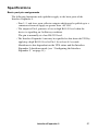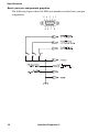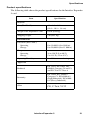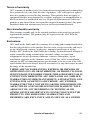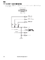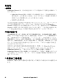
1
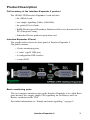
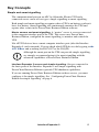
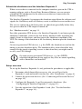
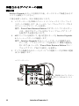
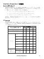
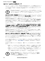
User’s Guide Interface Expander 2 AP9624 This manual is available in English on the APC Web site (www.apc.com). 本マニュアルの日本語版は APC ウェブサイト (www.apc.com) から ダウンロードできます。 anual finns tillgänglig på svenska på medföljande CD. Contents Introduction . . . . . . . . . . . . . . . . . . . . . . . . . . . . . . . . . . . . . . 1 Overview ...........................................................................1 Features of the Interface Expander 2 ..................................1 Hardware requirements .....................................................2 Choosing Cables ................................................................2 Safety warning ..................................................................2 Product Description . . . . . . . . . . . . . . . . . . . . . . . . . . . . . . . . 3 Full inventory of the Interface Expander 2 product .............3 Interface Expander 2 Panel .................................................3 Basic monitoring ports .......................................................3 Configuration DIP switches ................................................4 Status LED ..........................................................................4 Type B USB port .................................................................4 Key Concepts . . . . . . . . . . . . . . . . . . . . . . . . . . . . . . . . . . . . . 5 Simple and smart signalling ................................................5 Configuring PowerChute Business Edition for simple signalling ....................................................................................6 Low Battery signal ..............................................................6 Scheduled shutdowns and the Interface Expander 2 ..........7 Setup overview ..................................................................7 Installation . . . . . . . . . . . . . . . . . . . . . . . . . . . . . . . . . . . . . . . 8 Installation procedure ........................................................8 Connecting to Protected Devices . . . . . . . . . . . . . . . . . . . . . . 10 Connection procedure .....................................................10 Configuring the Interface Expander 2 . . . . . . . . . . . . . . . . . . 11 Shutdown modes .............................................................11 DIP Switches ....................................................................11 Confirmed shutdown mode .............................................12 Until Low Battery shutdown mode ..................................13 i Contents continued Timer shutdown mode .....................................................13 Test the Interface Expander 2 ...........................................14 Troubleshooting . . . . . . . . . . . . . . . . . . . . . . . . . . . . . . . . . . 15 If you have problems with your Interface Expander 2 card... .........................................................................................15 Specifications . . . . . . . . . . . . . . . . . . . . . . . . . . . . . . . . . . . . 17 Basic port pin assignments ...............................................17 Basic port pin assignment graphics ..................................18 Product specifications .......................................................19 Life-Support Policy . . . . . . . . . . . . . . . . . . . . . . . . . . . . . . . . 20 Two-Year Factory Warranty . . . . . . . . . . . . . . . . . . . . . . . . . . 20 Disclaimer . . . . . . . . . . . . . . . . . . . . . . . . . . . . . . . . . . . . . . . 23 ii Introduction Overview The UPS Interface Expander 2 (AP9624) from APC by Schneider Electric provides two additional computer interface ports for a UPS equipped with a SmartSlot™ accessory slot. This enables the UPS and your power management software to provide a graceful system shutdown for up to three network servers or other devices during an extended power outage. The Interface Expander 2 draws power from the UPS in order to monitor the UPS and report power conditions such as on-battery and low battery events whether the UPS is receiving AC utility power or not. Features of the Interface Expander 2 The Interface Expander 2 card: • Mounts in all supported APC by Schneider Electric devices equipped with a SmartSlot accessory slot. • Works well in a heterogeneous network. Servers running different operating systems can monitor the same UPS simultaneously. • Typically supports smart signalling on the serial port of the UPS. • Can delay shutdown of the UPS until all servers have shut down gracefully. • Has operating modes that cause the UPS to shut down after confirmation from all protected devices or after an interval set by the user. See “Configuring the Interface Expander 2” on page 11. • Does not depend on the operation of the network to protect connected devices. As a hard-wired accessory, the Interface Expander 2 reliably conveys important status messages during poor power conditions. Interface Expander 2 1 Introduction Hardware requirements The Interface Expander 2 works with most APC by Schneider Electric UPS devices with a SmartSlot and an output rated less than or equal to 30kVA. See the full list online by going to the APC KBase page and searching for FA176135 as the FAQ ID. Choosing Cables The table below lists the cables for use with the systems supported by the Interface Expander 2. When ordering a cable, provide the Part Number. IF you want to connect the Interface Expander 2 to a… Windows server THEN use or order… Part Number 940-0020 cables (included) UNIX basic Signalling UNIX server Cable AP9823 10 or 15-ft extension cable UPS Interface Extension AP9815 25 or 50-ft extension cable Isolated Extension Cable AP9825 Safety warning The Interface Expander 2 must be used only in conjunction with a UPS and monitoring cables from APC by Schneider Electric. Using a UPS or cable made by any other manufacturer may cause damage or improper operation. Do not connect a computer to any Interface Expander 2 port using a “straight-through” wired extending cable. Do not operate the Interface Expander 2 where the ambient temperature or humidity is outside the limits listed in “Product specifications” on page 19. 2 Interface Expander 2 Product Description Full inventory of the Interface Expander 2 product The AP9624 UPS Interface Expander 2 card includes: • the AP9624 card, • two simple signalling Cables (940-0020), • the printed User's Guide, • RoHS (Restriction of Hazardous Substances Directive) document for the EU (European Union), • Schneider Electric product registration card. Interface Expander 2 Panel The graphic below shows the front panel of Interface Expander 2. The panel contains: • 2 basic monitoring ports, • a “mini” type B USB port, • 4 configuration DIP switches, • a status LED. Basic monitoring ports The two computer interface ports on the Interface Expander 2 are called Basic ports because they supply simple UPS signalling for On Battery and Low Battery conditions in the UPS. For further information see “Simple and smart signalling,” on page 5. Interface Expander 2 3 Product Description Configuration DIP switches The Interface Expander 2 configuration DIP switches control the shutdown operation of the unit. See “Configuring the Interface Expander 2” on page 11. Status LED The Interface Expander 2 card status LED provides important information concerning operation of the unit. Refer to the table below for a description of the conditions indicated by the LED. Status Description SOLID GREEN Indicates communications and operations are fine. FLASHING GREEN Indicates that the Expander 2 card is initializing. FLASHING RED Indicates that the Expander 2 card is unable to establish or maintain communications with the UPS. The UPS might not be supported by the Expander 2 card or the card might need a firmware update in order to support this UPS. SOLID RED Indicates the UPS is not supported by the Expander 2 card or the card might need a firmware update in order to support this UPS. Type B USB port The “mini” type B USB port is for performing firmware upgrades only. 4 Interface Expander 2 Key Concepts Simple and smart signalling The communication between an APC by Schneider Electric UPS and a connected server can be of two types: simple signalling or smart signalling. Both simple and smart signalling recognize when a UPS is on battery or when it has a low battery. Smart signalling also continuously monitors the UPS and reports other events in the PowerChute Business Edition software. Master servers and smart signalling. A “master” server is a server connected to the computer interface port of the UPS. This server uses PowerChute Business Edition, configured for smart signalling, to monitor and control the UPS. Not all UPS devices have a smart computer interface port (after the Interface Expander 2 card is inserted). You can check which UPS devices do by going to the APC KBase and searching for FA176957 as the FAQ ID. Although the smart port on the UPS can provide simple signalling, we strongly recommend using it for smart signalling with the advanced capabilities of PowerChute Business Edition. Interface Expander 2 servers and simple signalling. Servers connected to the basic ports of the Interface Expander 2 use simple signalling with PowerChute Business Edition to provide UPS shutdown capabilities. If you are running PowerChute Business Edition on these servers, you must configure it for simple signalling. See “Configuring PowerChute Business Edition for simple signalling” on page 6. Interface Expander 2 5 Key Concepts Configuring PowerChute Business Edition for simple signalling To use PowerChute Business Edition (PowerChute) on a server connected to the Interface Expander 2, configure PowerChute for simple signalling. This procedures pertains to v9.1 and higher of PowerChute. For previous versions, see your PowerChute documentation. 1. Install or re-install PowerChute. 2. When the installation program prompts for the UPS Type, select “Interface Expander Basic Port” and continue with the installation. 3. Run PowerChute and connect to the UPS. 4. Verify that the status line on the PowerChute Console or the PowerChute Agent screen shows “On Line.” Low Battery signal The Interface Expander 2 generates a low battery signal when it detects a low battery condition at the UPS. It can also generate a low battery signal under certain other conditions according to the configured shutdown mode (see “Configuring the Interface Expander 2” on page 11), when it may force a low battery signal and an on battery signal, causing the servers to shut down. 6 Interface Expander 2 Key Concepts Scheduled shutdowns and the Interface Expander 2 When a server that is connected to the computer interface port on the UPS is running software such as PowerChute Business Edition, you can execute scheduled UPS shutdowns for the other servers that are connected to the Interface Expander 2. The Interface Expander 2 recognizes the shutdown signal from the software and signals the On Battery and Low Battery events to attached servers and devices. The servers connected to the basic ports are shut down gracefully before they lose power when the UPS output is turned off. See “Shutdown modes” on page 11. For older generation UPS devices, the Interface Expander 2 card intercepts the shutdown commands, waits for the low battery duration while signalling the simple clients to shut down, and then passes the shutdown command to the UPS. The timing of the shutdown is the low battery duration plus the shutdown delay. On newer generation UPS devices, e.g. the SMX, the shutdown occurs but the timing is just the shutdown delay. The shutdown delay alone should be long enough for the simple signalling servers to shut down but you might want to review your UPS settings. On some newer generation UPS devices, e.g. the SURTD, scheduled shutdowns do not apply as they have no smart signalling with a SmartSlot card installed. Setup overview To set up the Interface Expander 2 card, perform the procedures as applicable: 1. Determine which SmartSlot accessory slot you will use for the Expander 2 card and install it in that slot. (See “Installation” on page 8). 2. Connect the protected devices. (See “Connecting to Protected Devices” on page 10). 3. Configure the Expander 2 card for automatic shutdown. (See “Configuring the Interface Expander 2” on page 11). 4. Test the operation of the Expander 2 card. (See “Test the Interface Expander 2” on page 14.) Interface Expander 2 7 Installation Warning: Handle the Interface Expander 2 by the front panel. Do not touch the exposed printed circuit board or components. Touching them might result in damage to the Interface Expander 2. Installation procedure If your UPS configuration uses more than one SmartSlot device, see the online manual addendum called “Installing Multiple Management Cards” on the APC website, available under many SmartSlot accessories including the Interface Expander 2. To install the Interface Expander 2, perform the following steps. 1. Unpack the Interface Expander 2. The shipping materials are recyclable. Please reuse or dispose of them appropriately. 2. Before you install the Interface Expander 2 card, install any required power management software (PowerChute Business Edition). 3. The Interface Expander 2 card can be inserted/ plugged in at any time but consult your UPS documentation for the correct accessory card installation procedure. 4. Orient the Interface Expander 2 to fit the accessory slot. 5. Slide the Interface Expander 2 all the way into the slot until the front panel is flush with the back panel of the UPS or device. Note: While it is not possible to install the Interface Expander 2 upside down, it is possible to damage the unit in the attempt to do so. Observe the correct orientation as shown on the following page. The sides of the printed circuit board align with the card guides in the sides of the accessory slot. The accessory slot in the UPS or device may be oriented horizontally or vertically. 8 Interface Expander 2 Installation 6. Secure the Interface Expander 2 with the screws that you removed at step 3. 7. Proceed with “Connecting to Protected Devices” on page 10. Interface Expander 2 9 Connecting to Protected Devices Connection procedure After you have installed the Interface Expander 2 card, you should proceed with connecting the devices to be protected by the card. Refer to the graphic below while performing the following steps. 1. Connect the master server to the smart computer interface port of the UPS. (See “Master servers and smart signalling” on page 5.) Note: A server not supported by PowerChute Business Edition must use simple signalling with the appropriate cable. 2. Connect any other servers to the basic ports on the Interface Expander 2, using APC cables. Note: Servers connected to the basic ports of the Interface Expander 2 use simple signalling for monitoring the UPS, see “Configuring PowerChute Business Edition for simple signalling” on page 6. 3. Connect the power cords of all protected servers and devices to the power outlets on the UPS. Status Basic Por t 1 OK Config 1 23 4 0 1 COM ERROR FAULT Basic Por t 2 USB AP9624 UPS Interface Expander 2 Figure 1:Connecting the 10 Interface Expander 2 Configuring the Interface Expander 2 Shutdown modes Configure the Interface Expander 2 using one of the three available modes of automatic UPS shutdown. (Select a mode using the “DIP Switches” ). • “Confirmed shutdown mode” on page 12 • “Until Low Battery shutdown mode” on page 13 • “Timer shutdown mode” on page 13 After configuration, you should “Test the Interface Expander 2” on page 14. DIP Switches Select the shutdown mode by using the DIP switches as described in the following table. (An abbreviated form of this table also appears on the bottom side of the Interface Expander 2 circuit board.) Switch Setting (↓ =0, ↑ =1) Shutdown Mode 1 2 3 4 Confirmed 0 0 0 * Until Low Battery 0 0 1 N/A 2 min. 0 1 0 N/A 5 min. 0 1 1 N/A 10 min. 1 0 0 N/A 15 min. 1 0 1 N/A 30 min. 1 1 0 N/A 60 min. 1 1 1 N/A Await Confirmation 0 0 0 0 Treat as Confirmed 0 0 0 1 Timer * Server on UPS port Interface Expander 2 11 Configuring the Interface Expander 2 Confirmed shutdown mode In Confirmed mode, the Interface Expander 2 card shuts down the UPS after all connected servers have signalled that they have completed shutdown of the operating system. If any server that is connected to either a) an Interface Expander 2 basic port, or b) the UPS port, is not capable of sending a shutdown confirmation signal, do NOT use Confirmed mode. Behavior of Confirmed mode. If power returns before any connected server has signalled shutdown of the operating system, the Interface Expander 2 card returns to On Line status. If the Expander 2 card detects a Low Battery condition in the UPS before all connected servers have signalled shutdown of the operating system, it notifies the servers that the UPS battery is exhausted, and shuts down the UPS after the Low Battery signal time has elapsed. If AC utility power returns after at least one server has confirmed shutdown of the operating system — but before all servers have confirmed system shutdown — the Expander 2 card forces On Battery and Low Battery signals so that the remaining servers shut down as well. The Expander 2 card sends the forced Low Battery signal for a period of time equal to the Low Battery signal time and then shuts down the UPS, which cycles power to restart the servers. Confirmed shutdown mode and the UPS port. If you configure the Interface Expander 2 card in Confirmed shutdown mode by setting DIP switches 1, 2, and 3 in the down (0) position, you must set DIP switch #4 to determine the behavior of the server or device connected to the UPS port. For most newer generation UPS devices, DIP switch #4 should be in the 1 (up) position. For further details, see FA176957 as the FAQ ID in the APC KBase. For older generation UPS devices, DIP switch #4 behaves as follows: • With DIP switch #4 in the 0 (down) position, the UPS port operates normally, awaiting shutdown confirmation in the Confirmed mode. • With DIP switch #4 in the 1 (up) position, the Expander 2 card treats the UPS port as always confirmed. Use this setting when the UPS port will not be receiving a shutdown confirmation signal. When the shutdown mode of the Expander 2 card is set to Until Low Battery or Timer, the position of DIP switch #4 has no effect. 12 Interface Expander 2 Configuring the Interface Expander 2 Until Low Battery shutdown mode Until Low Battery shutdown mode is similar to the standard operation of the UPS. During an AC utility outage, the Interface Expander 2 card allows the UPS to run on battery until utility power is restored, or until the battery is exhausted. If the Expander 2 card detects a UPS Low Battery condition, it sends a Low Battery signal on all ports for a period of time equal to the Low Battery signal time and then it shuts down the UPS. If AC utility power returns after the Low Battery timer has begun, the Expander 2 card will continue the countdown and force the UPS to cycle power. This mode is useful for applications which require maximum run time. Timer shutdown mode In Timer shutdown mode, the Interface Expander 2 card enables the UPS to operate on battery for a user-specified length of time before shutting down the UPS. See “DIP Switches” on page 11 for the available timer settings. If power returns before the timer has run out, the Expander 2 card returns to On Line status. When the timer runs out or when the Expander 2 card detects a Low Battery condition in the UPS, the card sends a Low Battery signal for a period of time equal to the Low battery signal time and then shuts down the UPS. Interface Expander 2 13 Configuring the Interface Expander 2 Test the Interface Expander 2 To check the operation of the Interface Expander 2 card, perform the following steps in the order given. 1. Confirm that the UPS is on and that the battery is fully charged. 2. Verify that the Expander 2 card has been installed, connected, and configured. 3. Confirm that all connected servers and devices are on and running their power management software with power management screens visible, if applicable. 4. Confirm that the status LED on the Expander 2 card is on, indicating normal operation. 5. Simulate an AC utility power failure. 6. Confirm that all connected servers and devices have received the On Battery message from the Expander 2 card by refreshing the view on PowerChute Business Edition or your power management software. 7. Restore utility power. 8. Confirm that all connected servers and devices have received the message that utility power has been restored by refreshing the view on PowerChute Business Edition or your power management software. Note: To check the shutdown mode of your configuration, keep the utility power off long enough to allow all connected servers and devices to shut down. After all connected servers and devices have shut down, restore power and verify that they all restart. 14 Interface Expander 2 Troubleshooting If you have problems with your Interface Expander 2 card... The troubleshooting chart below covers many of the problems that might arise with the Interface Expander 2 card. If you encounter a problem, refer to this troubleshooting chart first. There may be a simple solution you are overlooking. Problem A server connected to a basic port does not acknowledge On Battery signal. Status LED flashes red continuously. Possible Cause Solution The software screen has not been refreshed. Refresh the power management software screen. The wrong cable is being used. See “Choosing Cables” on page 2. There is an internal problem with the Expander 2 card. Remove the Expander 2 card temporarily from the UPS and reinstall. This indicates a communication fault between the Expander 2 card and your UPS. Verify that your UPS is supported (“Hardware requirements” on page 2). Try re-inserting the Expander 2 card. Contact “APC Worldwide Customer Care Center” on page 26 Interface Expander 2 15 Troubleshooting Problem One or more servers shuts down when the UPS is on battery, but does not restart when power returns. Possible Cause Solution Timer mode: the operating system shutdown time is too short. The power management software shutdown time, if configured, must be set longer than the Expander 2 card Timer shutdown mode setting. Confirmed mode: the Expander 2 card did not receive shutdown confirmation from servers that shut down, and utility power was restored. Verify that the servers can confirm shutdown. If not, configure the Expander 2 card for Timer or Until Low Battery shutdown mode. The server shut down but the UPS did not shut down. The server on the UPS port cannot communicate with the UPS. The communication cable is not properly connected. Verify cable connections. See “Choosing Cables” on page 2. The wrong cable is being used. Verify that the cable is correct for this server. The master server is connected to the Expander 2 card. The master server must be connected to the computer interface port on the UPS. The port on the master server is being used by another application. Close the offending application. The port on this type of UPS does not support smart signalling with the Expander 2 card. Check the FA176957 article as the FAQ ID in the APC KBase. Contact “APC Worldwide Customer Care Center” on page 26. 16 Interface Expander 2 Specifications Basic port pin assignments The following limitations and capabilities apply to the basic ports of the Interface Expander 2: • Pins 3, 5, and 6 are open collector outputs which must be pulled up to a common referenced supply no greater than +40 VDC. • The output at Pin 2 generates a low-to-high RS-232 level when the device is signalling an On Battery condition. The pin is normally at a low RS-232 level. • The Interface Expander 2 unit may be signalled to shut down the UPS by applying a high RS-232 level to Pin 1 for at least 4.5 seconds. Shutdown is also dependent on the UPS status and the Interface Expander 2 shutdown mode (see “Configuring the Interface Expander 2,” on page 11). Interface Expander 2 17 Specifications Basic port pin assignment graphics The following figures show the DB9 port numbers and the basic port pin assignments. Figure 2: port pin assignments 18 Interface Expander 2 Specifications Product specifications The following table shows the product specifications for the Interface Expander 2 card. Item Specification Size (H × W × D): 4.0 × 4.0 × 1.5 in (10.2 × 10.2 × 3.8 cm) Weight of the Expander 2 card: 0.2 lb (0.09 kg) Shipping weight: 1 lb (0.45 kg) Physical Environmental Elevation (above MSL): Operating Storage 0 to 10,000 ft (0 to 3000 m) 0 to 50,000 ft (0 to 15 000 m) Temperature: Operating Storage 32 to 104°F (0 to 40°C) 5 to 113°F (-15 to 45°C) Operating Humidity: 0 to 95%, non-condensing Approvals Radiated EN 55011, EN 55022, IEC 62040-2 Category C2 and C3, and FCC Part 15 Class A Immunity EN 55024, IEC 62040-2 Category C3, EN 61000-6-1 (Light Industrial), EN 610006-2 (Heavy Industrial). Other CE, C-Tick, VCCI Interface Expander 2 19 Life-Support Policy General policy Schneider Electric does not recommend the use of any of its products in the following situations: • In life-support applications where failure or malfunction of the Schneider Electric product can be reasonably expected to cause failure of the lifesupport device or to affect significantly its safety or effectiveness. • In direct patient care. Schneider Electric will not knowingly sell its products for use in such applications unless it receives in writing assurances satisfactory to Schneider Electric that (a) the risks of injury or damage have been minimized, (b) the customer assumes all such risks, and (c) the liability of Schneider Electric is adequately protected under the circumstances. Examples of life-support devices The term life-support device includes but is not limited to neonatal oxygen analyzers, nerve stimulators (whether used for anesthesia, pain relief, or other purposes), autotransfusion devices, blood pumps, defibrillators, arrhythmia detectors and alarms, pacemakers, hemodialysis systems, peritoneal dialysis systems, neonatal ventilator incubators, ventilators (for adults and infants), anesthesia ventilators, infusion pumps, and any other devices designated as “critical” by the U.S. FDA. Hospital-grade wiring devices and leakage current protection may be ordered as options on many Schneider Electric UPS systems. Schneider Electric does not claim that units with these modifications are certified or listed as hospital-grade by Schneider Electric or any other organization. Therefore these units do not meet the requirements for use in direct patient care. Two-Year Factory Warranty This warranty applies only to the products you purchase for your use in accordance with this manual. 20 Interface Expander 2 Terms of warranty APC warrants its products to be free from defects in materials and workmanship for a period of two years from the date of purchase. APC will repair or replace defective products covered by this warranty. This warranty does not apply to equipment that has been damaged by accident, negligence or misapplication or has been altered or modified in any way. Repair or replacement of a defective product or part thereof does not extend the original warranty period. Any parts furnished under this warranty may be new or factory-remanufactured. Non-transferable warranty This warranty extends only to the original purchaser who must have properly registered the product. The product may be registered at the APC Web site, www.apc.com. Exclusions APC shall not be liable under the warranty if its testing and examination disclose that the alleged defect in the product does not exist or was caused by end user’s or any third person’s misuse, negligence, improper installation or testing. Further, APC shall not be liable under the warranty for unauthorized attempts to repair or modify wrong or inadequate electrical voltage or connection, inappropriate on-site operation conditions, corrosive atmosphere, repair, installation, exposure to the elements, Acts of God, fire, theft, or installation contrary to APC recommendations or specifications or in any event if the APC serial number has been altered, defaced, or removed, or any other cause beyond the range of the intended use. THERE ARE NO WARRANTIES, EXPRESS OR IMPLIED, BY OPERATION OF LAW OR OTHERWISE, OF PRODUCTS SOLD, SERVICED OR FURNISHED UNDER THIS AGREEMENT OR IN CONNECTION HEREWITH. APC DISCLAIMS ALL IMPLIED WARRANTIES OF MERCHANTABILITY, SATISFACTION AND FITNESS FOR A PARTICULAR PURPOSE. APC EXPRESS WARRANTIES WILL NOT BE ENLARGED, DIMINISHED, OR AFFECTED BY AND NO OBLIGATION OR LIABILITY WILL ARISE OUT OF, APC RENDERING OF TECHNICAL OR OTHER ADVICE OR SERVICE IN CONNECTION WITH THE PRODUCTS. THE FOREGOING WARRANTIES AND REMEDIES ARE EXCLUSIVE AND IN LIEU OF ALL OTHER Interface Expander 2 21 Two-Year Factory Warranty WARRANTIES AND REMEDIES. THE WARRANTIES SET FORTH ABOVE CONSTITUTE APC’S SOLE LIABILITY AND PURCHASER’S EXCLUSIVE REMEDY FOR ANY BREACH OF SUCH WARRANTIES. APC WARRANTIES EXTEND ONLY TO PURCHASER AND ARE NOT EXTENDED TO ANY THIRD PARTIES. IN NO EVENT SHALL APC, ITS OFFICERS, DIRECTORS, AFFILIATES OR EMPLOYEES BE LIABLE FOR ANY FORM OF INDIRECT, SPECIAL, CONSEQUENTIAL OR PUNITIVE DAMAGES, ARISING OUT OF THE USE, SERVICE OR INSTALLATION, OF THE PRODUCTS, WHETHER SUCH DAMAGES ARISE IN CONTRACT OR TORT, IRRESPECTIVE OF FAULT, NEGLIGENCE OR STRICT LIABILITY OR WHETHER APC HAS BEEN ADVISED IN ADVANCE OF THE POSSIBILITY OF SUCH DAMAGES. SPECIFICALLY, APC IS NOT LIABLE FOR ANY COSTS, SUCH AS LOST PROFITS OR REVENUE, LOSS OF EQUIPMENT, LOSS OF USE OF EQUIPMENT, LOSS OF SOFTWARE, LOSS OF DATA, COSTS OF SUBSTITUENTS, CLAIMS BY THIRD PARTIES, OR OTHERWISE. NO SALESMAN, EMPLOYEE OR AGENT OF APC IS AUTHORIZED TO ADD TO OR VARY THE TERMS OF THIS WARRANTY. WARRANTY TERMS MAY BE MODIFIED, IF AT ALL, ONLY IN WRITING SIGNED BY AN APC OFFICER AND LEGAL DEPARTMENT. Warranty claims Customers with warranty claims issues may access the APC customer support network through the Support page of the APC Web site, www.apc.com/support. Select your country from the country selection pull-down menu at the top of the Web page. Select the Support tab to obtain contact information for customer support in your region. 22 Interface Expander 2 Disclaimer The information presented in this manual is not warranted by Schneider Electric to be authoritative, error free, or complete. Schneider Electric assumes no liability for damages, violations of codes, improper installation, system failures, or any other problems that could arise based on the use of this publication. The information contained in this publication is provided as is. This publication has been compiled in good faith by Schneider Electric. However, no representation is made or warranty given, either express or implied, as to the completeness or accuracy of the information this publication contains. IN NO EVENT SHALL SCHNEIDER ELECTRIC, OR ANY AFFILIATE OR SUBSIDIARY COMPANY OF SCHNEIDER ELECTRIC OR THEIR RESPECTIVE OFFICERS, DIRECTORS, OR EMPLOYEES BE LIABLE FOR ANY DIRECT, INDIRECT, CONSEQUENTIAL, PUNITIVE, SPECIAL, OR INCIDENTAL DAMAGES (INCLUDING, WITHOUT LIMITATION, DAMAGES FOR LOSS OF BUSINESS, CONTRACT, REVENUE, DATA, INFORMATION, OR BUSINESS INTERRUPTION) RESULTING FROM, ARISING OUT OF, OR IN CONNECTION WITH THE USE OF, OR INABILITY TO USE THIS PUBLICATION OR THE CONTENT, EVEN IF SCHNEIDER ELECTRIC HAS BEEN EXPRESSLY ADVISED OF THE POSSIBILITY OF SUCH DAMAGES. SCHNEIDER ELECTRIC RESERVES THE RIGHT TO MAKE CHANGES OR UPDATES WITH RESPECT TO OR IN THE CONTENT OF THE PUBLICATION OR THE FORMAT THEREOF AT ANY TIME WITHOUT NOTICE. Copyright, intellectual, and all other proprietary rights in the content (including but not limited to software, audio, video, text, and photographs) rests with Schneider Electric or its licensors. All rights in the content not expressly granted herein are reserved. No rights of any kind are licensed or assigned or shall otherwise pass to persons accessing this information. This publication shall not be for resale in whole or in part. Electrical equipment should be installed, operated, serviced, and maintained only by qualified personnel. A qualified person is one who has skills and knowledge related to the construction, installation, and operation of electrical equipment and has received safety training to recognize and avoid the hazards involved. Interface Expander 2 23 Interface Expander 2 24 Radio Frequency Interference Changes or modifications to this unit not expressly approved by the party responsible for compliance could void the user’s authority to operate this Warning equipment. USA—FCC This equipment has been tested and found to comply with the limits for a Class A digital device, pursuant to part 15 of the FCC Rules. These limits are designed to provide reasonable protection against harmful interference when the equipment is operated in a commercial environment. This equipment generates, uses, and can radiate radio frequency energy and, if not installed and used in accordance with this user manual, may cause harmful interference to radio communications. Operation of this equipment in a residential area is likely to cause harmful interference. The user will bear sole responsibility for correcting such interference. Canada—ICES This Class A digital apparatus complies with Canadian ICES-003. Cet appareil numérique de la classe A est conforme à la norme NMB-003 du Canada. Japan—VCCI This is a Class A product based on the standard of the Voluntary Control Council for Interference by Information Technology Equipment (VCCI). If this equipment is used in a domestic environment, radio disturbance may occur, in which case, the user may be required to take corrective actions. この装置は、情報処理装置等電波障害自主規制協議会(VCCI)の基準に 基づくクラス A 情報技術装置です。この装置を家庭環境で使用すると、 電波 妨害を引き起こすことがあります。この場合には、使用者が適切な対策 を講ずるように要求されることがあります APC Worldwide Customer Care Center Customer support for this or any other product is available at no charge in any of the following ways: • Visit the APC Web site to access documents in the APC Knowledge Base and to submit customer support requests. – www.apc.com (Corporate Headquarters) Connect to localized APC Web sites for specific countries, each of which provides customer support information. – www.apc.com/support/ Global support searching APC Knowledge Base and using e-support. • Contact the APC Customer Support Center by telephone or e-mail. – Local, country-specific centers: go to www.apc.com/support/contact for contact information. For information on how to obtain local customer support, contact the representative or other distributors from whom you purchased your product. © 2013 APC by Schneider Electric. APC, and the APC logo are owned by Schneider Electric Industries S.A.S., American Power Conversion Corporation, or their affiliated companies. All other trademarks are property of their respective owners. 990-5303 04/2014 ユーザーズガイド Interface Expander 2 AP9624 This manual is available in English on the APC Web site (www.apc.com). 本マニュアルの日本語版は APC ウェブサイト (www.apc.com) から ダウンロードできます。 目次 はじめに . . . . . . . . . . . . . . . . . . . . . . . . . . . . . . . . . . . . . . . . . . . . . . 1 概要 ................................................................................. 1 Interface Expander 2 の特長 ........................................... 1 ハードウェアの要件 ........................................................ 2 ケーブルの選択 ............................................................... 2 安全に関する警告 ........................................................... 2 製品の説明 . . . . . . . . . . . . . . . . . . . . . . . . . . . . . . . . . . . . . . . . . . . . . 3 Interface Expander 2 製品のコンポーネント .................. 3 Interface Expander 2 のパネル ........................................ 3 ベーシックモニタリングポート ...................................... 3 設定用 DIP スイッチ ....................................................... 4 ステータス LED ............................................................... 4 B タイプ USB ポート ...................................................... 4 キーコンセプト . . . . . . . . . . . . . . . . . . . . . . . . . . . . . . . . . . . . . . . . . 5 シンプルシグナリングおよびスマートシグナリング ...... 5 PowerChute Business Edition のシンプルシグナリング向 けの設定 .......................................................................... 6 ローバッテリ信号 ............................................................ 6 スケジュールシャットダウンおよび Interface Expander 2 7 設定の概要 ...................................................................... 7 据付 . . . . . . . . . . . . . . . . . . . . . . . . . . . . . . . . . . . . . . . . . . . . . . . . . . 8 据付手順 .......................................................................... 8 保護されるデバイスへの接続 . . . . . . . . . . . . . . . . . . . . . . . . . . . . . 10 接続手順 ........................................................................ 10 Interface Expander 2 の設定 . . . . . . . . . . . . . . . . . . . . . . . . . . . . . . 11 シャットダウンモード .................................................. 11 DIP スイッチ ................................................................. 11 コンファームシャットダウンモード ............................. 12 ローバッテリシャットダウンモード ............................. 13 i 目次 タイマーシャットダウンモード .................................... 13 Interface Expander 2 のテスト ...................................... 14 トラブルシューティング . . . . . . . . . . . . . . . . . . . . . . . . . . . . . . . . . 15 Interface Expander 2 カードで問題が生じた場合 ... ..... 15 仕様 . . . . . . . . . . . . . . . . . . . . . . . . . . . . . . . . . . . . . . . . . . . . . . . . . 17 ベーシックポートのピン割り当て ................................ 17 ベーシックポートのピン割り当て図 ............................. 18 製品仕様 ........................................................................ 19 安全性 . . . . . . . . . . . . . . . . . . . . . . . . . . . . . . . . . . . . . . . . . . . . . . . 20 一般情報 ........................................................................ 20 生命維持装置の例 .......................................................... 20 2 年間の工場保証 . . . . . . . . . . . . . . . . . . . . . . . . . . . . . . . . . . . . . . . 20 免責条項 . . . . . . . . . . . . . . . . . . . . . . . . . . . . . . . . . . . . . . . . . . . . . 23 ii はじめに 概要 APC by Schneider Electric ブランドの UPS Interface Expander 2 (AP9624) は、SmartSlot™ アクセサリスロット装備の UPS に 2 つのコンピュータ インターフェイスポートを追加します。 これにより、停電が長引いた場合でも、UPS と電源管理ソフトウェ アは、最大 3 台のネットワークサーバやその他のデバイスを正常にシ ステムシャットダウンすることができます。 Interface Expander 2 の動作に必要な電力は UPS から供給され、UPS に 商用電源から電力が供給されているかどうかにかかわらず、UPS を監 視し、オンバッテリイベントやローバッテリイベントなどの電力状態 をレポートします。 Interface Expander 2 の特長 Interface Expander 2 カード : • SmartSlot アクセサリスロットを装備したサポート対象の APC by Schneider Electric のデバイスに装着可能。 • 異機種混合ネットワークで良好に動作。異なるオペレーティング システムを実行するサーバが同時に同じ UPS を監視できます。 • 通常、UPS のシリアルポートでスマートシグナリングをサポート。 • すべてのサーバが正常にシャットダウンするまで、UPS のシャッ トダウンを延期できる。 • すべての保護されたデバイスからの確認応答を得た後、または ユーザが設定した間隔の経過後に、UPS をシャットダウンするよ うに設定可能な動作モードを提供。「Interface Expander 2 の設定」 (ページ 11)を参照してください。 • ネットワークの運用に左右されず接続されたデバイスを保護。 Interface Expander 2 はデバイスとケーブル接続するためのアクセ サリですので、電力状態が悪い間も確実に重要なステータスメッ セージを伝送します。 Interface Expander 2 1 はじめに ハードウェアの要件 Interface Expander 2 は、SmartSlot を装備し、定格出力が 30kVA 以下の APC by Schneider Electric ブランド UPS デバイスのほとんどのモデルで 使用可能です。 詳細なリストをオンラインで確認するには、http://www.apc.com/site/ support/index.cfm/faq/index.cfm をクリックし、FAQ ID「FA176135」 を検索してください。 ケーブルの選択 次の表に、Interface Expander 2 によってサポートされるシステムで使用 可能なケーブルを表示します。ケーブルを購入する場合には、パーツ 番号を確認してください。 Interface Expander 2 の接続先 Windows サーバ 使用または 発注するケーブル パーツ 番号 940-0020 ケーブル(同梱) UNIX ベーシック UNIX サーバ シグナリングケーブル AP9823 10 または15ft ( 約3 または4.5m) 延長ケーブル UPS インターフェイス 延長 AP9815 25 または50ft ( 約7.6 または 15.2m) 延長ケーブル Isolated Extension Cable AP9825 安全に関する警告 Interface Expander 2 と組み合わせて使用できるのは、APC by Schneider Electric ブランドの UPS およびモニタリングケーブ ルのみです。他社製の UPS またはケーブルを使用すると、 損傷や不適切な動作を招くことがあります。 「ストレート」配線延長ケーブルを使用してコンピュータを Interface Expander 2 のポートに接続しないでください。 Interface Expander 2 は、周囲温度または湿度が「製品仕様」 (19 ページ ) で表示 された制限範囲外の場所で動作させない でください。 2 Interface Expander 2 製品の説明 Interface Expander 2 製品のコンポーネント AP9624 UPS Interface Expander 2 カードには、次のものが同梱されてい ます。 • AP9624 カード • 2 本のシンプルシグナリングケーブル (940-0020) • ユーザーズガイド • EU ( 欧州連合 ) の場合は、RoHS 指令 (Restriction of Hazardous Substances Directive) のドキュメント • シュナイダーエレクトリック製品登録カード Interface Expander 2 のパネル 次の図は、Interface Expander 2 の正面パネルを示しています。 パネルには次のものが含まれます。 • 2 個のベーシックモニタリングポート • 1 個の mini-B タイプ USB ポート • 4 個の設定用 DIP スイッチ • 1 個のステータス LED ベーシックモニタリングポート Interface Expander 2 の 2 個のコンピュータインターフェイスポートは、 UPS 内のオンバッテリおよびローバッテリ状態を検出するシンプルな UPS シグナリングのみに対応しているため、ベーシックポートと呼ば れています。 詳細については、 「シンプルシグナリングおよびスマートシグナリング」 (5 ページ ) を参照してください。 Interface Expander 2 3 製品の説明 設定用 DIP スイッチ Interface Expander 2 の設定用 DIP スイッチは、ユニットのシャットダウ ン動作を制御します。 「Interface Expander 2 の設定」 (11 ページ)を参照 してください。 ステータス LED Interface Expander 2 カードのステータス LED は、ユニットの動作に関 する重要な情報を提供します。LED によって示される状態の説明につ いては、次の表を参照してください。 ステータス 説明 緑の点灯 通信と動作が良好であることを示しています。 緑の点滅 Expander 2 カードが初期化中であることを示 しています。 赤の点滅 Expander 2 カードが UPS との通信を確立で きないか、または通信が持続できないことを 示しています。 UPS が Expander 2 カードによってサポート されていないか、またはこの UPS をサポー トするためにカードのファームウェアを更新 する必要がある可能性があります。 赤の点灯 UPS が Expander 2 カードによってサポート されていないか、またはこの UPS をサポー トするためにカードのファームウェアを更新 する必要があることを示しています。 B タイプ USB ポート mini-B タイプ USB ポートは、ファームウェアのアップグレード専用です。 4 Interface Expander 2 キーコンセプト シンプルシグナリングおよびスマートシグナリング APC by Schneider Electric ブランドの UPS とサーバ間の通信には、シン プルシグナリングとスマートシグナリングの 2 つのタイプがあります。 シンプルシグナリングとスマートシグナリングはどちらも、UPS がい つオンバッテリであるか、またはいつローバッテリになったかを認識 します。また、スマートシグナリングは継続的に UPS を監視し、 PowerChute Business Edition ソフトウェアにさまざまなイベントをレ ポートします。 マスターサーバおよびスマートシグナリング「マスター」サーバは、 UPS のコンピュータインターフェイスポートに接続されたサーバです。 このサーバは、スマートシグナリング用に設定された PowerChute Business Edition を使用して、UPS を監視および制御します。 すべての UPS デバイスにスマートコンピュータインターフェイスポート が存在するとは限りません (Interface Expander 2 カードが挿入された後 )。 どの UPS デバイスにこのポートが存在するか確認するには、APC KBase にアクセスし、FAQ ID「FA176957」を検索してください。 UPS 上のスマートポートはシンプルシグナリング方式とし ても使用できますが、PowerChute Business Edition の高度な 機能と組み合わせて、スマートポートをスマートシグナリン グ用として使用することを強く推奨します。 Interface Expander 2 サーバおよびシンプルシグナリング . Interface Expander 2 のベーシックポートに接続されたサーバは、PowerChute Business Edition とともにシンプルシグナリングを使用して、UPS シャットダウ ン機能を提供します。 これらのサーバで PowerChute Business Edition を使用する場合は、シンプ ルシグナリング用に設定する必要があります。 「PowerChute Business Edition のシンプルシグナリング向けの設定」(6 ページ ) を参照してく ださい。 Interface Expander 2 5 キーコンセプト PowerChute Business Edition のシンプルシグナリング向けの設定 Interface Expander 2 と接続されたサーバ上で PowerChute Business Edition (PowerChute) を使用するには、PowerChute をシンプルシグナリング用 に設定します。 この手順は v9.1 以上の PowerChute に関係します。それより 前のバージョンの場合は、お手持ちの PowerChute ドキュメ ントを参照してください。 1. PowerChute をインストールまたは再インストールします。 2. インストールプログラムにより UPS タイプの入力が求められた ら、[Interface Expander Basic Port] を選択し、インストールを続行 します。 3. PowerChute を実行し、UPS に接続します。 4. PowerChute コンソールまたは PowerChute エージェント画面のス テータスの行が [On Line] と表示されていることを確認します。 ローバッテリ信号 Interface Expander 2 は、UPS でローバッテリ状態を検出すると、ロー バッテリ信号を生成します。 また、定されたシャットダウンモードによっては、サーバをシャットダ ウンさせるために強制的にローバッテリ信号とオンバッテリ信号を生 成することがあります。 この場合他の条件下でもローバッテリ信号を生 成します (11 ページの「Interface Expander 2 の設定」を参照 )。 6 Interface Expander 2 キーコンセプト スケジュールシャットダウンおよび Interface Expander 2 UPS のコンピュータインターフェイスポートに接続されたサーバが PowerChute Business Edition などのソフトウェアを実行している場合は、 Interface Expander 2 に接続されている他のサーバに対してスケジュール された UPS のシャットダウンを実行できます。 Interface Expander 2 はソフトウェアからのシャットダウン信号を認識 し、接続されたサーバとデバイスにオンバッテリ信号とローバッテリ 信号を送信します。 ベーシックポートに接続されたサーバは、UPS の出力がオフになり、 電力の供給がなくなる前に正常にシャットダウンします。 11 ページの 「シャットダウンモード」を参照してください。 旧世代の UPS デバイスの場合、Interface Expander 2 カードはシャットダウ ンコマンドを受信すると、ローバッテリ期間のあいだ待機してから、シン プルクライアントをシャットダウンするための信号を送信します。その後 シャットダウンコマンドを UPS に渡します。シャットダウンのタイミン グは、ローバッテリ期間にシャットダウンの待機時間を加えた時点です。 SMX などの新世代の UPS デバイスでは、シャットダウンは実行されま すが、タイミングはシャットダウン待機期間のみが経過した時点です。 シンプルシグナリングサーバがシャットダウンするために十分な時間 を、シャットダウン待機時間に設定する必要があります。また、必要 に応じて UPS 設定を確認してください。 SURTD などの一部の新世代 UPS デバイスでは、SmartSlot カードが据付けられている場合スマートシグナリングが有効 でないため、スケジュールシャットダウンは適用されません。 設定の概要 Interface Expander 2 カードを設定するには、使用する環境に応じ、次の 手順を実行します。 1. Interface Expander 2 カードをどの SmartSlot アクセサリスロット に据付けるか決定し、そのスロットにカードを据付けます(8 ページの「据付」を参照)。 2. 保護されるデバイスを接続します(10 ページの「保護されるデ バイスの接続」を参照)。 3. 4. Expander 2 カードを自動シャットダウン対応として設定します (11 ページの「Interface Expander 2 の設定」を参照) 。 Expander 2 カードの動作をテストします(14 ページの 「Interface Expander 2 のテスト」を参照)。 Interface Expander 2 7 据付 警告:Interface Expander 2 は正面パネルをから操作してください。 覆われていない部分のプリント回路基板やコンポーネントに触 れないでください。触れると Interface Expander 2 に損傷を招く ことがあります。 据付手順 UPS で 1 つ以上の SmartSlot デバイスが使用されている場合は、 Interface Expander 2 を含む SmartSlot アクセサリのオンライン マニュアルの付録「Installing Multiple Management Cards ( 複数 の管理カードをインストールする )」を APC Web サイトから ダウンロードして参照してください。 Interface Expander 2 を据付けるには、次の手順を実行します。 1. 2. Interface Expander 2 を開梱します。梱包材は再利用できますので、 適切に再利用または処分してください。 Interface Expander 2 カードを据付ける前に、必要な電力管理ソフ トウェア (PowerChute Business Edition) をインストールします。 3. Interface Expander 2 カードはいつでも挿入できますが、 UPS ドキュメントで正しいアクセサリカード据付手順を確認して ください。 4. Interface Expander 2 の向きをアクセサリスロットに合わせます。 5. 正面パネルが UPS またはデバイスの背面パネルとぴったり重な るまで Interface Expander 2 をスロットの奥にスライドさせます。 備考:Interface Expander 2 は上下を逆にして据付けることはで きません。そのように据付けようとするとユニットが損 傷する場合があります。次のページに示されている正し い方向を確認してください。 プリント回路基板の両方の側面をアクセサリスロットの 両側面のカードガイドに揃えます。UPS またはデバイス のアクセサリスロットの向きは水平の場合もあれば、 垂直の場合もあります。 8 Interface Expander 2 据付 6. Interface Expander 2 を、手順 3 で取り外したネジで固定します。 7. 「保護されるデバイスへの接続」( ページ 10) に進みます。 Interface Expander 2 9 保護されるデバイスへの接続 接続手順 Interface Expander 2 カードを据付けた後、カードによって保護されるデ バイスと接続してください。 下図を参照しながら、次の手順を実行します。 1. マスターサーバを UPS のスマートコンピュータインターフェイ スポートに接続します(5 ページの「シンプルシグナリングおよ びスマートシグナリング」を参照)。 備考:PowerChute Business Edition がサポートしていないサー バは、対応するケーブルを用いてシンプルシグナリング を使用する必要があります。 2. APC ケーブルを使用して、他の任意のサーバを Interface Expander 2 のベーシックポートに接続します。 備考:Interface Expander 2 のベーシックポートに接続された サーバは、ンプルシグナリングを使用して UPS の監視を 行います (6 ページの「PowerChute Business Edition のシン プルシグナリング向けの設定」を参照 )。 3. すべての保護されるサーバとデバイスの電源コードを UPS の電源 出力に接続します。 マスターサーバー Status Basic Por t 1 OK Config 1 23 4 0 1 COM ERROR FAULT Basic Por t 2 USB AP9624 UPS Interface Expander 2 保護されているサー バーまたはデバイス ?1:?? 10 Interface Expander 2 Interface Expander 2 の設定 シャットダウンモード Interface Expander 2 には 3 種類の自動 UPS シャットダウンモードが提 供されています。Interface Expander 2 をいずれかのモードに設定します (「DIP スイッチ」を使用してモードを選択 )。 • 「コンファームシャットダウンモード」(12 ページ ) • 「ローバッテリシャットダウンモード」(13 ページ ) • 「タイマーシャットダウンモード」(13 ページ ) 設定後、 「Interface Expander 2 のテスト」(14 ページ ) を実行する必要が あります。 DIP スイッチ 次の表の説明に従い、DIP スイッチを使用してシャットダウンモード を選択します ( この表の簡略版は Interface Expander 2 の回路基板の底面 にも記載されています )。 シャットダウン モード スイッチの設定 (↓ =0、 ↑ =1) 1 2 3 4 コンファーム 0 0 0 * ローバッテリ 0 0 1 該当 なし 2分 0 1 0 該当 なし 5分 0 1 1 該当 なし 10 分 1 0 0 該当 なし 15 分 1 0 1 該当 なし 30 分 1 1 0 該当 なし 60 分 1 1 1 該当 なし 確認を待機 0 0 0 0 コンファーム として処理 0 0 0 1 タイマー * UPS ポート に接続した サーバ Interface Expander 2 11 Interface Expander 2 の設定 コンファームシャットダウンモード コンファームモードでは、Interface Expander 2 カードに接続されたすべ てのサーバがオペレーティングシステムのシャットダウンを完了した ことを通知した後に、Interface Expander 2 カードが UPS をシャットダ ウンします。 a) Interface Expander 2 ベーシックポート、または b) UPS ポートのどち らかにシャットダウン確認信号を送信できないサーバが 1 台でも接続 されている場合は、コンファームモードを使用しないでください。 コンファームモードの動作接続されているサーバがオペレーティングシス テムのシャットダウン信号を出す前に電力が回復した場合は、Interface Expander 2 カードはオンラインステータスに戻ります。 Interface Expander 2 は、接続されているすべてのサーバがオペレーティ ングシステムのシャットダウン信号を出す前に、UPS でローバッテリ 状態を検出した場合は、UPS バッテリの残量がゼロになったことを サーバに通知し、ローバッテリ信号の時間が経過した後 UPS をシャッ トダウンします。 少なくとも 1 台のサーバがオペレーティングシステムのシャットダウ ンを確認した後で、まだシャットダウンを確認していないサーバがあ る時に AC ユーティリティの電力が回復した場合、Interface Expander 2 カードは残りのサーバも同様にシャットダウンするようにオンバッテ リ信号とローバッテリ信号を強制的に送信します。 Interface Expander 2 カードは、ローバッテリ信号の時間と等しい期間、 強制的にローバッテリ信号を送信してから、UPS をシャットダウンし、 サーバを再起動するため電源を入れ直します。 コンファームシャットダウンモードおよび UPS ポート . Interface Expander 2 カードをコンファームシャットダウンモードに設定する場合は、DIP スイッチ 1、2 および 3 を下 (0) 位置にセットし、UPS ポートに接続さ れたサーバまたはデバイスの動作を決定するために DIP スイッチ 4 を セットする必要があります。 大半の新世代 UPS デバイスでは、DIP スイッチ 4 は 1 ( 上 ) 位置になり ます。詳細については、APC KBase の FAQ ID「FA176957」を参照し てください。 旧世代の UPS デバイスの場合は、DIP スイッチ 4 は次のように動作し ます。 • DIP スイッチ 4 が 0 ( 下 ) 位置の場合、UPS ポートは通常どおりに動 作し、コンファームモードではシャットダウン確認を待機します。 • DIP スイッチ 4 が 1 ( 上 ) 位置の場合、Expander 2 カードは UPS ポート を常にコンファームモードとして扱います。UPS ポートがシャット ダウン確認信号を受信しない場合は、この設定を使用します。 Interface Expander 2 カードのシャットダウンモードがロー バッテリまたはタイマーに設定されている場合は、DIP ス イッチ 4 の位置は無効となります。 12 Interface Expander 2 Interface Expander 2 の設定 ローバッテリシャットダウンモード ローバッテリシャットダウンモードは、UPS の標準動作と同様です。 AC 電源が停電の間、Interface Expander 2 カーは、AC 電源の電力が回 復するか、バッテリ残量がゼロになるまで UPS をオンバッテリで稼働 させます。 Interface Expander 2 カードは UPS ローバッテリ状態を検出すると、 ローバッテリ信号時間と等しい期間、すべてのポートでローバッテリ信 号を送信してから、UPS をシャットダウンします。 ローバッテリタイマーの始動後に、AC 電源の電力が回復した場合、 Interface Expander 2 カードはカウントダウンを続行し、強制的に UPS の電源を入れ直します。 このモードは、最大限の実行時間が必要なアプリケーションで役立ち ます。 タイマーシャットダウンモード タイマーシャットダウンモードでは、Interface Expander 2 カードは、 ユーザが指定した期間 UPS をオンバッテリで稼働させてから、UPS を シャットダウンします。有効なタイマーの設定については、「DIP ス イッチ」(11 ページ ) を参照してください。 タイマーが切れる前に電力が回復した場合、Interface Expander 2 カード はオンラインステータスに戻ります。 タイマーが切れるか、Interface Expander 2 カードが UPS でローバッテ リ状態を検出した場合、カードはローバッテリ信号時間と等しい期間、 ローバッテリ信号を送信してから、UPS をシャットダウンします。 Interface Expander 2 13 Interface Expander 2 の設定 Interface Expander 2 のテスト Interface Expander 2 カードの動作を確認するには、次の手順を順番通り に実行します。 1. UPS がオンでバッテリがフル充電されていることを確認します。 2. Interface Expander 2 カードが据付、接続、および設定されている ことを確認します。 3. 接続されているすべてのサーバとデバイスがオンになっていて、 電力管理ソフトウェアが ( 可能な場合は表示可能な電力管理画面 で ) 稼働していることを確認します。 4. Interface Expander 2 カードのステータス LED がオンで、通常動作 を示していることを確認します。 5. AC 電源に電力障害が発生している状態を疑似的に再現させます。 6. PowerChute Business Edition またはお使いの電力管理ソフトウェア の表示を更新し、接続されているすべてのサーバとデバイスが Interface Expander 2 カードからオンバッテリメッセージを受信し たことを確認します。 7. AC 電源の電力を復元します。 8. PowerChute Business Edition またはお使いの電力管理ソフトウェア の表示を更新し、接続されているすべてのサーバとデバイスが ユーティリティの電力が回復した旨のメッセージを受信したこと を確認します。 備考:設定のシャットダウンモードを確認するには、接続さ れているすべてのサーバとデバイスがシャットダウン するために十分な時間が経過するまで AC 電源の電力を オフにします。接続されているすべてのサーバとデバ イスがシャットダウンした後、電力を復元し、それら がすべて再起動することを確認します。 14 Interface Expander 2 トラブルシューティング Interface Expander 2 カードで問題が生じた場合 ... 以下のトラブルシューティングの表は、Interface Expander 2 カードで発 生する可能性のある多くの問題について説明しています。問題が生じ た場合は、最初にこのトラブルシューティングの表を参照してくださ い。見落としている簡単な対処方法が見つかる場合があります。 問題 ベーシックポート に接続されたサー バがオンバッテリ 信号に確認応答し ない。 ステータス LED が 連続して赤の点滅 をする。 原因 対処方法 ソフトウェア画面が更新さ れていない。 電力管理ソフトウェア画 面を更新してください。 不適切なケーブルが使用さ れている。 2 ページの「ケーブルの選 択」を参照してください。 Interface Expander 2 カード の内部に問題がある。 Interface Expander 2 カード を一時的に UPS から取り 外し再度据付けてくださ い。 Interface Expander 2 カード と UPS 間の通信障害を示 している。 UPS がサポートされてい ることを確認してくださ い (2 ページの「ハードウェ アの要件」)。 Interface Expander 2 カード を据付け直してみてくだ さい。 25 ページの「APC Worldwide カスタマケアセ ンター」にお問い合わせ ください。 Interface Expander 2 15 トラブルシューティング 問題 原因 タイマーモード:オペ レーティングシステムの シャットダウン時間が短 すぎる。 UPS がオンバッテリの ときに 1 台以上のサー バがシャットダウンす るが、電力の回復時に 再起動しない。 コンファームモード : Interface Expander 2 カード がシャットダウンする サーバからシャットダウ ン確認を受信せず、AC 電 源の電力が復元された。 サーバはシャットダウン したが、UPS がシャット ダウンしていない。 UPS ポートに接続さ れているサーバが UPS と通信できない。 対処方法 設定されている場合は、 電力管理ソフトウエア のシャットダウン時間 が、Interface Expander 2 カードのタイマーシャッ トダウンモードの設定よ り長く設定されている必 要があります。 サーバがシャットダウ ンを確認できることを 検証してください。 確認できない場合は、 Interface Expander 2 カー ドをタイマーシャット ダウモードまたはロー バッテリシャットダウ ンモードに設定してく ださい。 通信のケーブルが適切に 接続されていない。 ケーブル接続を確認し てください。2 ページの 「ケーブルの選択」を参 照してください。 不適切なケーブルが使用 されている。 ケーブルがこのサーバ に適していることを確 認してください。 マスターサーバが Interface Expander 2 カードに接続さ れている。 マスターサーバは、UPS のコンピュータイン ターフェイスポートに 接続されている必要が あります。 マスターサーバのポート が別のアプリケーション によって使用されている。 原因となっているアプ リケーションを閉じて ください。 このタイプの UPS のポー トが、Interface Expander 2 カードとスマートシグナ リングをサポートしてい ない。 APC KBase の FAQ ID 「FA176957」を参照して ください。 25 ページの「APC Worldwide カスタマケア センター」にお問い合わ せください。 16 Interface Expander 2 仕様 ベーシックポートのピン割り当て Interface Expander 2 のベーシックポートには、次の制限と機能が適用さ れます。 • ピン 3、5、および 6 は、オープンコレクタ出力で、+40 VDC 未 満の共通基準電源まで引き上げる必要があります。 • ピン 2 の出力は、デバイスがオンバッテリ状態を通知するときに Low-to-High RS-232 レベルを生成します。 ピンは通常、Low RS-232 レベルです。 • Interface Expander 2 ユニットは、High RS-232 レベルを 4.5 秒以上 ピン 1 に適用することで、UPS をシャットダウンするように通知 することがあります。 シャットダウンは、UPS のステータスと Interface Expander 2 のシャットダウンモードにも依存しています (11 ページの 「Interface Expander 2 の設定」参照 )。 Interface Expander 2 17 仕様 ベーシックポートのピン割り当て図 以下の図は、DB9 ポート番号とベーシックポートのピン割り当てを示 しています。 ㅢᏱࠝࡊࡦ ࿁✢㓚ኂାภ ㅢᏱࠝࡊࡦ ࡠࡃ࠶࠹ାภ ㅢᏱࠢࡠ࠭ ࿁✢㓚ኂାภ ࠦࡕࡦ UPSࠪࡖ࠶࠻࠳࠙ࡦ RS-232 ജ ࿁✢㓚ኂ RS-232ജ ࠪࡖࠪ ?2: ?????????? 18 Interface Expander 2 仕様 製品仕様 次の表は、Interface Expander 2 カードの製品仕様を示しています。 項目 仕様 寸法・質量 10.2 × 10.2 × 3.8 cm (4.0 × 4.0 × 1.5 in) 寸法(H × W × D): Interface Expander 2 カードの 重量 : 0.09 kg(0.2 lb) 積荷重量 : 0.45 kg(1 lb) 周辺環境 高度(平均海面以上): 動作時 保管時 0 ~ 3000 m (0 ~ 10,000 フィート ) 0 ~ 15,000 m (0 ~ 50,000 フィート ) 温度: 動作時 保管時 0 ~ 40 ℃ (32 ~ 104°F) -15 ~ 45 ℃ (5 ~ 113°F) 湿度 : 0 ~ 95%、結露なし 承認機関 EMC 検証 : FCC/DOC Class B、EN 50022、 EN50082-1 その他 : CE、C-Tick (AS/NZS 3538) Interface Expander 2 19 安全性 一般情報 Schneider Electric は、次の状況においてこの製品のご利用をお勧めして おりません。 • Schneider Electric 製品の障害または機能不全が、生命維持装置の 障害を招くと予測される状況、あるいはこれらの装置の安全性や 効果に大きな影響を与えると予測される状況。 • 直接的な患者治療。 (a) 怪我や損傷の危険性が最低限に抑えられていること、(b) リスクのす べてをお客様が負うこと、そして (c) この状況下における Schneider Electric の責任が十分に保護されていることが、書面ならびに Schneider Electric に納得できる形で報告されていない限り、この用途の使用に対 して Schneider Electric が故意に製品を販売することはありません。 生命維持装置の例 生命維持装置 と言う用語は新生児用酸素濃度計、神経刺激装置 ( 麻酔、 鎮痛、および他の用途も含む )、輸血装置、血液ポンプ、心臓細動除去 器、不整脈検出および警報装置、ペースメーカー、血液透析システム、 腹膜透析システム、新生児保育器、人工呼吸器 ( 成人用および小児用を 問わず )、麻酔呼吸器、および米国 FDA が「最重要」(critical) として指 定している他の任意の装置などを表しますが、これらの装置に限定さ れる訳ではありません。 病院用の通信装置や漏洩電流保護装置は、数多くの Schneider Electric UPS システムのオプションとして提供されているものもあります。 Schneider Electric は、これらのオプション製品を備えた装置が、 Schneider Electric や他の組織により病院用として認定/記載されている とは主張していません。従って、これらの装置は直接患者治療用には 適していません。 2 年間の工場保証 本保証は、購入された製品を本書に従って使用した場合にのみ適用され ます。 20 Interface Expander 2 保証の条件 APC は、お客様のご購入日から 2 年間、製品に原材料や作業工程の欠 陥が無い事を保証します。APC は本保証の対象製品の欠陥を修理また は交換するものとします。その他の損害、例えば事故、過失、操作誤 り、または製品の改竄等による損傷に対しては、この保証は一切適用さ れません。本項に記載の欠陥製品または部品の修理や交換により元の保 証期間が延長されることはありません。本保証下で供給される部品は、 新品または工場で再製造されたものである場合があります。 第一購入者の保証 本保証は製品のユーザ登録を行った当初購入者にのみ適用されます。 本製品の登録は、APC の Web サイト (www.apc.com) から行ってください。 除外 申し立てられた製品の欠陥が APC のテストまたは検査の結果存在しな いと判明された場合、あるいはお客様または第三者の誤用、過失、不適 切な設置、テストによるものであることが判明した場合、APC は保証 下での責任を負わないものとします。さらに、APC は承認されていな い修理、不正改造の試み、不適切な電源電圧または接続、不適切な現場 の動作条件、腐食環境、修理、据付、天災、不可抗力、火災、盗難、ま たは APC 推奨手順または仕様に反する据付、APC シリアル番号が改変、 摩損、削除された場合、あるいは意図された使用の範囲を超える原因に よるものに対しては保証下での責任を負わないものとします。 この契約に基づき、またはここに記載された条件に同意の下で購 入、サービス、設置をした製品に対し、法の適用その他により明 示的または黙示的に適用される保証事項はありません。APC は、 製品の市場性、満足度、特定の目的に対する適合性に関する黙示 的な保証についてはすべてその責任を負わないものとします。本 製品に関して APC が提供する技術面その他のアドバイスまたは サービスによって APC の明示的な保証が拡大、縮小、または影 響を受けることはなく、また、かかるアドバイスやサービスから はいかなる義務または責務も派生しないものとします。以上の保 証および賠償は限定的なものであり、その他の保証や賠償すべて に代わるものです。上記の記載の保証が当該保証のあらゆる不履 行に対する APC の唯一の責務であり、購入者の法的救済です。 APC の保証は購入者のみに適用され、いかなる第三者にも拡大 適用されません。 Interface Expander 2 21 2 年間の工場保証 いかなる場合も、製品の使用、サービス、または設置から生じた いかなる間接的、特別、結果的、懲罰的損害についても、その損 害が契約の記述または不法行為の有る無しを問わず、過失または 怠慢、厳格責任に関係なく、APC が事前にそのような損害の可 能性を通知したかどうかに関わらず、APC、同社幹部、取締役、 支社、従業員はその責任を負わないものとします。特に、利益損 失、収入損失、機器の損失、機器の使用機会の損失、ソフトウェ アの損失、データの損失、交換の代価、第三者による代価要求な どのあらゆる代価に対して APC は責任を負わないものとします。 APC の販売担当者、従業員、または販売代理店は、本保証の条 項を追加または変更する権限はありません。保証の条件は、たと え変更される場合も、APC の役員と法務部の署名により書面に よってのみ変更可能です。 保証の請求 保証の請求に際しては、APC の Web サイトの「サポート」ページ (www.apc.com/support)の APC カスタマサポートにご連絡ください。 ページ上部の国選択プルダウンメニューから該当する国を選び、 [Support](サポート)タブを選択すると、お住まいの地域のカスタマサ ポートのご連絡先が記載されています。 22 Interface Expander 2 免責条項 本書に掲載の情報は、Schneider Electric が、信頼でき、誤りがなく、 完全であることと保証するものではありません。従って、Schneider Electric は、本書の使用に基づいて発生する可能性がある損傷、法規違 反、据付の誤り、システムの不具合またはその他の問題に対する責任を 負わないものとします。 本書に含まれる情報は「現状通り」で提供されています。本書は Schneider Electric により作成されています。本書に含まれる情報の完全 性または正確性に関して、明示または黙示に関わらず表明するものでも 保証するものでもありません。 Schneider Electric、または Schneider Electric の系列会社、子会社、 あるいはこれらの会社の支店、取締役、従業員はいかなる場合も、 Schneider Electric がそれらの損害の危険性を明確に助言した場合でも、 本書またはその内容の使用または非使用に関連した、またはその結果生 起した取引、契約、収入、データ、情報の損失または事業の中断を含む がこれに限定されないあらゆる直接、間接、必然的、懲罰的、特別また は付随的損害に関して責任を負いません。Schneider Electric は、本書ま たはその形式に関して、またはその内容を事前に通知することなく変更 または更新する権利を保持します。 ソフトウェア、オーディオ、ビデオ、テキストおよび写真を含むが、こ れらに限定されない内容物の著作権、知的所有権、およびその他の所有 権は Schneider Electric およびそのライセンサーが保有します。本文に保 証を明記されない内容物に関するあらゆる権利を保有します。あらゆる 権利のライセンス付与または譲渡は認められません。また、本情報を取 得した人物への権利の許可も認められません。 本書の一部または全部の再販は禁じられています。 電気機器の据付、運用、サービス、保守は必ず有資格の要員が実施しな ければなりません。有資格の要員とは、電気機器の構造、据付、運用に 関連する技術と知識を持ち、その機器の使用に伴う危険を認識し、回避 する安全に関する訓練を受けた者を指します。 Interface Expander 2 23 Radio Frequency Interference Changes or modifications to this unit not expressly approved by the party responsible for compliance could void the user’s authority to operate this Warning equipment. USA—FCC This equipment has been tested and found to comply with the limits for a Class A digital device, pursuant to part 15 of the FCC Rules. These limits are designed to provide reasonable protection against harmful interference when the equipment is operated in a commercial environment. This equipment generates, uses, and can radiate radio frequency energy and, if not installed and used in accordance with this user manual, may cause harmful interference to radio communications. Operation of this equipment in a residential area is likely to cause harmful interference. The user will bear sole responsibility for correcting such interference. Canada—ICES This Class A digital apparatus complies with Canadian ICES-003. Cet appareil numérique de la classe A est conforme à la norme NMB-003 du Canada. Japan—VCCI This is a Class A product based on the standard of the Voluntary Control Council for Interference by Information Technology Equipment (VCCI). If this equipment is used in a domestic environment, radio disturbance may occur, in which case, the user may be required to take corrective actions. この装置は、情報処理装置等電波障害自主規制協議会(VCCI)の基準に 基づくクラス A 情報技術装置です。この装置を家庭環境で使用すると、 電波 妨害を引き起こすことがあります。この場合には、使用者が適切な対策 を講ずるように要求されることがあります APC Worldwide カスタマケアセンター 本製品および他の製品に関するカスタマサポートは、以下の方法で無償で提供 されています。 • APC の Web サイトを閲覧すると、APC Knowledge Base 内の資料を参照 したり、お客様のご要望を送信することができます。 – www.apc.com(本社) 特定の国の、ローカライズした APC の Web サイトにアクセスします。 それぞれのページにカスタマサポート情報があります。 – www.apc.com/support/ APC Knowledge Base 内での検索および e-support を行えるグローバル サポートがあります。 • APC カスタマサポートには電話または E-mail で問い合わせることもで きます。 – 地域、国別のセンター:お問い合わせ先については、 www.apc.com/support/contact を参照してください。 お住まいの地域のカスタマサポートについては、製品を購入された営業担当ま たは販売店にお問い合わせください。 © 2013 APC by Schneider Electric.APC および APC ロゴの所有権は、Schneider Electric IndustriesS.A.S., American Power Conversion Corporation または両社の系列会社が保有します。 他のすべての商標はの所有権は、それぞれの所有者に帰属します。 990-5303 04/2014