1
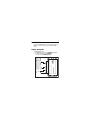
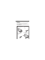
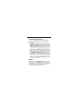
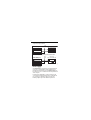
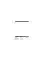
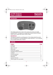
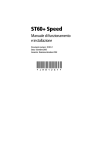
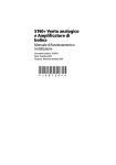
NMEA Multiplexer
Owner’s Handbook
Document Number: 81250-1
Date: February 2005
© Copyright Raymarine (UK) Ltd 2005
i
Preface
Congratulations on having bought a Raymarine NMEA
Multiplexer. This enables you to combine NMEA outputs from up
to four devices, to provide a combined output to four other
devices.
CAUTION: Electrical safety
Make sure you have switched off the power supply
before you start installing this product.
Important information
To the best of our knowledge, the information in this handbook was correct
when it went to press. However, Raymarine cannot accept liability for any
inaccuracies or omissions it may contain.
In addition, our policy of continuous product improvement may change
specifications without notice. Therefore, Raymarine cannot accept liability
for any differences between the product and this guide.
EMC Installation Guidelines
All Raymarine equipment and accessories are designed to the best industry
standards for use in the recreational marine environment.
Their design and manufacture conforms to the appropriate Electromagnetic
Compatibility (EMC) standards, but correct installation is required to ensure
that performance is not compromised. Although every effort has been taken
to ensure that they will perform under all conditions, it is important to
understand what factors could affect the operation of the product.
The guidelines given here describe the conditions for optimum EMC
performance, but it is recognized that it may not be possible to meet all of
these conditions in all situations. To ensure the best possible conditions for
EMC performance within the constraints imposed by any location, always
ensure the maximum separation possible between different items of
electrical equipment.
ii
For optimum EMC performance, it is recommended that wherever
possible:
• Raymarine equipment and cables connected to it are:
• At least 3 ft (1 m) from any equipment transmitting or cables carrying
radio signals e.g. VHF radios, cables and antennas. In the case of SSB
radios, the distance should be increased to 7 ft (2 m).
• More than 7 ft (2 m) from the path of a radar beam. A radar beam can
normally be assumed to spread 20 degrees above and below the
radiating element.
• The equipment is supplied from a separate battery from that used for
engine start. Voltage drops below 10 V in the power supply to our products, and starter motor transients, can cause the equipment to reset. This
will not damage the equipment, but may cause the loss of some information and may change the operating mode.
• Raymarine specified cables are used. Cutting and rejoining these cables
can compromise EMC performance and must be avoided unless doing so
is detailed in the installation manual.
• If a suppression ferrite is attached to a cable, this ferrite should not be
removed. If the ferrite needs to be removed during installation it must be
reassembled in the same position.
Suppression Ferrites
D3548-7
The following illustration shows typical cable suppression ferrites used with
Raymarine equipment. Always use the ferrites supplied by Raymarine.
Connections to Other Equipment
If your Raymarine equipment is to be connected to other equipment using a
cable not supplied by Raymarine, a suppression ferrite MUST always be
attached to the cable near the Raymarine unit.
iii
Contents
Preface ........................................................................................ i
CAUTION: Electrical safety ........................................ i
Important information ........................................................... i
EMC Installation Guidelines .................................................. i
Suppression Ferrites ........................................................ ii
Connections to Other Equipment .................................... ii
Introduction ............................................................................... 1
Inputs & outputs ........................................................................ 1
NMEA inputs ........................................................................ 2
Input priorities ................................................................. 2
NMEA outputs ...................................................................... 2
Installation ................................................................................ 3
Mounting ............................................................................. 3
Connections ......................................................................... 4
Real-time or buffered inputs ............................................ 4
NMEA in .......................................................................... 4
NMEA out ............................................................................. 5
Power supply ........................................................................ 6
CAUTION: Electrical Safety ....................................... 7
Securing cables ..................................................................... 7
Indicators ................................................................................... 7
Data indicator lit ................................................................... 7
Overflow indicator lit ............................................................ 7
Both indicators lit ................................................................. 8
Maintenance ............................................................................. 8
Disposal ..................................................................................... 8
Specifications ............................................................................ 9
iv
1
Introduction
The Raymarine NMEA Multiplexer combines data from up to four
NMEA-0183 devices to provide a single, multiplexed NMEA
output.
Inputs & outputs
The NMEA Multiplexer has:
• Four NMEA inputs (listener-ports), NMEA In 1, 2, 3 & 4.
• One NMEA output (talker-port), NMEA Out
• One common terminal NMEA Out Com.
D7684-1
PWR +12/24V
GND
Data
Not used
NMEA-0183 Multiplexer
NMEA Out a
NMEA Out b
NMEA Out Com
NMEA Out Shld
Overflow
NMEA In 1a
NMEA In 1b
NMEA In 2a
NMEA In 2b
NMEA In 3a
NMEA In 3b
NMEA In 4a
NMEA In 4b
NMEA In Shld
2
NMEA inputs
Each NMEA in (listener) port is a differential pair across
terminals a and b, and can receive NMEA data from one device.
The speed of each listener port is fixed at 4800 baud.
NMEA data on listener ports 1 and 2 is multiplexed in real time
(i.e. unbuffered).
NMEA data on listener ports NMEA In 3 and 4 is fed via a
discrete buffer for each port. Each buffer holds approximately
2 seconds of NMEA data.
Input priorities
Data at the listener ports is prioritized, so that each NMEA in
port is read twice as often as the next one. Thus for example, data
at input 1 is read in twice as often as data at input 2, four times as
often as input 3 and eight times more often than input 4.
NMEA outputs
The NMEA Out (talker) port is a differential pair across terminals
a and b, and feeds multiplexed NMEA data from all the NMEA
inputs, to up to four products.
3
Installation
Mounting
As the NMEA Multiplexer is not waterproof, it must be fitted in a
location where it will not come into contact with water.
Secure the NMEA Multiplexer to a suitable surface, as shown in
the following illustration.
1. Place the NMEA Multiplexer at
the intended location and mark
holes for fixing screws.
2. Drill two 1/8"(3.4 mm) pilot
holes for NMEA Multiplexer
screws.
Da
ta
Ov
erflo
w
EA
-01
83
Mu
ltip
lex
er
3. Countersink pilot holes to
prevent damage to the
mounting surface.
4. Secure the NMEA
Multiplexer with the
screws provided.
Da
ta
Ov
erflo
w
NM
EA
-01
83
Mu
ltip
lex
er
D7556-1
NM
4
Connections
Real-time or buffered inputs
Before connecting NMEA inputs to your NMEA Multiplexer,
consider whether they should be connected as real time or
buffered inputs:
• Data running at a fast rate and consisting of single sentences,
particularly time-critical data, should be connected to either
NMEA In 1 or NMEA In2, real time inputs. This includes
data from devices such as Fast Heading Sensors, and Fluxgate
Compasses. When data is processed in real time, some sentences may be lost, but the timing of the data is maintained
and there is no time delay. These inputs will store only one
NMEA sentence at a time, and thus prevent unwanted delays.
• Slower data that is input as a burst should be connected to
either NMEA In 3 or NMEA In 4, as buffered inputs. This
includes data such as GPS, route and depth information, for
which the timing is less critical. These inputs can store multiple
sentences (12 to 70, depending on length). This is necessary
for devices such as GPS, which can output 10 sentences at
once, every 1 or 2 seconds.
NMEA in
Connect an unused pair of NMEA In a and b terminals on the
NMEA Multiplexer to the NMEA output port of each device from
which you wish to receive NMEA data. The manner in which the
connections are made depends on whether the device has a
differential or single ended output, as follows:
5
Device with
differential NMEA output
& shield connection
Cable
shield
NMEA Multiplexer
NMEA out +
NMEA In a
NMEA out -
NMEA In b
Shield
Device with
differential NMEA output
but no shield connection
Cable
shield
NMEA Multiplexer
NMEA out +
NMEA In a
NMEA out -
NMEA In b
Shld
Note: NMEA outputs from Raymarine products are differential.
Device with
single-ended NMEA output
NMEA out +
Cable
shield
NMEA Multiplexer
NMEA In a
D7587-1
NMEA In b
Ground
NMEA out
Connect the a and b terminals of the NMEA Out connector to
the listening ports of up to four devices to which you wish to
transmit multiplexed data. The manner in which the connections
6
are made depends on whether the device has a differential or
single ended output, as follows:
NMEA Multiplexer
Cable
shield
Device with
differential NMEA input
NMEA Out a
NMEA in +
NMEA Out b
NMEA in -
Shld
Note: NMEA inputs on Raymarine products are differential.
NMEA Multiplexer
NMEA Out a
NMEA Out Com
Cable
shield
Device with
single-ended NMEA input
NMEA in +
Ground
D7586-1
Shld
Power supply
The NMEA Multiplexer operates from a dc supply voltage in the
range 8 V to 30 V and provides protection against reversed
polarity. It is recommended to connect the NMEA Multiplexer to
the same power source or circuit breaker as the ships instruments
and/or computer.
Protect the power supply with a 0.5 A fuse. The wires used to
connect the power supply must be less than 50 m in length and
have a total cross-sectional area of at least 0.2 mm2. The
following examples represent the minimum requirement:
7
• 24 AWG single-strand wire.
• 7/0.2 multi-strand wire, i.e. 7 strands, each of 0.2 mm diameter
CAUTION: Electrical Safety
Before connecting power to the NMEA Multiplexer,
turn off the power supply.
Connect either a 24 V or 12 V power supply, via a 0.5 A fuse, as
follows:
0V
NMEA Multiplexer
PWR +12/24V
GND
D7588-1
0.5 A fuse
+12 V or +24 V
Securing cables
When you have connected all cables, use appropriate cable ties
and/or clamps to make sure the cables are physically secure and
cannot be accidentally pulled from their connectors.
Indicators
Data indicator lit
A green Data LED blinks when valid NMEA data is received at the
listener ports, to indicate satisfactory connection and polarity of
the connected device. The Data LED will not blink if the input
polarity is reversed.
Overflow indicator lit
A red Overflow LED indicates a buffer overflow, i.e. that more
data is coming in than can be transmitted. When a buffer is full,
8
partially received sentences will be discarded, to ensure that the
NMEA Multiplexer only passes complete and valid sentences.
You may be able to resolve this overflow situation if you:
• Set up the devices on the listener ports to send less data or
data at greater intervals. If possible, disable non-relevant sentences.
• Swap the input devices to different listener ports.
Both indicators lit
Both LED s will blink once when power is applied to the NMEA
Multiplexer. If the red LED stays lit, this indicates that a hardware
error was found during self-test.
Maintenance
There are no user-serviceable parts inside the Raymarine NMEA
Multiplexer. However periodically check to ensure that the
connections to it are secure, and that the condition of the
connecting cables is satisfactory.
Disposal
When you want to dispose of this product, do so in accordance
with local regulations.
9
Specifications
Supply voltage:
8 V to 30 V dc, protected against reversed
polarity.
Supply protection:
0.5 A fuse
Supply connection:
Minimum requirement either:
24 AWG single-strand wire.
or
7/0.2 multi-strand wire.
Current consumption:
70 mA maximum, with fully loaded talker ports.
Inputs:
4 x NMEA-183, galvanically isolated.
Input resistance:
>800 Ohm.
Outputs:
1 x NMEA-183.
Buffers:
2 buffers of 1000 characters (NMEA In 3 and
NMEA In 4 only).
NMEA Out:
Combined data from NMEA inputs.
Speed NMEA in:
4800 baud.
Speed NMEA out:
4800 baud.
Indicators:
Overflow and Data LEDs.
Dimensions:
138 x 72 x 33 mm.
Housing:
Flame retardant ABS.
10
Raymarine UK Ltd,
Quay Point,
Northarbour Road
Portsmouth,
Hampshire PO6 3TD,
United Kingdom.
Tel: +44 (0) 23 9269 3611
Fax: +44 (0) 23 9269 4642
www.raymarine.com
Raymarine Inc,
22 Cotton Road,
Unit D, Nashua,
New Hampshire 03063-4219,
USA.
Tel: +1 603.881.5200
Fax: +1 603.864.4756
www.raymarine.com