1
Agilent Technologies 8510XF
Network Analyzer System
Service Quick
Reference Guide
Agilent Part Number: E7340-90013
Printed in USA
Print Date: May 2002
Supersedes: June 2001
Notice
Restricted Rights Legend
If software is for use in the performance of a U.S. Government prime
contract or subcontract, Software is delivered and licensed as "Commercial
computer sofware" as defined in DFAR 252.227-7014 (June 1995), or as a
"commercial item" as defined in FAR 2.101(a) or as "Restricted computer
software" as defined in FAR 52.227-19 (June 1987) or any equivalent agency
regulation or contract clause. Use, duplication or disclosure of Software is
subject Agilent Technologies’ standard commercial license terms, and nonDOD Departments and Agencies of the U.S. Government will receive no
greater than Restricted Rights as defined FAR 52.227-19(c)(1-2) (June
1987). U.S. Government users will receive no greater than Limited Rights as
defined in FAR 52.227-14 (June 1987) or DFAR 252.227-7015 (b)(2)
(November 1995), as applicable in any technical data.
Hewlett-Packard to Agilent Technologies Transition
This documentation supports a product that previously shipped
under the Hewlett-Packard company brand name. The brand
name has now been changed to Agilent Technologies. The two
products are functionally identical, only our name has changed.
The document still includes references to Hewlett-Packard
products, some of which have been transitioned to Agilent
Technologies.
Windows ® is a registered copyright of Microsoft corportation.
© Copyright 1998, 2001–2002
ii
Agilent Technologies, Inc
8510XF Service Quick Reference Guide
What You’ll Find in This Manual…
Chapter 1
Installation “Preflight” Checkout
Chapter 2
Upgrading a Source for 8510XF
Chapter 3
Making 8510XF Adjustments
•
•
•
•
Vertical Alignment Adjustment
Degaussing the Display
8360 Series Sources Full User CAL
Power Level Calibration
❍
Detector Gain Cal
❍
Conversion Loss Cal
Chapter 4
Performance Verification
Chapter 5
System Level Servicing and Troubleshooting
•
•
Theory of Operation
Troubleshooting Block Diagrams
8510XF Service Quick Reference Guide iii
Warranty
Certification
Agilent Technologies certifies that this product met its published
specifications at the time of shipment from the factory. Agilent Technologies
further certifies that its calibration measurements are traceable to the United
States National Institute of Standards and Technology (NIST, formerly
NBS), to the extent allowed by the Institute’s calibration facility, and to the
calibration facilities of other International Standards Organization members.
DOCUMENTATION
WARRANTY
THE MATERIAL CONTAINED IN THIS DOCUMENT IS
PROVIDED "AS IS," AND IS SUBJECT TO BEING CHANGED,
WITHOUT NOTICE, IN FUTURE EDITIONS. FURTHER, TO
THE MAXIMUM EXTENT PERMITTED BY APPLICABLE LAW,
AGILENT DISCLAIMS ALL WARRANTIES, EITHER EXPRESS
OR IMPLIED WITH REGARD TO THIS MANUAL AND ANY
INFORMATION CONTAINED HEREIN, INCLUDING BUT NOT
LIMITED TO THE IMPLIED WARRANTIES OF
MERCHANTABILITY AND FITNESS FOR A PARTICULAR
PURPOSE. AGILENT SHALL NOT BE LIABLE FOR ERRORS
OR FOR INCIDENTAL OR CONSEQUENTIAL DAMAGES IN
CONNECTION WITH THE FURNISHING, USE, OR
PERFORMANCE OF THIS DOCUMENT OR ANY
INFORMATION CONTAINED HEREIN. SHOULD AGILENT
AND THE USER HAVE A SEPARATE WRITTEN AGREEMENT
WITH WARRANTY TERMS COVERING THE MATERIAL IN
THIS DOCUMENT THAT CONFLICT WITH THESE TERMS,
THE WARRANTY TERMS IN THE SEPARATE AGREEMENT
WILL CONTROL.
Assistance
Product maintenance agreements and other customer assistance agreements
are available for Agilent Technologies products.
For assistance, call your local Agilent Technologies office (refer to
“Contacting Agilent” on page v).
iv
8510XF Service Quick Reference Guide
Contacting Agilent
Online assistance: www.agilent.com/find/assist
United States
(tel) 1 800 452 4844
Latin America
(tel) (305) 269 7500
(fax) (305) 269 7599
Canada
(tel) 1 877 894 4414
(fax) (905) 282-6495
Europe
(tel) (+31) 20 547 2323
(fax) (+31) 20 547 2390
New Zealand
(tel) 0 800 738 378
(fax) (+64) 4 495 8950
Japan
(tel) (+81) 426 56 7832
(fax) (+81) 426 56 7840
Australia
(tel) 1 800 629 485
(fax) (+61) 3 9210 5947
Singapore
(tel) 1 800 375 8100
(fax) (65) 836 0252
Malaysia
(tel) 1 800 828 848
(fax) 1 800 801 664
Philippines
(tel) (632) 8426802
(tel) (PLDT subscriber only):
1 800 16510170
(fax) (632) 8426809
(fax) (PLDT subscriber only):
1 800 16510288
Thailand
(tel) outside Bangkok:
(088) 226 008
(tel) within Bangkok:
(662) 661 3999
(fax) (66) 1 661 3714
Hong Kong
(tel) 800 930 871
(fax) (852) 2506 9233
Taiwan
(tel) 0800-047-866
(fax) (886) 2 25456723
People’s Republic of
China
(tel) (preferred):
800-810-0189
(tel) (alternate):
10800-650-0021
(fax) 10800-650-0121
India
(tel) 1-600-11-2929
(fax) 000-800-650-1101
8510XF Service Quick Reference Guide v
Safety and Regulatory Information
Review this product and related documentation to familiarize yourself with
safety markings and instructions before you operate the instrument. This
product has been designed and tested in accordance with international
standards.
WARNING
The WARNING notice denotes a hazard. It calls attention to a
procedure, practice, or the like, that, if not correctly performed
or adhered to, could result in personal injury. Do not proceed
beyond a WARNING notice until the indicated conditions are
fully understood and met.
CAUTION
The CAUTION notice denotes a hazard. It calls attention to an operating
procedure, practice, or the like, which, if not correctly performed or adhered
to, could result in damage to the product or loss of important data. Do not
proceed beyond a CAUTION notice until the indicated conditions are fully
understood and met.
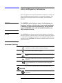
Instrument Markings
!
When you see this symbol on your instrument, you should refer to the
instrument’s instruction manual for important information.
This symbol indicates hazardous voltages.
The laser radiation symbol is marked on products that have a laser
output.
This symbol indicates that the instrument requires alternating current
(ac) input.
The CE mark is a registered trademark of the European Community.
If it is accompanied by a year, it indicates the year the design was
proven.
The C-Tick mark is a registered trademark of the Australian Spectrum Agency.
The CSA mark is a registered trademark of the Canadian Standards
Association.
vi
8510XF Service Quick Reference Guide
1SM1-A
This text indicates that the instrument is an Industrial Scientific and
Medical Group 1 Class A product (CISPER 11, Clause 4).
This ISM device complies with Canadian ICES-001.
Cet appareil ISM est conforme a la norme NMB du Canada.
This symbol indicates that the power line switch is ON.
This symbol indicates that the power line switch is OFF or in
STANDBY position.
Safety Earth
Ground
This is a Safety Class I product (provided with a protective earthing
terminal). An uninterruptible safety earth ground must be provided from the
main power source to the product input wiring terminals, power cord, or
supplied power cord set. Whenever it is likely that the protection has been
impaired, the product must be made inoperative and secured against any
unintended operation.
Before Applying Power
Verify that the product is configured to match the available main power
source as described in the input power configuration instructions in this
manual. If this product is to be powered by autotransformer, make sure the
common terminal is connected to the neutral (grounded) side of the ac power
supply.
8510XF Service Quick Reference Guide vii
Typeface Conventions
Typeface Conventions
•
Used to emphasize important information:
Use this software only with the xxxxxX system.
•
Used for the title of a publication:
Refer to the xxxxxX System-Level User’s Guide.
•
Used to indicate a variable:
Type LOAD BIN filename.
Instrument Display
•
Used to show on-screen prompts and messages that you will see on the
display of an instrument:
The xxxxxX will display the message CAL1 SAVED.
[Keycap]
•
Used for labeled keys on the front panel of an instrument or on a
computer keyboard:
Press [Return].
{Softkey}
•
Used for simulated keys that appear on an instrument display:
Press {Prior Menu}.
User Entry
•
Used to indicate text that you will enter using the computer keyboard;
text shown in this typeface must be typed exactly as printed:
Type LOAD PARMFILE
•
Used for examples of programming code:
Italics
#endif // ifndef NO_CLASS
Path Name
•
Used for a subdirectory name or file path:
Edit the file usr/local/bin/sample.txt
Computer Display
•
Used to show messages, prompts, and window labels that appear on a
computer monitor:
The Edit Parameters window will appear on the screen.
•
Used for menus, lists, dialog boxes, and button boxes on a computer
monitor from which you make selections using the mouse or keyboard:
Double-click EXIT to quit the program.
viii
8510XF Service Quick Reference Guide
Contents
Notice . . . . . . . . . . . . . . . . . . . . . . . . . . . . . . . . . . . . . . . . . . . . . . . . . . . . . ii
What You’ll Find in This Manual… . . . . . . . . . . . . . . . . . . . . . . . . . . . . . iii
Warranty . . . . . . . . . . . . . . . . . . . . . . . . . . . . . . . . . . . . . . . . . . . . . . . . . . . iv
Certification . . . . . . . . . . . . . . . . . . . . . . . . . . . . . . . . . . . . . . . . . . . . . iv
DOCUMENTATION WARRANTY . . . . . . . . . . . . . . . . . . . . . . . . . . iv
Assistance . . . . . . . . . . . . . . . . . . . . . . . . . . . . . . . . . . . . . . . . . . . . . . . iv
Contacting Agilent . . . . . . . . . . . . . . . . . . . . . . . . . . . . . . . . . . . . . . . . . . . v
Safety and Regulatory Information . . . . . . . . . . . . . . . . . . . . . . . . . . . . . . vi
Safety Earth Ground . . . . . . . . . . . . . . . . . . . . . . . . . . . . . . . . . . . . . . vii
Before Applying Power . . . . . . . . . . . . . . . . . . . . . . . . . . . . . . . . . . . vii
Typeface Conventions . . . . . . . . . . . . . . . . . . . . . . . . . . . . . . . . . . . . . . viii
1.
Installation “Preflight” Checkout
System Overview . . . . . . . . . . . . . . . . . . . . . . . . . . . . . . . . . . . . . . .
System Diagrams . . . . . . . . . . . . . . . . . . . . . . . . . . . . . . . . . . . . . . . . . .
Rack Diagram Configured for Coaxial Measurements . . . . . . . . . .
Rack Diagram Configured for Wafer-Probe Measurements . . . . . . .
Front View Cabling Diagram . . . . . . . . . . . . . . . . . . . . . . . . . . . . . .
Rear View Cabling (rack mounted source) . . . . . . . . . . . . . . . . . . . .
Rear View Cabling (table mounted source) . . . . . . . . . . . . . . . . . . .
8510XF Option 006 . . . . . . . . . . . . . . . . . . . . . . . . . . . . . . . . . . . . . . . .
2.
Upgrading a Source for 8510XF
3.
Making 8510XF Adjustments
Procedure 1. Vertical Alignment Adjustment . . . . . . . . . . . . . . . . . .
Procedure 2. DeGaussing (Demagnetizing) the Display . . . . . . . . .
Procedure 3. 8360 Series Sources Full User CAL . . . . . . . . . . . . . .
Procedure 3A. 8360 Series Sources Modulator Offset and Gain
Adjustment (8510XF RF source only) . . . . . . . . . . . . . . . . . . . .
Procedure 4. Power Level Calibration . . . . . . . . . . . . . . . . . . . . . . .
4.
1-1
1-2
1-2
1-3
1-4
1-5
1-6
1-7
3-3
3-4
3-5
3-5
3-6
Performance Verification
Verification Overview . . . . . . . . . . . . . . . . . . . . . . . . . . . . . . . . . . . . . .
When to Verify . . . . . . . . . . . . . . . . . . . . . . . . . . . . . . . . . . . . . . . . .
Materials Required . . . . . . . . . . . . . . . . . . . . . . . . . . . . . . . . . . . . .
Calibration and Frequency Ranges . . . . . . . . . . . . . . . . . . . . . . . . . .
Verification Setup . . . . . . . . . . . . . . . . . . . . . . . . . . . . . . . . . . . . . . . . .
General Preparation . . . . . . . . . . . . . . . . . . . . . . . . . . . . . . . . . . . . .
Software Installation . . . . . . . . . . . . . . . . . . . . . . . . . . . . . . . . . . . . .
Software Configuration . . . . . . . . . . . . . . . . . . . . . . . . . . . . . . . . . .
Verification Procedures . . . . . . . . . . . . . . . . . . . . . . . . . . . . . . . . . . . . .
Low Band Verification (< 50 GHz) . . . . . . . . . . . . . . . . . . . . . . . . .
4-1
4-1
4-2
4-2
4-4
4-4
4-4
4-5
4-8
4-8
8510XF Service Quick Reference Guide Contents ix
High Band Verification (> 50 GHz) . . . . . . . . . . . . . . . . . . . . . . . .
CW Frequency Accuracy Test . . . . . . . . . . . . . . . . . . . . . . . . . . . . . . .
Materials Required . . . . . . . . . . . . . . . . . . . . . . . . . . . . . . . . . . . . .
Procedure . . . . . . . . . . . . . . . . . . . . . . . . . . . . . . . . . . . . . . . . . . . . .
Performance Test Record . . . . . . . . . . . . . . . . . . . . . . . . . . . . . . . .
5.
4-10
4-12
4-12
4-12
4-14
System Level Servicing & Troubleshooting
Theory of Operation . . . . . . . . . . . . . . . . . . . . . . . . . . . . . . . . . . . . . . . . 5-2
Millimeter Wave Controller . . . . . . . . . . . . . . . . . . . . . . . . . . . . . . . 5-4
Frequency Bands . . . . . . . . . . . . . . . . . . . . . . . . . . . . . . . . . . . . . . . . 5-4
8510XF Firmware Specifications . . . . . . . . . . . . . . . . . . . . . . . . . . . . . . 5-6
Hardware States . . . . . . . . . . . . . . . . . . . . . . . . . . . . . . . . . . . . . . . . 5-7
Instrument States . . . . . . . . . . . . . . . . . . . . . . . . . . . . . . . . . . . . . . . . 5-7
Power Level Check . . . . . . . . . . . . . . . . . . . . . . . . . . . . . . . . . . . . . . . . . 5-8
Test Plots . . . . . . . . . . . . . . . . . . . . . . . . . . . . . . . . . . . . . . . . . . . . . 5-10
x 8510XF Service Quick Reference Guide
1
Installation “Preflight” Checkout
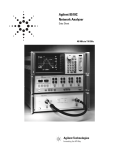
System Overview
The 8510XF network analyzer system has been designed to measure
broadband devices to 110 GHz, on-wafer or coax, fully calibrated, in a
single frequency sweep.
Single RF connection to 110 GHz
The 8510XF system provides frequency coverage from 45 MHz to 110 GHz
in a single sweep with a single connection.
Millimeter-wave measurements in 1.0 mm coax
With a single connection, fully error-corrected measurements to 110 GHz
are made in 1.0 mm coax. Making millimeter-wave measurements in
1.0 mm coax delivers uncompromised performance and improved
productivity compared to waveguide.
Convenient millimeter-wave on-wafer measurements
The 8510XF system is designed for convenient on-wafer measurements
using the 1.0 mm coax connector to interface with the 1.0 mm wafer probe.
Broadband calibration with built-in firmware
The built-in firmware of the 8510XF system enables you to perform a single
calibration from 45 MHz to 110 GHz, either in coax or on-wafer.
8510XF Service Quick Reference Guide 1-1
Installation “Preflight” Checkout
System Diagrams
System Diagrams
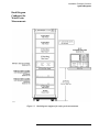
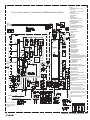
Rack Diagram
Configured for
Coaxial Measurements
Figure 1-1
Rack diagram configured for coaxial measurements
1-2 8510XF Service Quick Reference Guide
Installation “Preflight” Checkout
System Diagrams
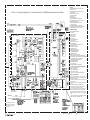
Rack Diagram
Configured for
Wafer-Probe
Measurements
Figure 1-2
Rack diagram configured for wafer-probe measurements
8510XF Service Quick Reference Guide 1-3
Installation “Preflight” Checkout
System Diagrams
Front View
Cabling Diagram
Figure 1-3
Front view wiring diagram
2.4 mm
3.5 mm
SMA
testhead.cdr
Figure 1-4
Test head connectors
1-4 8510XF Service Quick Reference Guide
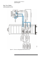
Rear View Cabling
(rack mounted source)
Figure 1-5
Installation “Preflight” Checkout
System Diagrams
Rear view wiring diagram (rack mounted source)
8510XF Service Quick Reference Guide 1-5
Installation “Preflight” Checkout
System Diagrams
Rear View Cabling
(table mounted source)
Figure 1-6
Rear view wiring diagram (table mounted source)
1-6 8510XF Service Quick Reference Guide
Installation “Preflight” Checkout
8510XF Option 006
8510XF Option 006
8510XF Option 006 provides the capability to add an additional 8510 series
test set provided Option 001 is installed in the test set. Option 006 includes:
•
•
Figure 1-7
Coupler and amplifier added to millimeter-wave controller
2.4 mm termination added to rear panel
8510XF Option 006
The configuration for the 8510XF Option 006 is as shown in Figure 1-8.
Figure 1-8
Multiple test set example application
8510XF Service Quick Reference Guide 1-7
Installation “Preflight” Checkout
8510XF Option 006
1-8 8510XF Service Quick Reference Guide
2
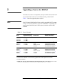
Upgrading a Source for 8510XF
All 8360 series sources are compatible, but only the 83621A/B or 83651A/B
are recommended in order to insure full functionality of the 8510XF.
Table 2-1 shows the upgrade options required.
NOTE
83651/21A and 83650/20A/B will also work for upgraded 8510XF systems
as long as it has test port flatness correction modification or capability, rear
panel output (Option 004), and 1 Hz frequency resolution (Option 008)
installed.
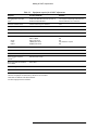
Table 2-1
Source Upgrades
Model
Maximum Power at
Highest Frequency
83620B/21B
83650A/B
83651A/B
+ 13 dBm
+ 2.5 dBm
+ 2.5 dBm
2
83621A
83631A 2
+13 dBm
+ 10 dBm
83620A 2
83623A 2 4
83624A 2
83630A 2
83640A 2
+ 13 dBm
+ 17 dBm
+ 20 dBm
+ 10 dBm
+ 26 dBm
Serial Prefix
Required for Test Port
Flatness Correction
All
No modification required. 1
< 3103A
3103A
3104A to 3111A
≥ 3112A
83601A upgrade kit.3
08360-60167 firmware kit
08360-60201 firmware kit
No modification required. 1
≤ 3103A
3104A to 3111A
≥ 3112A
≥ 3145A
08360-60167 firmware kit
08360-60201 firmware kit
No modification required. 1
No modification required. 1
1. Fully compatible at time of shipment.
2. Can be used for 8510XF LO source when upgraded and includes Options 004 and 008.
3. Includes installation.
4. 83623L, 30L, 40L and 50L, with Option 004 and 008, will also work as LO source, but do not have
modulation capability (83623L maximum power at highest frequency is + 15 dBm).
8510XF Service Quick Reference Guide 2-1
Upgrading a Source for 8510XF
2-2 8510XF Service Quick Reference Guide
3
Making 8510XF Adjustments
NOTE
This chapter covers both the CRT and LCD displays. Some display-related
adjustments apply only to instruments with CRT display.
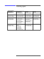
The following table provides adjustments most frequently needed for
8510XF system service. Most of the 8510XF is self-adjusting except for the
following:
Table 3-1
Frequently used 8510XF adjustments
Procedure1
Title
Adjustment Function
Assembly Adjusted
1
Vertical Alignment Adjustment2
Aligns softkey labels and mechanical
softkey buttons.
A11
2
Degausing (Demagnetizing) the 85101
display2
Demagnetize the display.
3
8360 Series Sources Full User CAL
4
Power Level Calibration
Insures level power at the test ports
Leveling DAC/ EEPROM, A16,
and Leveling Compensation
Board, A7
1. Reference subsequent sections in this document.
2. These adjustments apply to a CRT-based display only.
8510XF Service Quick Reference Guide 3-1
Making 8510XF Adjustments
Table 3-2
Equipment required for 8510XF adjustments
Equipment
Recommended Model
Substitute
CRT demagnetizer or bulk tape
eraser1
Radio Shack Model 44-233 Techno Tool (USA) or
Nietronix (Europe) 692PR022
1 to 2 amp pencil sharpening motor (base held
near CRT with motor on), or electric drill
Flat-head screwdriver (small)
At least 2 inches long, non-conductive
none
10 dB pad
8493C
8360 series source with built-in attenuator
85102A/B and test set adjust software
Part Number 08510-10024
Rev. A.01.10
Power Meter
437B power meter
438A or EPM-441A power meter
8481A or 8482A
8487A power sensor
V8486A power sensor
W8486A power sensor
N/A
N/A
Only available as a special
N/A
Power Sensors:
50 GHz
V band
W band
Adapter, 2.4 to 1.0 mm (f-f)
85059A K01
Adapter, V-band to 1.0 mm (f-f)
V281C
Adapter, W-band to 1.0 mm (f-f)
W281C
Laptop, personal computer or
controller 2, 3
9000 series 200 or larger
8510XF port power level calibration
check software
08510-100xx
BASIC 6.3 or higher 4
E2060B
Agilent VEE 4.0 Installation
E2120-13605
1. These adjustments apply to a CRT based display only.
2. Minimum 4 megabytes of available memory after BASIC has been loaded.
3. With BASIC for Windows and PCMCIA-GPIB card.
4. Includes language extensions and drivers.
3-2 8510XF Service Quick Reference Guide
Making 8510XF Adjustments
Procedure 1.
Vertical Alignment
Adjustment
NOTE
This procedure applies to a CRT based display only.
NOTE
The vertical alignment can be affected by magnetic interference. Before
adjusting the vertical position, be sure the analyzer is in a non-magnetic
environment and the CRT is degaussed.
Perform the following steps to adjust the vertical alignment.
1. Switch on the system and allow it to warm up for 60 minutes.
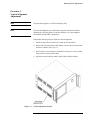
2. Remove the side panel nearest the display to access the vertical position
and focus controls. See Figure 3-1.
3. Insert a narrow, non-conductive, flathead screwdriver (2 or more inches
long) into the vertical position hole.
4. Adjust the control until the softkey labels align with the softkeys.
Figure 3-1
Vertical adjustment location
8510XF Service Quick Reference Guide 3-3
Making 8510XF Adjustments
Procedure 2.
DeGaussing
(Demagnetizing) the
Display
NOTE
This procedure applies to a CRT based display only.
Use any CRT demagnetizer or bulk tape eraser for this procedure. The color
monitor display is very susceptible to external magnetic fields, such as metal
frame tables, welded cabinets, the earth, unshielded motors, and other
sources. The usual symptom is discoloration or slight dimming of the
display (usually near a top corner of the CRT). In extreme cases, a total color
shift may be observed. For example, a trace that was red may shift to green.
This shift does not suggest a problem with the display. It is characteristic of
color displays needing demagnetizing. In countries using 50 Hz, some 10 Hz
jitter may be observed. If this problem is observed, remove the device
causing the magnetic field.
If the display becomes magnetized or if color purity is a problem, cycle the
power several times. Leave the instrument off for at least 15 seconds before
switching power on. This will trigger the automatic degaussing circuit in the
display. If this is insufficient to restore color purity, use a commercially
available demagnetizer (either a CRT demagnetizer or a bulk tape eraser). In
an emergency, you can use a running electric drill or a pencil sharpener that
draws 1/2 to 2 amps through its AC motor winding. Follow the
manufacturer’s instructions keeping in mind that it is imperative when
demagnetizing a display that the degausser is kept farther than 4 inches
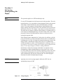
(10 cm) from the face of the CRT. Generally, degaussing is done with a slow
rotary motion of the degausser, moving it in a circle of increasing radius
while simultaneously moving away from the CRT. The following figure
illustrates the motion for degaussing the display.
CAUTION
Applying an excessively strong magnetic field to the CRT face can
permanently destroy the CRT.
Figure 3-2
Using a Degausser on the display
3-4 8510XF Service Quick Reference Guide
Making 8510XF Adjustments
Procedure 3.
8360 Series Sources
Full User CAL
Full User CAL initiates a full synthesizer calibration. The calibration
performed is instrument state dependent. For example, if the synthesizer is
in ramp sweep mode, a sweep span and an auto track calibration are
performed. If the synthesizer has amplitude modulation active on an SW
signal, then RF peaking and AM bandwidth calibrations are performed. For
8510XF purposes, only ramp-sweep mode is needed.
Perform the following calibration procedure:
1. On the 8360, press [PRESET] [USER CAL].
2. Select {Full User CAL}. Wait for the calibration to complete (usually less
than a minute).
Attenuation needed
If the 8360 series source does not have a built-in attenuator, you will be
prompted to connect a 10 dB attenuator to the 8360 series RF output port.
Auto track is done as part of Full User CAL.
NOTE
If the 8360 series source does not have a front panel, use the 8360 source
front panel emulator in the 8510C network analyzer (refer to the “Service
Program” section in the 8510C On-Site Service Manual). For the RF source
calibration, the front-panel emulator will default to GPIB address 19. For the
LO source calibration, change the GPIB address in the front panel emulator
to 18.
Procedure 3A.
8360 Series Sources
Modulator Offset and
Gain Adjustment
(8510XF
RF source only)
Modulator offset and gain adjustment optimizes the modulator in the 8360
series source for maximum performance. This is necessary since the RF
source is part of the 8510XF level control (refer to Figure 3-3 on page 3-6).
This should be done before the conversion loss calibration is performed on
systems with older sources or sources which may be out of calibration.
Adjust the RF source using the procedure “Modulator Offset and Gain
Adjustment” in the 8360 Series Synthesized Sweeper Service Guide’s
“Adjustments” chapter.
8510XF Service Quick Reference Guide 3-5
Making 8510XF Adjustments
Procedure 4.
Power Level
Calibration
Power level calibration insures leveled power at ports 1 and 2. To level the
power, we sense the IF signal which correlates to RF level. Since the
translation function is frequency dependent, we need to measure the
translation function using the conversion loss calibration procedure. The
power level calibration is accomplished using IF leveling as shown in the
following circuit.
Figure 3-3
8510XF level control
3-6 8510XF Service Quick Reference Guide
Making 8510XF Adjustments
Detector Gain Cal
Before we begin the conversion loss calibration, we must perform a detector
gain calibration to compensate for the imprecision of the detector board
(E7340-60015 A7). Perform the following procedure for the detector gain
calibration:
1. Under the Auxiliary Menus, press [System] hard key.
2. Press {More} softkey.
3. Press {RF Power Config} softkey.
4. Press {More} softkey.
5. Press {Reset Det Gain Cal} softkey.
6. Follow the on-screen instructions until cal is completed.
CAUTION
If the operating system is reloaded, it is necessary to perform the detector
gain calibration.
NOTE
It is recommended that this 5-minute calibration be performed once a month.
Additionally, a CW frequency accuracy test should be performed prior to
doing the conversion loss and power level flatness calibrations. Refer to
“CW Frequency Accuracy Test” on page 12.
Conversion Loss
Calibration
After performing a detector gain cal, you will be ready to perform the RF to
IF conversion loss calibration. This calibration provides the absolute power
level information at 25/50 MHz intervals over the entire frequency range of
the E7340/50A to compensate for conversion losses in the E7340/50A so
that ports 1 and 2 will be power leveled.
a. The external controller with its software changes the 8510XF CW
frequency and reads the power meter.
b. The entire frequency range is stepped in 25/50 MHz increments at
approximately 2200 points per port (25 MHz steps from 45 MHz to
18 GHz, and 50 MHz steps from 18 GHz to 110 GHz).
c. The result is stored in the millimeter controller EEPROM memory
board (A16) after all bands and heads are measured and should be
valid for one year or until a test head is repaired or replaced.
8510XF Service Quick Reference Guide 3-7
Making 8510XF Adjustments
To perform the conversion loss calibration:
Use the following procedure to perform the conversion loss calibration.
1. Load the BASIC, version 6.3 or greater.
2. Calibrate and zero the power sensor, and enter all cal factors versus
frequency of the 3 or 4 sensors into the text file of the conversion loss
calibration program.
3. Connect the power sensor to the left or right test head and press [ENTER].
4. Create a power sensor cal factor test file. Using MS Windows Notepad,
enter the following values in the respective columns:
Column
Entry
First
Frequency (GHz)
Second
Cal Factor
Third
Sensor #3
Save this file as XFPWRCAL.PMC, and in the same directory as your
conversion loss cal program.
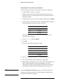
5. Load xfpwcal.bas, and press [ENTER].
6. Press {Run}.
7. Select one of the following frequency ranges:
Selection
Frequency Range
1
0.045 to 110 GHz
2
2 to 110 GHz
3
0.045 to 85 GHz
4
2 to 85 GHz
8. Select (1) for the left test-head, or (2) for the right test-head.
9. Enter the serial number of the test head up to eight digits.
10. Approximately 20 frequencies will be used to check the 8510XF power
control. These frequencies and the corresponding levels will be
displayed if all is okay. If not, the display will have an error message
which indicates that the 8510XF leveling loop must be corrected.
NOTE
Refer to Performance Verification, page 4-1, for details on the types of
computers and software needed to run the Performance Verification and
conversion loss calibration programs.
3-8 8510XF Service Quick Reference Guide
4
Performance Verification
Verification Overview
NOTE
The verification procedures in this chapter work for all 8510 and 8510XF
hardware configurations by substituting the proper 8510 source, test set,
accessories, and millimeter wave controller.
Performance verification software Rev. A.05.00 or greater will be available
only in DOS format, and will work with laptops or PCs that have the
required accessories installed. Refer to “Materials Required” on page 4-2.
When to Verify
After installation of the system is complete, a performance verification is
necessary to assure proper system operation. This initial verification is
included with the installation.
After the initial verification, the verification should be repeated once a year.
This recommended interval assumes that Agilent cables are used with the
system.
If non-Agilent cables, adaptors, or other fixtures are used, the verification
schedule must be determined by the user, as the characteristics of these
devices are unknown. In establishing a verification schedule, the following
factors should be considered:
•
•
•
NOTE
Frequency of use
Amount of cable movement
Amount of drift occurring between prior verifications
Performance verification of a system performed at long intervals is not to be
confused with measurement calibration. Measurement calibration typically
is performed on a daily basis, or when measurement setup or conditions have
changed.
8510XF Service Quick Reference Guide 4-1
Performance Verification
Materials Required
Calibration and
Frequency Ranges
The following materials are required to run the tests:
•
•
•
8510XF system with accessories
•
Laptop or PC running BASIC for Windows (3.1/95/NT)
(Rev. 6.3 or greater)
•
•
•
GPIB Card for PCs (National Instruments or HP)
85059A 1.0 mm Precision Calibration and Verification Kit
PC-based, 8510 Specification and Performance Verification Software
(Rev. A.05.00 or greater; p/n 08510-10033)
PCMCIA Card for Omnibook or laptop
GPIB cable from PC to 8510XF
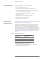
The 8510XF requires separate verifications for frequencies below and above
50 GHz (see on “Frequency ranges” on page 4-3).
A special two-band calibration procedure is required for the performance
verification of the 8510XF system (a measurement calibration is not
sufficient). There are up to three different calibrations and corresponding
frequency ranges required, which are stored in suggested locations in the
8510 analyzer (Refer to Table 4-1). For more information refer to the section
on “Frequency ranges” on page 4-3. The parameters for these calibrations
are set up automatically on the analyzer by the performance verification
software.
Table 4-1
Calibration storage locations
File Location Name:
Frequency Range of Data
Stored:
Cal Set 1
1-50 GHz1 (2-50 GHz)2
Cal Set 2
45 MHz1
Cal Set 3
50-110 GHz3
1. This calibration is for Option 005 systems only.
2. The frequency for standard systems is 2-50 GHz.
3. The frequency range shown is for the E7352A system only. The E7342A
system’s frequency range will be: 50-85 GHz.
4-2 8510XF Service Quick Reference Guide
Performance Verification
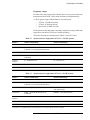
Frequency ranges
For most of the menu items in the software, there are two or more selections
that pertain to the 8510XF. These menu selections are differentiated by:
A. The frequency range of the millimeter wave subsystem
❍
❍
❍
E7352A: 110 GHz subsystem
E7342A: 85 GHz subsystem
Option 005: 45 MHz to 2 GHz
B. The portion of the subsystem’s frequency range that is being verified (the
ranges above and below 50 GHz are verified separately).
The menu selections are broken down in Tables 4-2 and 4-3, below.
Table 4-2
System hardware configuration (E7352A -- 110 GHz System)
Hardware
Selection (<50 GHz Range)
Selection (>50 GHz Range)
Network Analyzer
8510C -- Vector Network Analyzer
8510C -- Vector Network Analyzer
Test Set
E7352A -- 1.0 mm Subsystem (2-50 GHz)
E7352A005 -- 1.0 mm Subsystem (45MHz-50GHz)
E7352A110 -- 1.0 mm (50 GHz-110 GHz)
Source
8365xXF -- Synthesizer (45 MHz-50 GHz)
836xxXF -- Multiplied Synth. (above 50 GHz)
Calibration Kit1
85059A -- 1.0 mm (45 MHz-50 GHz) [Use w/
E7342A/52A]
85059A110 -- 1.0 mm (50 GHz-110 GHz)
Calibration
Technique
BL -- Broadband Load Cal
OS -- Offset Short Cal
Test Port Cables
DIRECTXF -- for 8510XF verification (1.0 mm-1.0 mm)
DIRECTXF -- for 8510XF verification (1.0 mm-1.0 mm)
Verification Kit
85059AOV -- 1.0 mm (45 MHz-50 GHz)
85059AOV110 -- 1.0 mm (above 50 GHz)
1. The 85059A --1.0 mm (45MHz-50GHz) [Use w/ 8517A/B] selection is not used for the 8510XF Performance Verification.
Table 4-3
System hardware configuration (E7342A -- 85 GHz System)
Hardware
Selection (<50 GHz Range)
Selection (>50 GHz Range)
Network Analyzer
8510C -- Vector Network Analyzer
8510C -- Vector Network Analyzer
Test Set
E7342A -- 1.0 mm Subsystem (2-50 GHz)
E7342A005 -- 1.0 mm Subsystem (45 MHz-50GHz)
E7342A85 -- 1.0 mm (50 GHz-85 GHz)
Source
8365xXF -- Synthesizer (45 MHz-50 GHz)
836xxXF -Synth. (above 50 GHz)
Calibration Kit1
85059A -- 1.0 mm (45 MHz-50 GHz) [Use w/
E7342A/52A]
85059A85 -- 1.0 mm (50 GHz-85 GHz)
Calibration
Technique
BL -- Broadband Load Cal
OS -- Offset Short Cal
Test Port Cables
DIRECTXF -- for 8510XF verification (1.0 mm-1.0 mm)
DIRECTXF -- for 8510XF verification (1.0 mm-1.0 mm)
Verification Kit
85059AOV -- 1.0 mm (45 MHz-50 GHz)
85059AOV110 -- 1.0 mm (above 50 GHz)
1. The 85059A --1.0 mm (45MHz-50GHz) [Use w/ 8517A/B] selection is not used for the 8510XF Performance Verification.
8510XF Service Quick Reference Guide 4-3
Performance Verification
Verification Setup
Verification Setup
General Preparation
Prepare for performance verification by completing the following steps:
1. Measure the environment temperature and humidity. The temperature
must be between +20 °C and +26 °C. Additionally, the temperature
cannot vary by more than 1°C after calibration.
2. Perform a good installation “preflight” checkout on the 8510XF system.
3. Power on the system components in the following order:
a. Sources
b. Millimeter wave controller
c. 8510XF
d. Controller (PC or laptop)
4. Remember to allow at least one hour for warm up of the components.
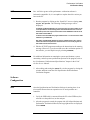
Software Installation
In order to verify performance, you must first install BASIC for Windows
and the 8510C Specification and Performance Verification software on a PC
(or controller).
NOTE
This manual documents the use of the verification software on a PC. Use of
the software on a controller is not documented.
The PC must have an INTEL 486 processor or higher, and must have at least
eight megabytes of memory available. The PC must also have an GPIB card
in order to communicate with the 8510XF.
1. Install BASIC for Windows (Revision 6.3 or later) on the PC following
the instructions on the first BASIC disk. The program will guide you
through the installation process. (For more detailed information, refer to
BASIC for Windows, Installing and Using Guide.) If you are installing
Revision 7.1 or later, install the Legacy Version.
2. Install the specification and performance verification software by
following the instructions on the disk label. The installation program
will lead you through the installation. In the process, a new program
group will be created, which includes the “Spec8510” icon.
4-4 8510XF Service Quick Reference Guide
Performance Verification
Verification Setup
NOTE
Rev. A.05.00 or greater of the performance verification software is
backwards compatible. So, it is acceptable to replace the older version you
have on the PC.
3. Run the program by clicking on the “Spec8510” icon or selecting: Start,
Programs, 8510, Spec8510. The following warning messages will be
displayed:
A valid Basic for Windows GPIB driver for your board (if any) has not been loaded. You can
run the Specifications and Uncertainty portions of the 8510 software but can not run the
Verification portion as this requires communication. Press CONTINUE to load and run the
8510 software without GPIB or:
To load the correct driver EDIT this program and Remove the “!” from in front of the LOAD
statement for your GPIB board.
After editing, type RE-STORE “AUTOST” to store the modified program. Then, close this
window and re-select the Specifications and Verification icon to re-run the program. The
8510 software should now load and run.
4. Edit the AUTOST program according to the instructions in the warning
message. (However, if you do not want to run the verification portion of
the software, you can skip this step by selecting CONTINUE.)
NOTE
For additional information on running the system specifications, system
uncertainty, and edit system specifications portions of the program, refer to
the “Performance Verification and Specifications” chapter in the 8510C
On-Site Service Manual.
5. After editing and storing the AUTOST file, exit the program by closing the
window and then restart the 8510 Specification and Performance
Verification Program.
Software
Configuration
NOTE
Once the Specifications and Verification Software is running, there is no
functional difference between operation on a PC and operation on a
controller.
1. Verify the GPIB cable is connected from the PC to the GPIB bus (also
referred to as the public bus) on the analyzer.
2. After the program is started, the program title (8510 Specifications and
Performance Verification Software) and copyright notices are displayed.
Select RESUME.
8510XF Service Quick Reference Guide 4-5
Performance Verification
Verification Setup
3. A screen prompt will give you the opportunity to set the date and time.
Press the [Y] key on the PC to skip this step, or press [N] to set the date
and time.
4. The program loads the System Configuration file, and displays the
System Hardware Configuration Menu. Use this menu to specify the
equipment you are using, and the frequency range you are verifying
(refer to “Frequency ranges” on page 4-3).
To set up for the first performance verification, select the proper
hardware setup for Low Band Verification (< 50 GHz) using Table 4-2
on page 4-3 for the E7352A 110 GHz system, or Table 4-3 on page 4-3
for the E7342A 85 GHz system.
a. Select NEXT or PREVIOUS to step through the list of selections for each
menu item.
b. Use the up and down arrow keys on the PC to advance from one
menu item to another.
c. Select DONE when you have made a selection for each menu item.
5. The main menu is displayed (see Table 4-4).
Table 4-4
Main menu
Softkey
Description
System Config
System Hardware and Software Configuration Menu
System Specs
System Spec Table Menu
System Uncert
System Uncertainty & Dynamic Accuracy Plot/Table Menu
Edit Specs
Edit the System Specifications
Verify System
System Performance Verification Menu
Quit Progam
Quit this Program
4-6 8510XF Service Quick Reference Guide
Performance Verification
Verification Setup
Printer selection
1. From the Main Menu (choosing printer options):
a. Select System config.
b. Select Software Config.
c. Select Printer Connected to:
2. Select printer output choice (refer to Table 4-5)
Table 4-5
Printer table of selections
Printer Connected To:
GPIB
WIN Printer1
LPT1
LPT2
File2
1. Windows default printer
2. Under Printer Redirection (File): Verify directory path exists
before entering name of path
3. Select Done and Previous Menu to return to Main Menu.
8510XF Service Quick Reference Guide 4-7
Performance Verification
Verification Procedures
Verification Procedures
Low Band Verification
(< 50 GHz)
The following steps assume the hardware configuration has been previously
setup for Low Band Verification (< 50 GHz) in step 4 on page 4-6 under
Software Configuration.
1. From the Main Menu select Verify System to go to the System Performance
Verification Menu.
2. Select Serial Numbers to enter serial numbers of system and components.
3. Select System Cal and follow the program prompts to calibrate the system
for frequencies <50 GHz. See Table 4-1 on page 4-2 for the calibrations
required and suggested calibration storage locations (also refer to the
“Two-Band Calibration Procedure for 8510XF Performance
Verification” art foldout at the end of this chapter).
a. Install the 1.0 mm female to female cable (8.8 cm, part number
11500-60001) onto the right test head (port 2) prior to calibration.
This cable is part of the 85059A 1.0 mm Precision Calibration and
Verification Kit and is considered to be a test port cable.
b. A full two-port calibration is required. A table of calibration
standards required for each frequency range can be found in the
85059A 1.0 mm precision calibration and verification kit manual, or
on the art foldout at the end of this chapter.
CAUTION
Do not remove this test port cable once the Calibration/Verification process
has begun. If the test port cable becomes loose or is removed during the
calibration/verification process, the calibration is invalid.
CAUTION
Do not pull on the connectors on the ends of the test port cable—this will
damage the cable. Avoid damaging the cable once it is connected to port 2
by carefully making the thru connection between the two test heads. This is
best done by placing the two test heads on a smooth surface and gently
sliding the right test head (port 2) towards the left test head (port 1).
4-8 8510XF Service Quick Reference Guide
Performance Verification
Verification Procedures
c. To make the thru connection, gently slide the right test (port 2)
towards the left test head (port 1) a little bit at a time, while turning
the threaded ring on the left head test port connector by hand onto
the cable attached to the right test head. Do not use the threaded ring
on the test port connector to pull the cable into the connector. Repeat
this process until the cable is firmly seated into port 1, then make the
threaded ring barely finger tight. Finally use the torque wrench on
the port 1 threaded ring and a backup wrench on the cable to tighten
the connection.
4. Select Select Standard to go to the Standard Selection Menu.
5. To verify the system, use the Verification Standards provided with the
85059A 1.0 mm Precision Calibration and Verification Kit (refer to
Table 4-6). Using the menu select the verification standard and enter the
standard’s serial number. The verification standards may be measured in
any order.
Table 4-6
NOTE
Verification standards from 1.0 mm calibration and verification kit
Type of Standard
Part Number
Mismatched Thru Adapter
85059-60016
Match Thru Adapter
85059-60017
It is recommended to connect the Verification Standards to the cable on
port 2 prior to attempting to connect to port 1. Then follow the
recommended procedure for making a thru connection outlined under step 3
above to avoid damaging the cable.
6. Use defaults for Cal Set for Broadband Measurement: 1 and Cal Set for 45 MHz
Measurement (If Required): 2 in the Standard Menu.
7. If your system has Option 005, verify that Cal Set for 45 MHz Measurement (If
Required) is set to Yes. Otherwise, set to No.
8. Select Done and follow the program prompts.
9. Select Measure Data to measure the verification standards. Follow the
program prompts.
10. When verification has been completed view the data, then print or save
(if required). If needed the verification standard can be remeasured by
selecting Repeat Measure.
8510XF Service Quick Reference Guide 4-9
Performance Verification
Verification Procedures
11. Select Select Standard to return to the Standard Selection Menu. Repeat
steps 5 through 10 above for the other verification standard (refer to
Table 4-6 on page 4-9).
12. Select Prior Menu until the Main Menu appears.
High Band Verification
(> 50 GHz)
NOTE
Before verification of the high band frequencies it is necessary to:
1) select new hardware for the system, and
2) perform a calibration (for the frequency band > 50 GHz).
1. From the Main Menu select System Config then Hardware Config.
2. Select the proper hardware setup for High Band Verification (> 50 GHz)
using Table 4-2 on page 4-3 for the E7352A 110 GHz System or
Table 4-3 on page 4-3 for the E7342A 85 GHz System.
3. Select Done and Prior Menu to return to Main Menu.
4. Select Verify System to go to the System Performance Verification Menu.
5. Select System Cal and follow the program prompts to calibrate the system
for frequencies >50 GHz. See Table 4-1 on page 4-2 for the calibrations
required and suggested calibration storage locations (refer to step 3 on
page 4-8).
6. Select Select Standard to go to the Standard Selection Menu.
7. To verify the system use the Verification Standards provided with the
85059A 1.0 mm Precision Calibration and Verification Kit (refer to
Table 4-6 on page 4-9). Using the menu select the verification standard
and enter the standard’s serial number. The verification standards may
be measured in any order.
NOTE
It is recommended to connect the Verification Standards to the cable on
port 2 prior to attempting to connect to port 1. Then follow the
recommended procedure for making a thru connection outlined under step 3
on page 4-8 to avoid damaging the cable.
8. Change default for Cal Set for Broadband Measurement from 1 to 3.
NOTE
It is suggested that the High Band Calibration be stored in Cal Set 3 (Refer
to Table 4-1 on page 4-2).
4-10 8510XF Service Quick Reference Guide
Performance Verification
Verification Procedures
9. Verify Cal Set for 45 MHz Measurement (If Required) is set to No.
10. Select Done and follow the program prompts.
11. Select Measure Data to measure the verification standards. Follow the
program prompts.
12. When verification has been completed view the data, then print or save
(if required). If needed the verification standard can be remeasured by
selecting: Repeat Measure.
13. Select Select Standard to return to the Standard Selection Menu. Repeat
steps 7 through 12 above for the other verification standard (refer to
Table 4-6 on page 4-9).
14. Select Prior Menu until the Main Menu appears.
15. Select Quit Program to exit the program, then close the program window to
finish.
8510XF Service Quick Reference Guide 4-11
Performance Verification
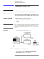
CW Frequency Accuracy Test
CW Frequency Accuracy Test
NOTE
The CW frequency accuracy test should be performed prior to doing the
conversion loss calibration adjustment or detector gain calibration.
Source frequency accuracy is tested across the entire sweep range for 8360
sources. The CW frequency accuracy is measured with a frequency counter.
Materials Required
The following materials are required to run the tests:
•
•
5343 Option 001, 10 MHz to 26.5 GHz frequency counter
10 dB pad
NOTE
If the source and test set operate below 500 MHz, connect the test set output
to the 10 Hz to 500 MHz BNC connector on the frequency counter. The
input switch on the frequency counter must also be in the 10 Hz to 500 MHz
position.
Procedure
1. Connect the equipment as shown in Figure 4-1.
Figure 4-1
CW frequency accuracy equipment setup
2. To preset the instruments, press INSTRUMENT STATE [RECALL] {MORE}
{FACTORY PRESET}. Disregard any error messages.
4-12 8510XF Service Quick Reference Guide
Performance Verification
CW Frequency Accuracy Test
3. To set the frequency using the analyzer front panel, press STIMULUS
[CENTER] [MENU] {SINGLE POINT}.
Enter the start frequency of the source.
4. Measure RF and LO frequencies with the counter, and record these
values on the test record at the end of this section.
5. From the analyzer front panel, enter the frequency per the tables at the
end of this section.
NOTE
Be sure to connect RF and LO output to the 500 MHz to 26.5 GHz input on
the frequency counter. Also set the input switch to the 500 MHz to 26.5 GHz
position.
6. Measure the frequency with the counter, then record the value on the test
record at the end of this section.
In Case of Difficulty
If the measured values do not meet the specifications listed on the test
record, refer to your source manual for adjustment and troubleshooting
instructions.
8510XF Service Quick Reference Guide 4-13
Performance Verification
CW Frequency Accuracy Test
Performance Test
Record
Table 4-7
Record the measured frequencies for RF source readings on Table 4-7, and
for LO source on Table 4-8.
Performance test record for CW frequency accuracy test (RF source)
Instrument Model: _________________
Report Number: __________________________
Date: _______
Frequency
Minimum Specification
Recorded Results
Maximum Specification
Uncertainty1
45 MHz
44.999955 MHz
45.000045 MHz
10 Hz
2 MHz
1.999998 GHz
2.000002 GHz
10 Hz
20 GHz2
19.99998 GHz
20.00002 GHz
4 kHz
26 GHz
26.4999735 GHz
26.5000256 GHz
5 kHz
1. The measurement uncertainty is quoted for these performance tests using only the recommended models specified in Table 8-1 of the “Equipment
Required” chapter of the On-Site Service Manual. The quoted uncertainty represents limits of 3 times the equivalent standard deviation (3s) and is
intended to represent 90% confidence level.
2. For 83620A/B or 83621A/B only.
Table 4-8
Performance test record for CW frequency accuracy test (LO source)
Instrument Model: _________________
Report Number: __________________________
Date: _______
Frequency
Minimum Specification
Recorded Results
Maximum Specification
Uncertainty1
45 MHz
44.999955 MHz
45.000045 MHz
10 Hz
2 MHz
1.999998 GHz
2.000002 GHz
10 Hz
20 GHz2
19.99998 GHz
20.00002 GHz
4 kHz
1. The measurement uncertainty is quoted for these performance tests using only the recommended models specified in Table 8-1 of the “Equipment
Required” chapter of the On-Site Service Manual. The quoted uncertainty represents limits of 3 times the equivalent standard deviation (3s) and is
intended to represent 90% confidence level.
2. For 83620A/B or 83621A/B only.
4-14 8510XF Service Quick Reference Guide
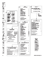
s1
Two-Band Calibration Procedure for
8510XF Performance Verification
Clarifying Connector Sex:
The calibration standard labels that appear in the 8510XF softkey
calibration menus specify connector sex as "(M)" or "(F)". The sex designator
refers to the sex of the test port connector to which the calibration standard
is connected (not the sex of the calibration standard connector).
The 8510XF requires separate verifications for frequencies below
and above 50 GHz (see "Frequency Ranges" in this same chapter).
E7341A
(Std. or
Opt. 005)
8510C
A special two-band calibration procedure is required for the
performance verification of the 8510XF System (a single full-band
measurement calibration is not equivalent).
There are up to three different full 2-port calibrations and
corresponding frequency ranges required, which are stored
in suggested locations in the 8510 analyzer.
MM Controller
Offset Shorts:
Offset shorts are used in the place of opens and loads at frequencies above 50 GHz.
The "OPEN" category is therefore renamed "OPEN/SHORT," and the "LOAD"
category is renamed "LOAD/SHORT" on the calibration menu softkey labels.
Male Test Port
Female Calibration Standard
Left
Test
Head
(E7352L or
E7342L)
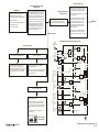
Calibration Storage Locations
Right
Test
Head
(E7352R or
E7342R)
83651B
Open/Short
83621B
File Location Name:
Frequency Range of Data Stored:
Cable
F-F (8.8 cm)
1–50 GHz 1 (2–50 GHz)2
Cal Set 1
Full 2-Port
Reflection
Cal Menu
1
Cal Set 2
45 MHz
Cal Set 3
50–110 GHz 3
Full 2-port calibration system configuration
for performance verification in 1.0 mm coax.
1. This calibration is for Option 005 systems only.
2. The frequency for standard systems is 2–50 GHz.
3. The frequency range shown is for the E7352A system only.
The E7342A system's frequency range will be: 50–85 GHz
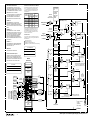
(S11):
OPEN/SHORT
CLASS11A
SHORTS
CLASS11B
LOAD/SHORT
CLASS11C
(S22):
OPEN/SHORT
CLASS22A
SHORTS
CLASS22B
LOAD/SHORT
CLASS22C
(F) OPEN
(M)
(F) SHORT3
(M)
(M) OPEN
(F)
(M) SHORT3
(F)
DONE
OPEN/SHORT
DONE
Cable F-F (8.8 cm) 11500-60001
From 85059A calibration verification kit
Shorts Menu
For more information refer to the section on "Frequency Ranges"
in this same chapter. The parameters for these calibrations are set up
automatically on the analyzer by the performance verification software.
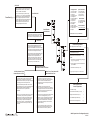
Full 2-Port
Cal Menu
REFLECT'N
REFL
TRANSMISSION
TRAN
ISOLATION
Frequency
Range
Calibration
Technique
DC–50 GHz 3
SOLT
50–110 GHz
Full 2-Port
Transmission
Cal Menu
FWDT
Calibration Techniques and Standards
FWD. MATCH
THRU
FWDM
Calibration Kit Label: 1.00mmA.1A
Disk File Name: CK_MMKA1A
REV. TRANS.
THRU
REVT
REV. MATCH
THRU
REVM
TRANS.
DONE
TRAD
"Short" Standard
(Reflection)
"Load" Standard
(Reflection)
"Thru" Standard
(not used for
1-port cal)
"Isolation"
Standard
Open
Short 3
50 GHz Load
Thru
50 GHz Load
Short 1
Short 4
Short 2
Offset Shorts
ISOL
REFD
FWD. TRANS
THRU
"Open" Standard
(Reflection)
1
REFLECT'N
DONE
SAVE
2-PORT CAL
Short 3
1. SOLT = Short, Open, Load and Thru standards
2. The broadband load is a combination of a lossy delay line plus a 50 GHz load.
Thru
Load BB
(F) SHORT3
(M)
(F) SHORT1
(M)
(M) SHORT3
(F)
(M) SHORT1
(F)
DONE
SHORTS
DONE
SAV2
Load/Short
Menu
2
Cal
Cal Set
Select Menu
(F)
(M)
50 GHz LOAD
Full 2-Port
Isolation
Cal Menu
(F) SHORT4
(M)
(F) SHORT2
(M)
(M) SHORT4
(F)
(M) SHORT2
(F)
3. Also used for 45 MHz frequency point.
OMIT
ISOLATION
OMII
Calibration Techniques:
FWD ISOL'N
LOAD
FWDI
• SOLT (Short-Open-Load-Thru) Used for performance verification 45 MHz to 50 GHz.
• Offset Shorts (Shorts with different offset lengths) Used for performance verification 50 GHz
REV ISOL'N
LOAD
REVI
to 110 GHz.
• TRL (Thru-Reflect-Line)**
• TRM (Thru-Reflect-Match)**
ISOLATION
DONE
A variety of calibration techniques can be used with the 8510XF, including the following:
** Note: Not used for performance verification
The calibration technique used depends in part on the type of calibration kit used. The 1.0 mm
calibration kit (85059A) was designed specifically for the 8510XF, and uses a combination of
two calibration techniques: SOLT calibration for frequencies up to 50 GHz, and offset shorts
calibration for frequencies above 50 GHz. This combination of techniques provides the best
possible calibration results on the 8510XF.
rr51c
(F)
(M)
(F)
DONE
LOAD/SHORT
(M)
(F)
Lossy Delay Line
DONE
(M)
50 GHz Load
ISOD
"FWD/REV ISOL'N LOAD"
For: < 50 GHz use a 50 GHz load only.
For: > 50 GHz a lossy delay line is required in addition
to a 50 GHz load.*
* Note: If you use a 50 GHz load only, a bad calibration will
result due to reflection from the load above 50 GHz.
8510XF Full 2-Port Calibration Menus
5
System Level Servicing & Troubleshooting
This chapter describes the basic servicing and troubleshooting techniques for
the 8510XF system.
8510XF Service Quick Reference Guide 5-1
System Level Servicing & Troubleshooting
Theory of Operation
Theory of Operation
The 8510XF applies RF test signals to the DUT, and compares these incident
signals to whatever is reflected from (or transmitted through) the DUT. The
incident, reflected, and transmitted signals are separated out by means of
directional couplers, and mixed down to create a set of four IF inputs to the
analyzer, as illustrated below.
Figure 5-1
Basic operation of the system
5-2 8510XF Service Quick Reference Guide
System Level Servicing & Troubleshooting
Theory of Operation
At this simplified level of description, system operation does not differ from
that of other 8510-based systems. What makes the 8510XF unique is the
means by which it covers its extremely wide frequency range.
Figure 5-2 shows how the 8510XF test set is divided into frequency bands.
For the sake of simplicity, this figure only shows half of the test set. An
actual test set, with two base units and two test heads, would include twice
as many mixers. Note that all bands make use of the same output/input
paths, the same connection to the DUT, and the same directional couplers.
Figure 5-2
Modules of the 7352A test set
8510XF Service Quick Reference Guide 5-3
System Level Servicing & Troubleshooting
Theory of Operation
Millimeter Wave
Controller
The controller has more functions than are illustrated in Figure 5-2 on
page 5-3. It controls the switching of RF paths in the microwave subheads
and test heads at different points in the system’s frequency range. It also
collects together the IFs generated by all mixers in the microwave subhead,
the millimeter test heads, and the controller itself, and uses a multiplexer to
furnish the appropriate IFs to the network analyzer at each moment in time.
Frequency Bands
Each frequency band uses its own set of mixers. The bands are as follows.
Band
Included In
.045 to 2 GHz
8510XF systems with Option 005
2 to 50 GHz
All 8510XF systems
50 to 85 GHz
50 to 75 GHz
E7340A systems/E7342A subsystems
E7350A systems/E7352A subsystems
75 to 110 GHZ
E7350A systems/E7352A subsystems
Frequency Multiplication
The frequency range of the system greatly exceeds that of the system’s RF
source (the 83651B has a maximum frequency of 50 GHz). Frequencies
above 50 GHz are generated through harmonic multiplication of the RF
source. The signals from the LO source are also multiplied, in the sense that
the mixers in certain ranges are designed to use a harmonic of the LO input,
rather than the fundamental input. The details for each band are discussed
below.
75 to 110 GHz Band
In the 75 to 110 GHz range, the signal from the RF source is applied to a
frequency tripler in the test head. The mixers for this range are located in the
test head, and designed to use the 18th harmonic of the LO input frequency.
This applies to E7350A systems and E7352A subsystems only.
50 to 85 GHz or
50 to 75 GHz Band
In the 50 to 85 GHz range, the signal from the RF source is applied to a
frequency doubler in the test head. The mixers for this range are located in
the test head, and designed to use the 14th harmonic of the LO input
frequency. For E7350A systems and E7352A subsystems, this band covers
the 50 to 75 GHz range.
2 to 50 GHz Band
In the 2 to 50 GHz range, the signal from the RF is not multiplied; it is
applied directly to the mixers. The mixers for this range are located in the
microwave subhead. In a portion of this range (from 18 to 50 GHz) the
mixers use the third harmonic of the LO input frequency. In the remainder of
this range (from 2 to 18 GHz), the mixers use the fundamental of the LO
input frequency.
5-4 8510XF Service Quick Reference Guide
System Level Servicing & Troubleshooting
Theory of Operation
0.045 to 2 GHz Band
In the .045 to 2 GHz range, the signal from the RF source is not multiplied; it
is applied directly to the mixers. The mixers for this range are located in the
millimeter wave controller, and are designed to use the fundamental of the
LO input frequency. This applies to 8510XF systems equipped with
Option 005 only.
8510XF Service Quick Reference Guide 5-5
System Level Servicing & Troubleshooting
8510XF Firmware Specifications
8510XF Firmware Specifications
Operating Parameters
Frequency Limits: 45 MHz to 85 GHz (E7340A/E7342A with Option 005)
or 45 MHz to 110 GHz (E7350A/E7352A with Option 005)
Band Crossings:
Table 5-1
Table 5-2
Step Mode
Band crossings (45 MHz- 85 GHz)
RF Frequency
RF Harm
LO Harm
Band
45 MHz - 2 GHz
1
1
0
2 - 18 GHz
1
1
1
18 - 50 GHz
1
3
1
50 - 64.2 GHz
2
12
2
64.2 - 85 GHz
2
14
2
Band crossings (45 MHz- 110 GHz)
RF Frequency
RF Harm
LO Harm
Band
45 MHz - 2 GHz
1
1
0
2 - 18 GHz
1
1
1
18 - 50 GHz
1
3
1
50 - 64.2 GHz
2
12
2
64.2 - 75 GHz
2
14
2
75 - 85.5 GHz
3
14
3
85.5 - 97.7 GHz
3
16
3
97.7 - 110 GHz
3
18
3
Internally implemented as frequency list mode.
•
•
•
•
•
List Mode
51 points
101 points
201 points
401 points
801 points
Up to 801 points.
5-6 8510XF Service Quick Reference Guide
System Level Servicing & Troubleshooting
8510XF Firmware Specifications
Sweep Time
Hardware States
Similar to 8510C.
The hardware states specific to the 8510XF are as shown in Table 5-3.
Table 5-3
Hardware States Specific to 8510XF
System Parameter
Frequency Range
(45 MHz to 50 GHz)
Frequency Range
(50 to 85 GHz, or 50 to 110 GHz)
System Phaselock1
None
None
Multi Source1
On
On
Leveling Source #1 (RF)2
System (External)
System (External)
Leveling Source #22
System (Internal)
System (Internal)
1. These menus are integrated into the firmware and are not available as softkeys.
2. Source leveling is set to system for normal (default) 8510XF operation. The source will indicate
external leveling for the RF source and internal leveling for the LO source.
Receiver: Constant frequency = 0.020000000 GHz
Instrument States
Table 5-4
Table 5-4 shows the instrument states specific to the 8510XF system.
Instrument states specific to the 8510XF system
System Parameter
Frequency Range
(45 MHz to 50 GHz)
Frequency Range
(50 to 85 GHz or
50 to 110 GHz)
RF Power source #11,2
−10 dBm
−10 dBm
LO Power source #21,2
+10 dBm
+10 dBm
Zo
50 ohm
50 ohm3
Delay
Coaxial
Coaxial
1. The 8510XF normally operates in step mode (ramp mode is not available).
2. Source power is set/read with internal source leveling selected. Normal (default) operation of the 8510XF is with
system source leveling selected.
3. Zo is normally set to one Ohm for calibrations/measurements using waveguide test port connectors.
8510XF Service Quick Reference Guide 5-7
System Level Servicing & Troubleshooting
Power Level Check
Power Level Check
A quick operational check may be performed by measuring the power levels
of the 8510XF user parameters a1, b1, a2, and b2. Observing the appropriate
levels listed in Table 5-5 on page 5-9 gives the user a high level of
confidence that the system is operating properly. For complete system
verification, see Performance Verification, page 4-1.
1. If needed, save the current instrument state by pressing INSTRUMENT STATE
[SAVE] and selecting 1-8. Press INSTRUMENT STATE [RECALL], {MORE}, {FACTORY
PRESET} to restore the default factory instrument state. Change the
instrument settings as indicated under “Power level check (low RF
power)” on page 5-10.
2. Connect a short to test port 1. Press PARAMETER [MENU], then {USER 1 a1}.
The forward reference signal path power level is displayed. The power
level should be approximately as indicated in Table 5-5 and Figure 5-3
on page 5-11.
3. Select {USER 4 b1}. The forward reflection signal path power level is
displayed. The power level should be approximately as indicated in
Table 5-5 and Figure 5-6 on page 5-12.
4. Connect a short to test port 1. In order to measure the reverse reference
signal path, the parameter must be redefined. Press:
{USER 3 a2}
{REDEFINE PARAMETERS}
{DRIVE} {DRIVE:PORT2}
{REDEFINE DONE}
The reverse reference signal path signal level is displayed. The power
level should be approximately as indicated in Table 5-5 and Figure 5-5
on page 5-12.
5. In order to measure the reverse reflection signal path, the parameter
must be redefined. Press:
{USER 2 b2}
{REDEFINE PARAMETERS}
{DRIVE} {DRIVE:PORT2}
{REDEFINE DONE}
The reverse reflection signal path power level is displayed. The power
level should be approximately as indicated in Table 5-5 and Figure 5-4
on page 5-11.
5-8 8510XF Service Quick Reference Guide
System Level Servicing & Troubleshooting
Power Level Check
6. Connect Port 1 and Port 2 together. Select {USER 2 b2} {REDEFINE
PARAMETERS} {DRIVE} {DRIVE:PORT1}. The forward transmission signal path
power level is displayed. The power level should be approximately 2 dB
less than what was measured with a short on each test port.
NOTE
The following measurements show the approximate RF signal levels
incident at the first frequency conversion stage and are given in dBm even
though the marker value is read out in dB.
NOTE
Figures 5-3 through 5-6 are typical graphs from which the data in Table 5-5
was derived. These graphs are typical 8510XF user channel traces with
offset shorts connected to Port 1 and Port 2. The RF source power level must
be set so that it does not activate the IF OVERLOAD running error message.
Table 5-5
Typical power levels for power level check (low RF power) of the mm-wave
sub-system
Raw Channel Power
NOTE
Frequency Range (GHz)
0.045 to 50
Frequency Range (GHz)
50 to 85 (E7340A/E7342A)
50 to 75 (E7350A/E7352A)
Frequency Range (GHz)
75-110 (E7350A/E7352A only)
a1 (USER 1)
−5 to −35
−30 to −50
−35 to −50
b1 (USER 4)
−5 to −35
−30 to −50
−35 to −50
a2 (USER 3)
−5 to −35
−30 to −50
−35 to −50
b2 (USER 2)
−5 to −35
−30 to −50
−35 to −50
0.1 dB compression, −8 dBm; typical, −10 dBm maximum; damage,
+15 dBm.
If any of the power levels shown in Table 5-5 and Figures 5-3 through 5-6
are not observed (within approximately ±5 dB), consult the “Service and
Troubleshooting” paragraphs in this Quick Reference Guide. An Agilent
Customer Engineer may be contacted for service assistance (see “Contacting
Agilent” on page v).
Additional graphs—for help with troubleshooting—are provided in the
following sections:
•
•
“Power level check (high RF power)” on page 5-13
“Operator’s check (normal operating condition)” on page 5-16
8510XF Service Quick Reference Guide 5-9
System Level Servicing & Troubleshooting
Power Level Check
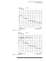
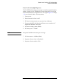
Test Plots
Power level check (low RF power)
The RF source power level must be set so that the IF OVERLOAD running
error message is not activated when obtaining these graphs. The graphs
Figures 5-3 through 5-6 were obtained with the following settings:
1. Factory preset
2. Shorts connected to Ports 1 and 2
3. RF Source leveling: internal (no conversion loss calibration)
4. Disconnect the BNC cable from the millimeter-wave controller ALC
output to the RF Source ALC input.
5. LO Source leveling: system (default)
6. RF Source power: −10 dBm (default)
NOTE
In order for no IF OVERLOAD running error message to occur, it may be
necessary to set the RF Source power level lower.
7. LO Source power: +10 dBm (default)
8. Response reference value: 0 dB (default)
9. Response reference position: 8 Div
5-10 8510XF Service Quick Reference Guide
System Level Servicing & Troubleshooting
Power Level Check
Figure 5-3
User 1 (a1)
Figure 5-4
User 2 (b2)
8510XF Service Quick Reference Guide 5-11
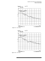
System Level Servicing & Troubleshooting
Power Level Check
Figure 5-5
User 3 (a2)
Figure 5-6
User 4 (b1)
5-12 8510XF Service Quick Reference Guide
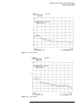
System Level Servicing & Troubleshooting
Power Level Check
Power level check (high RF power)
The IF OVERLOAD running error message is normal when obtaining these
graphs. A power level of +10 dBm will over drive the 8510XF so you can
see the intermodulation leveling differences. The graphs Figures 5-7 through
5-10 were obtained with the following settings:
1. Factory preset
2. Shorts connected to Ports 1 and 2
3. RF Source leveling: internal (no conversion loss calibration)
4. Disconnect the BNC cable from the millimeter-wave controller ALC
output to the RF Source ALC input.
5. LO Source leveling: system (default)
6. RF Source power: +10 dBm
NOTE
Disregard IF OVERLOAD running error message.
7. LO Source power: +10 dBm (default)
8. Response reference value: 0 dB (default)
9. Response reference position: 8 Div
8510XF Service Quick Reference Guide 5-13
System Level Servicing & Troubleshooting
Power Level Check
Figure 5-7
User 1 (a1)
Figure 5-8
User 2 (b2)
5-14 8510XF Service Quick Reference Guide
System Level Servicing & Troubleshooting
Power Level Check
Figure 5-9
User 3 (a2)
Figure 5-10
User 4 (b1)
8510XF Service Quick Reference Guide 5-15
System Level Servicing & Troubleshooting
Power Level Check
Operator’s check (normal operating condition)
The graphs Figures 5-11 through 5-14 were obtained with the following
settings (normal default settings) after performing a factory preset:
1. Shorts connected to Ports 1 and 2
2. RF Source leveling: system (default—with conversion loss calibration)
3. BNC cable connected from millimeter-wave controller ALC output to
the RF source ALC input (default).
4. LO Source leveling: system (default)
5. Port 1 and Port 2 power level: −15 dBm (default)
6. Response reference value: −20 dB
7. Response reference position: 5 Div (default)
NOTE
For additional information on normal operating conditions, refer to the
“System Operation Test” section in the “Installation” chapter of the 8510XF
Operating and Service Manual.
5-16 8510XF Service Quick Reference Guide
System Level Servicing & Troubleshooting
Power Level Check
Figure 5-11
User 1 (a1)
Figure 5-12
User 2 (b2)
8510XF Service Quick Reference Guide 5-17
System Level Servicing & Troubleshooting
Power Level Check
Figure 5-13
User 3 (a2)
Figure 5-14
User 4 (b1)
5-18 8510XF Service Quick Reference Guide
No Obvious Failure Type
Do a Pre-Operational Check of the
8510XF System
What's Wrong?
1. Do you have any self test failures, running error
messages (beeping) or raw channel power
(unratioed power) problems? = MAGIC QUESTION.
Check Front and Rear Panel control settings, cables and
GPIB addresses. Check the 85101 free run switch
on the A5 Processor Board (all zeros), and proper firmware revisions for source and 8510XF (you may need
to reload the Operating System in an extreme case).
Check that the 8510XF firmware is XF.01.00 or greater.
2. Failed performance tests?
3. Display or Front Panel abnormalities, measurement
errors, or display hang-ups?
4. Low or no power symptoms?
First, turn on the Sources, then the Test Set, then the
8510XF, or the system cabinet power switch. Then
check all troubleshooting LED's. See the 8510XF
system level troubleshooting block diagram for these
LED's. See installation for additional information in
performing the Preflight Checkout.
The best approach to repair the 8510XF at this point
is to verify that the 85101C is good. Once it is known
to be good, it will act as your diagnostic controller.
If NO Obvious Failure Type
Prove 85101 is OK
Remove the external controller, printer, etc. and the cables
from the 8510XF system.
Run the 8510XF Service Program to verify that the
8510XF is OK to a 95% confidence level. To do this,
run all the service program tests in the "85101C
Display/Processor Service Program menu (#1)."
These tests take about ten minutes. Refer to the
8510XF Service Program Flowchart. See partial
flowchart on next page.
Obvious Self-Test, running error, or unratioed power test
failure. Refer to the 8510XF Service Manual, part
number E7350-90001, Service and Troubleshooting.
To Sheet 2
NOTE: the above tests can be skipped if the 85101C
passes the power up 85101 self test. The self test
has only a 70% confidence level, so use it accordingly.
Obvious Failure Type
Simplified Signal Path of Unratioed Power Level Tests
83621A/B
LO Source
45 MHz to 20 GHz
Test Head ( 1 of 2 )
Obvious Failure Type
75-110 GHz
X3
Obvious Calibration or Verification Problem
Obvious Software Problem
83651A/B
RF Source
45 MHz to 50 GHz
PREAMP
Millimeter
Wave
Controller
SLOPE AMP
50 GHz110 GHz
PREAMP
8-18 dB
50-75 GHz
X2
Combiner
Splitter r
45 MHz - 110 GHz
<50 GHz
Option 005
IF
EPROM ID on the
GPIB Board A12
It might be a known software bug. See STARS bug report.
Call the factory with details for checkout and duplication
of unknown and new bugs!
Obvious Power Supply Problem
L
IF
I
LO
L
IF
IF, 2-50 GHz
Band
I
L
IF
I
RF
R
2-50 GHz
Splitter
RF
<2 GHz
LO
Refer to Qualified
Personnel Only!
E7340
flowcht1.cdr
Rev. 2 4/22/98
Test IFs
I
LO
L
IF
IF, 2-50 GHz
Band
I
L
RF
(Reflected or
Transmitted)
test b1, b2
3t
RF
R
50-75 GHz
Combiner
Splitter
t
2t
RF
R
75-110 GHz
R
L
IF
IF, 50-75 GHz
Band
I
RF
(Incident)
a1, a2
4t
RF
L
LO
IF
Combiner
Splitter r
1r
IF, 75-110 GHz
Band
IF, 45 MHz-2 GHz
Band
Option 005
50-75 GHz
<50 GHz
I
The 85102 power switch LED is supplied by the +5V
supply in the 85101.
RF
R
r
R
LO
3r
2r
IF
CHECK POWER SUPPLIES
75-110 GHz
R
LO
IF, 50-75 GHz
Band
IF, 45 MHz-2 GHz
Band
Option 005
RF
L
I
IF, 75-110 GHz
Band
LO
Check all main (110V/220V) fuses and power switches.
Remove 85101, 85102 and E7342A/52A instrument
covers and check LED power and service indicator lights.
Recheck by measuring each power supply voltage with a
DVM.
SLOPE AMP
LO
4r
Try the backup standard software by reloading the
Operating System firmware.
Reference IFs
Read the 8510XF Calibration and Verification and
Cable manuals on how to inspect, gage, clean, and
use the calibration and verification devices, waveguide,
and test port return cables. Make sure, if your 85059A
Verification Kit has been certified to 110 GHz within the
past year.
45 MHz50 GHz
Splitter
2-50 GHz
<50 GHz
t
1t
RF
<2 GHz
R
Microwave Subassembly
Millimeter Wave Subassembly
45 MHz to
2 GHz
Test Port
( 1 of 2)
8510XF System Service Flow Diagram (Sheet 1of 2)
5-17/5-18
85101 is OK
Main Service Functions Menu
NOTE: From this point, the problem is probably one of the
remaining instruments; the 85102, sources, test heads,
the mm-wave controller or their interfaces.
From Sheet 1
You can use the 8510XF, power-up self tests, running
error messages, a1, a2, b1, and b2 raw channel displays,
troubleshooting LED's, and passed installation data and
displays to help pinpoint the problem to an instrument.
But, with the diagnostic aids that are now available for the
8510XF, the quickest way to isolate a problem to an
instrument is using the technique of instrument substitution using the diagnostic aids as follows:
Looping Self Tests
Prove 85102 is OK
GPIB
GPIB
To prove that the 85102 is OK, run the built-in 85102
IF/Detector Service Program Number 2. This verifies that
the 85102 is good to an 80% confidence level. It takes
less than a minute to run and pinpoint failures to a board.
Partial Flowchart
Quick Reference
1
2
3
4
5
6
7
8
9
10
11
12
13
14
A5 Processor Eprom
A5 Processor Ram
A7 Data Bus
A4 Display Processor
A4 Display Ram
A7 Timer/Clock/RS-232
A7 Public HP-IB
A7 System Bus
Interrupt System
A5 Multiplier
A7 Disk Controller
A6 Non-Volatile Memory
IF Detector Data
Keyboard
System Commands
15
16
17
18
Run Main Program
Memory Operations
Rerun Self Test
Repeat Test Loop
Disk Commands
19 Load Program Disk
20 Record Program Disk
21 Initialize Disk
Service Commands
22 Run Service Program
23 Diagnose a Failure
ENTER selection, then press =MARKER
85102 is OK
(20 minute test)
To prove that the E7342A/52A Millimeter Sub-Systems
are at fault use the part number 85102-60210 5-way
power splitter. This substitutes for the mm-wave controller
test heads and sources and proves whether they are at fault.
Also run the 8510C Service Program Menu number 3.
8510 Service Program Menu
85101 Display/Processor Service Program
1
85102 IF/Dectector Service Program
2
Test Set GPIB Service Program
Finally, perform the RF Source built-in diagnostics and the
E7342A/52A un-ratioed power troubleshooting. Refer
to the Operator's Check , and perform this check to
troubleshoot the un-ratioed power levels. This tests the
RF Sources mm-wave controller and test heads. This
verifies that the RF Source, mm-wave controller and test
heads are operating to a 90% confidence level.
Return to Main Service Functions Menu
3
F[,]
NOTES:
1. Hex digits A thru F are assigned to [G/n], [M/u], [k/m],
[X1], [+/-], and [.] respectively.
2. To make a selection, type the number indicated, then
press =MARKER.
If All Four Channels are OK,
the 8510XF is OK and You are Done!
If All Four Channels Fail the
Unratioed Power Level Tests
If all four channels fail the Unratioed Power Level Tests,
the most likely causes are a failure in the RF or LO Sources
signal going to the Controller test head and associated
cables that effect all four channels (see LO path and RF path).
A Power Supply can also cause these paths to fail.
Remove the GPIB and RF power cables from the 8510XF
system to isolate the sources. Refer to the appropriate source
manual to troubleshoot the 83651B and 83621B. For
8360 series sources use the front panel emulator
08510-60022.
NOTE: Do not try to measure the RF source power in source
#1 in the 8510XF system by disconnecting the RF cable.
Measuring the RF from the source breaks the leveling loop
and causes the source to supply maximum power output.
Instead, try placing a coupler in the RF cable path and
measure the power that way. Consider substituting known
good sources and cables for the suspected sources, if they
are available.
If One, Two, or Three Channels Fail
the Unratioed Power Tests
If One, Two, or Three Channels Fail the Unratioed Power Tests.
If the power levels on at least one but not all of the four
channels fail, the most likely cause of failure is the test head
or mm-wave Controller. See E7342A/52A manual for
service procedures for they are manual procedures and cannot be abbreviated here.
Below describes how test set manual works for the
8510XF. To help narrow the problem to the faulty instrument,
the service adapter and service tools are used to emulate the
operation of the source and test set and check unratioed
power levels into the 85102 IF/Detector.
Run the Service Program using the Test Set GPIB commands
tests. These tests can find approximately 15% of all
E7342A/52A mm-wave Controller failures and requires about
one minute to complete. The digital functionality of the mmwave Controller is checked with this test, not the RF paths.
Finally, use the failed unratioed power test to find the bad
path/paths and assembly.
3. The default value on data entry is zero.
copyright © Agilent Technologies 1987, 1988, 1990, 1998, 2000
85101 Display/Processor
Service Program Menu
CPU Board Tests (A5)
1
I/O Board and Front Panel Tests (A1, A2, A7)
2
Display Board and CRT Tests (A4, A11)
3
Non-Volatile Memory Board Tests (A6)
4
Return to 8510 Service Program Menu
F [,]
NOTE: Do not perform Test number 5 "Increment Active
Attenuator" in the "Test Set GPIB Commands" menu. The
mm-wave Controller does not contain any attenuators.
E7340
flowcht2.cdr
Rev. 2 4/22/98
8510XF System Service Flow Diagram (Sheet 2of2)
5-19/5-20
HOW TO READ THIS BLOCK DIAGRAM:
Self Test Indicators for Millimeter Wave Controller GPIB Board
THIS DIAGRAM SHOWS A TYPICAL 851OXF SYSTEM
CONFIGURATION. NOTE THAT THE CIRCUIT BOARDS AND
ASSEMBLIES HAVE NUMBERS PRECEDED BY THE LETTER
'A', THAT NUMBER IDENTIFIES THE ASSEMBLY. THE OTHER
NUMBERS REFER TO THE LIST ON SHEET 2.
If the ACTIVE LED on the Front Panel does not light within two seconds
of turn on, or lights immediately, the test has not passed it’s Self Test.
You can determine what part of the Self Test failed by determining which
GPIB LEDs on the A12 Assembly are lit. The Table below shows the
possible Self Test failures.
USE THIS BLOCK DIAGRAM AS A QUICK REFERENCE GUIDE
TO SYSTEM FAILURES AS WELL AS A GUIDE TO LED
LOCATION AND MEANING. TEST SET ADDRESS AND
CONFIGURATION SWITCH SETTINGS ARE ALSO SHOWN.
NUMBERS 1 – 14
THESE NUMBERS IDENTIFY THE SELF TEST THAT
EXERCISES THE PARTICULAR ASSEMBLY, MOSTLY ON THE
85101 DISPLAY/PROCESSOR. FOR MORE INFORMATION,
REFER TO 'SELF' TEST FAILURES IN THE ON – SITE SERVICE
MANUAL.
NUMBERS 15 – 36
THESE NUMBERS IDENTIFY THE BUILT – IN RUNNING
ERROR MESSAGE THAT WILL APPEAR ON THE 8510I CRT IF
A SYSTEM FAILURE IS DETECTED. MOSTLY ON THE 85102
IF/DETECTOR, TEST SET, AND SOURCE. THE NUMBERS
IDENTIFY THE ASSEMBLIES WHERE THE ERROR IS
DETECTED OR GENERATED. FOR MORE INFORMATION,
REFER TO 'RUNNING ERROR MESSAGES' IN THE ON – SITE
SERVICE MANUAL.
NUMBERS 37 – 41
THESE NUMBERS IDENTIFY RUNNING ERROR MESSAGES
ASSOCIATED WITH 8360 – SERIES SOURCES ONLY AND
APPEAR ON THE 85101 CRT.
Self Test
Indication
A12 GPIB LEDs
LSN
TLK
SRQ
Elapsed Time
After Turn-On
REM (in seconds)
PWON
ON
ON
ON
ON
0 to 0.5
Fail ROM Test
OFF
ON
ON
ON
ON Briefly
Pass ROM Test
OFF
OFF
ON
ON
0.52 to 2.0
Fail RAM Test
OFF
OFF
OFF
ON
Pass RAM Test
OFF
OFF
OFF
OFF
83621A/B
LO Source
45 MHz to 20 GHz
Test Head ( 1 of 2 )
75-110 GHz
GPIB System Bus
X3
10 MHz REF
After 2 sec.
83651A/B
RF Source
45 MHz to 50 GHz
Two seconds after turn-on all four GPIB LEDs should go OFF, and the
Front Panel ACTIVE LED should light simultaneously. After going out
briefly, the two GPIB LEDs will light according to the state of the Test
Set. If you are using multiple Test Sets, the first Test Set in line will be
the active Test Set until another is chosen.
If the portion of memory which contains the Self Test programming is faulty,
the Self Test will not run properly. The following conditions indicate that the
Self Test ROMs are faulty:
All LEDs flash briefly and go OFF
All LEDs flash briefly and stay ON
ACTIVE LED goes ON before GPIB LEDs go OUT
ACTIVE LED does not go ON at all (check LED operation before proceeding)
Option 005
8 in-lbs
20 mm
8710-1764
8 in-lbs
5/16 in
8710-1765
4 in-lbs
6 mm
8710-2079
IF, 75-110 GHz
Band
IF, 50-75 GHz
Band
8510XF
(Rear View)
IF
IF, 45 MHz-2 GHz
Band
Option 005
I
L
IF
I
L
IF
I
40104A Rack
Filler Panel
10 MHz In
8510C Interconnect
Option 006
Coupled RF Output
RF
Splitter
2-50 GHz
RF
<2 GHz
LO
IF
L
IF
I
L
I
GPIB
LO
75-110 GHz
3t
RF
R
RF
(Reflected or
Transmitted)
test b1, b2
Combiner
Splitter
50-75 GHz
t
2t
RF
R
4t
R
LO
IF
RF
(Incident)
reference a1, a2
DS7 and DS9 LEDs (Yellow)
45 MHz to 50 GHz Both ON DS7 and DS9
50 GHz to 75 GHz DS7 OFF DS9 ON
75 GHz to 110 GHz DS9 OFF DS7 ON
RF
L
I
IF, 75-110 GHz
Band
IF, 2-50 GHz
Band
Combiner
Splitter r
<50 GHz
R
LO
System Bus
50-75 GHz
r
IF, 50-75 GHz
Band
Test Set IF Interconnect
LO Input
RF
R
2r
R
Trigger In
RF Input
MM Wave
Controller
(Address 23)
3r
1r
Test Set Interconnect
85102B
L
IF
75-110 GHz
R
LO
GPIB Board
4 LEDs
ALLEN WRENCH #6 = 1/16 IN. 5020-0289 (For RPG Knob)
RF
L
I
+5V LED Front
Panel
Power Switch
IF, 2-50 GHz
Band
40103A Rack
Filler Panel
SLOPE AMP
LO
Regulator Board
9 Power Supply
LEDs for ALL
Power Supplies
TORX DRIVER T-10 8710-1623 (For Chassis)
{
45 MHz50 GHz
LO
IF/Display
Interconnect
Combiner
Splitter r
4r
UNIQUE TOOLS
Source
Language SW
set to 111
to allow
programs
to select
language.
50-75 GHz
X2
<50 GHz
10 MHz REF
LO
85101C
(Address 16)
PREAMP
8-18 dB
GPIB System Bus
TEST SET DEFAULT SETTINGS: Option 006.
TORX DRIVER T-15 8710-1622 (For Chassis)
SLOPE AMP
50 MHz110 MHz
If Self Test Fails to Run
THESE ARE EXTRA TROUBLESHOOTING
THE DEFAULT STATE OF THE 8517A/B TEST SETS (TURN
POWER OFF, PULL A4 GPIB BOARD AND TURN POWER
BACK ON) IS TO HAVE ALL SAMPLERS ENABLED, A14'S VTO
BIASED ON, PORT 1 AND 2 ATTENUATORS AT 0dB, AND THE
SWITCH SPLITTER APPLYING RF POWER TO PORT 1.
PREAMP
Millimeter
Wave
Controller
Trigger IN
TORQUE WRENCHES
NUMBERS 42 – 45
When changing
A16:
Save EE PROM
from old A16
leveling DAC
board to retain
calibration
constants.
Splitter
2-50 GHz
<50 GHz
t
1t
10 MHz Ref Input
ALC Output
83651B
RF Source
(Address 19)
Language 111
10 MHz Ref Output
RF Output
System Bus
GPIB
EXTALC In
83621B
LO Source
(Address 18)
Language 111
RF Output
Trigger Output
IF, 45 MHz-2 GHz
Band
Option 005
L
IF
I
RF
45 MHz to
2 GHz
GPIB
<2 GHz
R
Microwave Subassembly
Bias Boards and Power
Supply LEDs for all Power Supplies
Millimeter Wave Subassembly
+/- 7 Volt ON LED Front Panel
System Bus
40102A Rack
Filler Panel
46298M
Drawer Unit
10 MHz Ref Output
- Test Port
* Connector
1mm M/F
(part number
85104 - 60061)
GPIB System Bus
Test Port
( 1 of 2)
*
9
To Sheet 2
rr52c
8510XF System Level Troubleshooting Block Diagram (CRT/LCD) (Sheet 1 of 2)
SELF TESTS
1. A5 PROCESSOR EPROM (self test and service program
PROM using checksum)
2. A5 PROCESSOR RAM (test processor memory using data
complement technique)
3. A7 DATA BUS TEST (test I/O data bus)
4. A4 DISPLAY PROCESSOR
5. A4 DISPLAY RAM
6. A7 TIMER/CLOCK/RS – 232
7. A7 PUBLIC GPIB (Read/Write test of GPIB register)
8. A7 SYSTEM BUS (Read/Write) test of system bus register)
9. INTERRUPT SYSTEM (test interrupts)
10. A5 MULTIPLIER (PERFORMS a complex multiply)
11. A7 DISC CONTROLLER
12. A6 NON-VOLATILE MEMORY TEST (read/write test)
13. IF DETECTOR DATA (read/write test data and address lines)
14. KEYBOARD (read 85101C keyboard for a stuck key)
Self Test (1-14), Running Error Messages (15-41), Unratioed Power Test (42), LEDs/GPIB Addresses/Configuration Switch Settings
PC/CONTROLLER
GPIB
System
Bus
GPIB
GPIB
RUNNING ERROR MESSAGES
15. FAILED PRETUNE/LOST PRETUNE
16. NO IF FOUND
17. PHASE LOCK FAILURE
18. PHASE LOCK LOST
19. VTO OVER-RANGE
20. ADC CAL FAILED
21. IF CAL FAILED – REFERENCE;
IF CAL FAILED – TEST;
IF CAL FAILED – BOTH (channels)
22. ADC NOT RESPONDING
23. IF OVERLOAD (External level of 8360 can cause this.)
24. AUTORANGE CAL FAILED
25. SOURCE SLEEP SYNC ERROR
26. SWEEP TIME TOO FAST
27. SOURCE (GPIB) SYNTAX ERROR
28. TEST SET (GPIB) SYNTAX ERROR
29. SYSTEM BUS ADDRESS ERROR
30. SYSTEM BUS SRQ ERROR
31. UNABLE TO LOCK TO EXT 10 MHz REF
32. ERROR: SYSTEM KEY NOT INSTALLED; CAUSED BY SECURITY
KEY MISSING, BAD I/O, BAD A8 CONNECTOR, BAD MOTHER-BOARD.
CAUTION: OPTIONAL FUNCTION: NOT INSTALLED
CAUTION: TIME DOMAIN KEY NOT INSTALLED
33. DISC HARDWARE PROBLEM
34. DISC COMMUNICATION ERROR
35. INITIALIZATION FAILED
36. DISC MEDIA WEARING OUT - REPLACE SOON
(VGA Type
Connector)
85101-60263
MOTHERBOARD
CAPACITORS
69272
69261
B1 FAN
08756-20073
FAN REPLACEMENT KIT
for 85102A
08756-60074
From
Sheet 1
9
7167
8360 – SERIES SOURCES RUNNING ERROR MESSAGES
37. FAILURE – FAULT INDICATOR ON
38. FAILURE – RF UNLOCKED
39. FAILURE – OVERMODULATION
40. FAILURE – SELF TEST FAILURE
41. INVALID SETUP – CHECK SYSTEM BUS CONFIGURATION
0950-3488
A11 DISPLAY SECTION
85102-69272
OTHER TROUBLESHOOTING HINTS
42. Perform the unratioed power test for a1, a2, b1, and b2. Refer to
'System Maintenance, Troubleshooting' in the 8510XF Operating and
Service Manual, E7350-90001.
43. The A4 GSP and the A11 display must be working in order for a normal
display to be on the CRT.
44. If self test 11 passes, try to initialize a blank disc to further test the A2
disc drive.
45. A18 (85102) ANALOG TO DIGITAL CONVERTER TEST
When you first turn the instrument ON, if the noise on the trace is
greater than 1 dB, then the A18 board may be faulty.
If you cycle the AC power (Off, then On), the noise may disappear.
If it does, there is probably a malfunction with the A18 A/D board
although no apparent symptoms are present. There also may be no
Running Error Messages, Self Test Failures or Service Program test
failures.
(In 8510XF for blanking only)
If this trace noise disappears when the POWER is cycled, the test has
FAILED and the A18 board should be REPLACED.
10 MHz REF
Trigger IN
GPIB
NOTE: A16, A23, A22 are not used for
8510XF operation; that is, phase lock
none, except for some signal transfers
from LPTHLD, etc.
rr518c
8510XF System Level Troubleshooting Block Diagram (CRT) (Sheet 2 of 2)
SELF TESTS
1. A5 PROCESSOR EPROM (self test and service program
PROM using checksum)
2. A5 PROCESSOR RAM (test processor memory using data
complement technique)
3. A7 DATA BUS TEST (test I/O data bus)
4. A14 DISPLAY PROCESSOR
5. A14 DISPLAY RAM
6. A7 TIMER/CLOCK/RS – 232
7. A7 PUBLIC GPIB (Read/Write test of GPIB register)
8. A7 SYSTEM BUS (Read/Write test of system bus register)
9. INTERRUPT SYSTEM (test interrupts)
10. A5 MULTIPLIER (PERFORMS a complex multiply)
11. A7 DISC CONTROLLER
12. A6 NON-VOLATILE MEMORY TEST (read/write test)
13. IF DETECTOR DATA (read/write test data and address lines)
14. KEYBOARD (read 85101C keyboard for a stuck key)
Self Test (1-14), Running Error Messages (15-41), Unratioed Power Test (42), LEDs/GPIB Addresses/Configuration Switch Settings
PC/CONTROLLER
GPIB
System
Bus
GPIB
GPIB
RUNNING ERROR MESSAGES
15. FAILED PRETUNE/LOST PRETUNE
16. NO IF FOUND
17. PHASE LOCK FAILURE
18. PHASE LOCK LOST
19. VTO OVER-RANGE
20. ADC CAL FAILED
21. IF CAL FAILED – REFERENCE;
IF CAL FAILED – TEST;
IF CAL FAILED – BOTH (channels)
22. ADC NOT RESPONDING
23. IF OVERLOAD (External level of 8360 can cause this.)
24. AUTORANGE CAL FAILED
25. SOURCE SLEEP SYNC ERROR
26. SWEEP TIME TOO FAST
27. SOURCE (GPIB) SYNTAX ERROR
28. TEST SET (GPIB) SYNTAX ERROR
29. SYSTEM BUS ADDRESS ERROR
30. SYSTEM BUS SRQ ERROR
31. UNABLE TO LOCK TO EXT 10 MHz REF
32. ERROR: SYSTEM KEY NOT INSTALLED; CAUSED BY SECURITY
KEY MISSING, BAD I/O, BAD A8 CONNECTOR, BAD MOTHER-BOARD.
CAUTION: OPTIONAL FUNCTION: NOT INSTALLED
CAUTION: TIME DOMAIN KEY NOT INSTALLED
33. DISC HARDWARE PROBLEM
34. DISC COMMUNICATION ERROR
35. INITIALIZATION FAILED
36. DISC MEDIA WEARING OUT - REPLACE SOON
(VGA Type
Connector)
85101-60263
MOTHERBOARD
CAPACITORS
85101-60298
69272
69261
85101-60300
B1 FAN
08756-20073
FAN REPLACEMENT KIT
for 85102A
08756-60074
From
Sheet 1
9
7167
8360 – SERIES SOURCES RUNNING ERROR MESSAGES
37. FAILURE – FAULT INDICATOR ON
38. FAILURE – RF UNLOCKED
39. FAILURE – OVERMODULATION
40. FAILURE – SELF TEST FAILURE
41. INVALID SETUP – CHECK SYSTEM BUS CONFIGURATION
1
0950-3488
A15 LCD
ASSEMBLY
85101-60297
(Includes A16)
85101-60296
69272
(In 8510XF for blanking only)
10 MHz REF
A16 INVERTER
BOARD
0950-3379
(A16 Only)
OTHER TROUBLESHOOTING HINTS
42. Perform the unratioed power test for a1, a2, b1, and b2. Refer to
'System Maintenance, Troubleshooting' in the 8510XF Operating and
Service Manual, E7350-90001.
43. The A14 GSP and the A15 display must be working in order for a normal
display to be on the LCD.
44. If self test 11 passes, try to initialize a blank disc to further test the A2
disc drive.
45. A18 (85102) ANALOG TO DIGITAL CONVERTER TEST
When you first turn the instrument ON, if the noise on the trace is
greater than 1 dB, then the A18 board may be faulty.
If you cycle the AC power (Off, then On), the noise may disappear.
If it does, there is probably a malfunction with the A18 A/D board
although no apparent symptoms are present. There also may be no
Running Error Messages, Self Test Failures or Service Program test
failures.
If this trace noise disappears when the POWER is cycled, the test has
FAILED and the A18 board should be REPLACED.
Trigger IN
GPIB
NOTE: A16, A23, A22 are not used for
8510XF operation; that is, phase lock
none, except for some signal transfers
from LPTHLD, etc.
rr53c.cdr
8510XF System Level Troubleshooting Block Diagram (LCD) (Sheet 2 of 2)