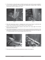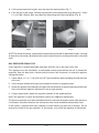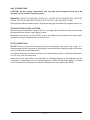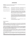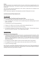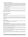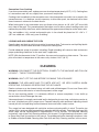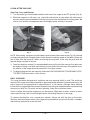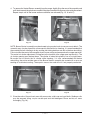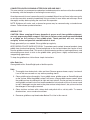
1
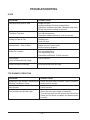
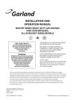
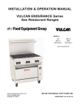
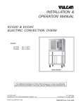
INSTALLATION &
OPERATION MANUAL
ENDURANCE SERIES
GAS RESTAURANT RANGES
MODEL
G36
*G36C
G60
*G60C
G260
*G260C
*Availability to be announced.
G36
For additional information on Vulcan-Hart or to locate an authorized parts
and service provider in your area, visit our website at www.vulcanhart.com
VULCAN-HART
DIVISION OF ITW FOOD EQUIPMENT GROUP, LLC
P.O. BOX 696, LOUISVILLE, KY 40201-0696
TEL. (502) 778-2791
WWW.VULCANHART.COM
FORM 35633 Rev. A (06-05)
IMPORTANT FOR YOUR SAFETY
THIS MANUAL HAS BEEN PREPARED FOR PERSONNEL QUALIFIED TO INSTALL
GAS EQUIPMENT, WHO SHOULD PERFORM THE INITIAL FIELD START-UP AND
ADJUSTMENTS OF THE EQUIPMENT COVERED BY THIS MANUAL.
POST IN A PROMINENT LOCATION THE INSTRUCTIONS TO BE FOLLOWED IN THE
EVENT THE SMELL OF GAS IS DETECTED. THIS INFORMATION CAN BE OBTAINED
FROM THE LOCAL GAS SUPPLIER.
IMPORTANT
IN THE EVENT A GAS ODOR IS DETECTED,
SHUT DOWN UNITS AT MAIN SHUTOFF VALVE
AND CONTACT THE LOCAL GAS COMPANY
OR GAS SUPPLIER FOR SERVICE.
FOR YOUR SAFETY
DO NOT STORE OR USE GASOLINE OR OTHER
FLAMMABLE VAPORS OR LIQUIDS IN THE
VICINITY OF THIS OR ANY OTHER APPLIANCE.
WARNING
IMPROPER INSTALLATION, ADJUSTMENT,
ALTERATION, SERVICE OR MAINTENANCE
CAN CAUSE PROPERTY DAMAGE, INJURY OR
DEATH.
READ THE INSTALLATION,
OPERATING
AND
MAINTENANCE
INSTRUCTIONS THOROUGHLY BEFORE
INSTALLING OR SERVICING THIS EQUIPMENT.
IN THE EVENT OF A POWER FAILURE, DO NOT
ATTEMPT TO OPERATE THIS DEVICE.
© VULCAN-HART, 2005
—2—
INSTALLATION, OPERATION AND CARE OF
ENDURANCE SERIES GAS RESTAURANT RANGES
PLEASE KEEP THIS MANUAL FOR FUTURE USE
GENERAL
Vulcan ranges and ovens are produced with quality workmanship and material. These ranges are
designed with efficiency in cooking performance, sanitation and ease of cleaning ability in mind.
Proper installation, usage and maintenance of your range will result in many years of satisfactory
performance.
The manufacturer suggests that you thoroughly read this entire manual and carefully follow all of
the instructions provided.
OPTIONAL FIELD INSTALLABLE ACCESSORIES
DESCRIPTION
ACCESSORIES
Flue Devices
23" (584 mm) high stainless steel backsplash with plate shelf
23" (584 mm) high stainless steel backsplash with broiler mounting brackets
Stainless steel 11" (279 mm) high riser
Flex Hose and Quick
Disconnect
1" (25 mm) flex hose / disconnect, 4' (1219 mm) long.
Oven Racks
1 extra rack with standard and convection ovens.
Casters
Set of four 6" (152 mm) casters.
INSTALLATION
UNPACKING
This range was inspected before leaving the factory. The transportation company assumes full
responsibility for safe delivery upon acceptance of the shipment. Immediately after unpacking,
check for possible shipping damage. If the range is found to be damaged, save the packaging
material and contact the carrier within 15 days of delivery.
Carefully unpack range(s) and place in the approximate installation position, whether as a battery
or single stand-alone range.
Remove parts (packed in a cardboard box) from oven cavity, or cabinet body, or on top of modular
range(s).
If burner has been shipped using any package strapping devices, remove these before installing
the range.
Before installing, check the electrical service (Convection Oven Models only) and type of gas
supply (natural or propane) to make sure they agree with the specifications on the rating plate
located on the inside of the burner box lower panel. The rating plate will show the voltage, phase,
cycle, full load ampere, BTU, as well as the type of gas. If the supply and equipment requirements
do not agree, do not proceed with the installation. Contact your dealer or Vulcan-Hart immediately.
—3—
LOCATION
The equipment area must be kept free and clear of combustible substances.
Installation clearances (32,000 and 35,000 BTU/hr.):
Back:
COMBUSTIBLE
CONSTRUCTION
6" (152 mm)
NONCOMBUSTIBLE
CONSTRUCTION
0"
Right Side:
10" (254 mm)
0"
Left Side:
10" (254 mm)
0"
The installation location must allow adequate clearances for servicing and proper operation. A
minimum front clearance of 35" (889 mm) is required.
The ranges are suitable for installation on combustible floors when 6" (152 mm) adjustable legs or
casters are used. When legs or casters are removed, use only on noncombustible floors, curb, or
platform, with front appliance projecting 3" (76 mm) beyond curb or platform.
Ranges with convection ovens should be installed on 6" (152 mm) legs or casters, allowing 6" (152 mm)
clearance from the rear of the range.
All modular ranges are to be installed only on non-combustible floors.
The range(s) must be installed so that the flow of combustion and ventilation air will not be
obstructed. Adequate clearance for air openings into the combustion chamber(s) must be provided.
Make sure there is an adequate supply of air in the room to allow for combustion of the gas at the
burners.
INSTALLATION CODES AND STANDARDS
Your Vulcan Range must be installed in accordance with:
In the United States of America:
1. State and local codes.
2. National Fuel Gas Code, ANSI-Z223.1 (latest edition). Copies may be obtained from The
American Gas Association, Inc., 1515 Wilson Blvd., Arlington, VA 22209.
3. National Electrical Code, ANSI/NFPA-70 (latest edition). Copies may be obtained from The
National Fire Protection Association, Batterymarch Park, Quincy, MA 02269.
In Canada:
1. Local codes.
2. CSA B149.1 Natural Gas and Propane Installation Code.
3. CSA C22.1 Canadian Electrical Code.
The above are available from the Canadian Standard Association, 5060 Spectrum Way, Suite 100,
Mississauga, Ontario, Canada L4W 5N6.
—4—
ASSEMBLY
The range is shipped as a complete unit and does not require field assembly.
Bumper Bars (Convection Oven only)
Bumper bars equipped with this unit must be installed. Failure to install bars may result in motor
damage and will void the equipment warranty.
Legs
The range is supplied on 6"(152 mm) adjustable stainless steel legs. (For additional leg information
see Leveling section of this manual).
Casters
Ranges mounted on casters must use a flexible connector
(not supplied by Vulcan) that complies with the Standard for
Connectors for Movable Gas Appliances, ANSI Z21.69 •
CSA 6.16 and a quick-disconnect device that complies with
the Standard for Quick-Disconnect Devices for Use With
Gas Fuel, ANSI-Z21.41 • CSA 6.9. In addition, adequate
means must be provided to limit movement of the appliance
without depending on the connector and the quickdisconnect device or its associated piping to limit appliance
movement. Attach the restraining device at the rear of the
range as shown in Fig. 1.
CONNECT GAS LINE
STRAIN
RELIEF HERE
PL-51219
Fig. 1
If disconnection of the restraint is necessary, turn off the gas supply before disconnection.
Reconnect this restraint prior to turning the gas supply on and returning the range to its installation
position.
Separate instructions for installing casters to the range are included with the casters.
Note: If the range is installed on casters and is moved for any reason, it is recommended that the
range be releveled front to back and side to side for even baking.
—5—
RANGE TOP SECTIONS
1. Remove top grate.
2. Remove burner/venturi/pilot assembly and discard all packing materials in the drip pan basin,
3. Make sure the burner/venturi assembly is in the proper position (Fig. 13, 14 & 15 in this manual).
4. Install all knobs.
GRIDDLE
The range is shipped with the griddle in place for cooking. No farther griddle installation is required,
except for models G260 and G260C with a broiler/griddle.
BROILER GRIDDLE BRICKS
1. Remove six 5 1/4" x 2 1/4" (133 x 57 mm) and six 5 1/4" x 5 1/16 (133 x 129 mm) bricks from the
shipping box packaged in the oven cavity.
2. Install the 5 1/4" x 2 1/4" (133 x 57 mm) bricks to the left and right hand sides of the broiler by
inserting the bricks individually through the front opening in the broiler. Angle the brick sideways
for easy fit between the burner edges. Set the bricks flat in place resting on the broiler side and
burner edges. Push each brick as far to the rear of the broiler as possible to ensure easy fit of
last brick.
3. Install the remaining six 5 1/4" x 5 1/16 (133 x 129 mm) bricks to the center section as described
in step 2. Place the bricks on the center burner edges only.
LEVELING
To level the range, place a carpenter's level on the range top and check leveling of the unit side to
side and front to rear. Achieve leveling by turning each foot section of the unit's leg as needed.
Turning the foot in a counter clockwise direction will increase height and clockwise will decrease
BACKSPLASH/ SHELF
This range is supplied with a standard 23" (584 mm) high backsplasher with a 22" (559 mm) high
mounted plate shelf. To install the backsplasher and plate shelf, follow steps 1 through 9 below.
1. Remove the crating material for the
backsplasher/plate shelf. The backsplasher/
plate shelf is crated resting against the rear
of the range.
2. Remove the entire back row of burner grates
from the range top (Fig. 2).
Fig. 2
—6—
3. Lift backsplash up above the range and slide the channels evenly into the spaces provided at
the rear of the range (Fig. 3). Do not force the backsplasher channels down. Guide the
backsplasher evenly into place until it stops.
Fig. 3
Fig. 4
4. When the backsplasher comes to a stopping point, from the rear of the unit, reach down and
carefully pull the splasher back panel out away from the range (Fig. 4).
5. Resume sliding the backsplasher channels evenly down until it stops again. Do not force
backsplasher channels down.
6. At the second stopping point, move to the front of the range and carefully pull the bottom of the
backsplasher front panel forward. Continue to slide the backsplasher down onto the range until
it is resting squarely over the rear top support channel (Fig. 5 & 6).
Fig. 5
Fig. 6
7. Place the entire row of rear burner grates back in place on the range top.
—7—
8. Lift the plate shelf and hang this onto the top of the backsplasher (Fig. 7).
9. From the rear of the range, secure the plate shelf to the backsplasher by placing four 1/4 x 20 x
2 5/16 (6 x 509 x 59 mm) bolts provided into the existing bolt holes and tighten (Fig. 8).
Fig. 7
Fig. 8
NOTE: For broiler mounting, assemble the backsplasher/plate shelf as described in steps 1 through
9, then follow instructions provided by the broiler manufacturer for mounting the broiler to the plate
shelf.
GAS PRESSURE REGULATOR
A gas regulator is shipped packaged separately with this unit in the oven cavity area.
This regulator must be installed by an authorized service person before the unit is placed into
operation. See unit data plate, riveted inside the lower front kick panel, for pressure regulator
setting information.
1. Locate either a 3/4" or 1" (19 or 25 mm) NPT gas connection pipe protruding through the back
of the unit.
2. Cover the pipe threads with pipe joint compound resistant to propane gases.
3. Screw the regulator onto the pipe hand tight with flow direction arrow pointing towards the back
of the unit and the regulator adjustment in the up right position.
4. Using a pipe wrench, tighten the regulator securely in the upright position.
Note: The regulator is preset and should not require any additional adjustments.
The pressure regulator must be mounted horizontally to ensure the proper preset outlet pressure.
If mounted in any other direction, the outlet pressure must be rechecked and possibly reset.
A leak limiter is supplied with every regulator to allow excess gas pressure to escape. Do not
obstruct the limiter or the gas regulator, as obstruction may cause the regulator to malfunction.
—8—
GAS CONNECTIONS
CAUTION: All gas supply connections and any pipe joint compound used must be
resistant to the action of propane gases.
WARNING: PRIOR TO LIGHTING, CHECK ALL JOINTS IN THE GAS SUPPLY LINE FOR
LEAKS. USE SOAP AND WATER SOLUTION. DO NOT USE AN OPEN FLAME.
After piping has been checked for leaks, all piping receiving gas should be fully purged to remove air.
TESTING THE GAS SUPPLY SYSTEM
When test pressures exceed 1/2 psig (3.45 kPa), the range and its individual shutoff valve must be
disconnected from the gas supply piping system.
When test pressures are 1/2 psig (3.45 kPa) or less, the range must be isolated from the gas supply
system by closing its individual manual shutoff valve.
FLUE CONNECTIONS
DO NOT obstruct the flow of flue gases from the flue located on the rear of the range. It is
recommended that the flue gases be ventilated to the outside of the building through a ventilation
system installed by qualified personnel.
From the termination of the flue to the filters of the hood venting system, a minimum clearance of
18" (457 mm) must be maintained.
Information on the construction and installation of ventilating hoods may be obtained from the
standard for "Vapor Removal from Cooking Equipment," NFPA No. 96 (latest edition), available
from the National Fire Protection Association, Batterymarch Park, Quincy, MA 02269.
—9—
ELECTRICAL CONNECTIONS (CONVECTION OVEN ONLY)
WARNING: ELECTRICAL AND GROUNDING CONNECTIONS MUST COMPLY WITH THE
APPLICABLE PORTIONS OF THE NATIONAL ELECTRICAL CODE AND/OR OTHER LOCAL
ELECTRICAL CODES.
WARNING: DISCONNECT THE ELECTRICAL POWER TO THE MACHINE AND FOLLOW
LOCKOUT / TAGOUT PROCEDURES.
WARNING: APPLIANCES EQUIPPED WITH A FLEXIBLE ELECTRIC SUPPLY CORD ARE
PROVIDED WITH A THREE-PRONG GROUNDING PLUG. IT IS IMPERATIVE THAT THIS
PLUG BE CONNECTED INTO A PROPERLY GROUNDED THREE-PRONG RECEPTACLE.
IF THE RECEPTACLE IS NOT THE PROPER GROUNDING TYPE, CONTACT AN
ELECTRICIAN. DO NOT REMOVE THE GROUNDING PRONG FROM THIS PLUG.
The range is designed for 120 volt power supply or optional 240 volt single phase, 15 amp, 50/60
Hz power supply.
All 120 volt ranges are supplied with a flexible electric supply cord and plug and must be plugged
into the proper receptacle before turning on gas. If the appliance is not equipped with a grounding
plug and electric supply is needed, ground the appliance by using the ground lug provided. All 240
volt electric systems are manufactured for hard wire installation connections. (Refer to the wiring
diagram shipped with this unit in instructional material packet.) An electrical diagram is attached to
the back near the motor mounting area.
Do not connect the range to electrical supply until after gas connections have been made.
— 10 —
OPERATION
WARNING: THE APPLIANCE AND ITS PARTS ARE HOT. USE CARE WHEN OPERATING,
CLEANING OR SERVICING THE APPLIANCE.
CONTROLS
Range Top Burner Valve
— Allows gas to flow to the top burners. To open valve, turn knob
counterclockwise. To close valve, turn knob clockwise.
Yellow Gas Shut-off Valve — Allows gas to flow to the range top. To open valve, turn knob
counterclockwise. To close valve, turn knob clockwise.
Thermostat / Safety Valve — Regulates the oven temperature and pilot safety thermostat.
The thermostat temperature range is from LOW at
approximately 300°F (149°C) to HI at approximately 550°F
(288°C). Turn thermostat clockwise to increase temperature
and counterclockwise to decrease temperature.
NOTE: In P position, pilot remains on. In OFF position, pilot
is extinguished. During shut down and operation, align the
OFF and P positions (as required) of the oven knob with the
tick mark (* or V) indicator on the label or sheet metal located
above the knob. This indicator should also be used as the
temperature set mark.
Fan Switch
— Turns fan on and off.
(Convection Ovens Only - Fan turns ON when door is closed.
Fan turns OFF when door is opened)
BEFORE FIRST USE
Griddles
Griddle tops are shipped with a protective coating of grease. Remove this film only when the griddle
plate is being cleaned prior to its first cooking use. Use a non-corrosive, grease dissolving
commercial cleaner, following manufacturer's directions. Rinse thoroughly and wipe dry with a soft
clean cloth. Clean all accessories. Rinse thoroughly and wipe dry.
Caution: This griddle plate is steel, but the surface is soft and can be scored or dented
by careless use of spatulas or scrappers. Be careful not to dent , scratch or gouge the
plate. Do not try to knock off loose food that may be on the spatula by tapping the
corner edge of the spatula on the griddle surface.
A new griddle surface must be seasoned to do a good cooking job. The metal surface of the griddle
is porous. Food tends to get trapped in these pores and stick. It is important to season the griddle
with cooking oil before using the griddle. Seasoning will give the griddle surface a slick, hard finish
from which food will easily release.
Season the griddle top plate at low setting. Pour one ounce of cooking oil onto the plate per square
foot of the griddle surface. With an insulated cloth, spread the oil over the entire griddle surface.
Wipe off any excess oil. Repeat this procedure 2 to 3 times until the griddle has a slick looking
surface.
— 11 —
Ovens
New ovens require a burn off period to break in the oven and eliminate unappetizing odors from
penetrating the food product. These odors are typically from curing of the porcelain enamel oven
cavity parts.
Turn on unit gas and set the thermostat to 475°F (246°C). Allow the oven to operate at this
temperature for 30 to 45 minutes.
NOTE: Under normal operation, the backsplasher and shelf will become hot to touch.
LIGHTING AND SHUTTING DOWN PILOTS
TOP SECTIONS
Open Top, Griddle Top, Broiler and Cheesemelter Pilots
1. Turn the gas supply valve and yellow front gas shut off valve to the ON position.
2. Light all standing pilots. Pilot access can be reached through the slotted opening near each
burner valve knob.
3. Turn the burner valve ON to the desired heat.
4. If burners fail to light, turn off all valves, wait 5 minutes and repeat steps 1-3.
5. To shut down, turn the burner valve to the OFF position.
6. For complete shut down, turn all burner valves to the OFF position. Turn the yellow front gas
shut off valve to the OFF position. Turn off appliance gas supply.
OVEN SECTIONS
Standard Oven With Standing Pilot
1. To light the oven pilot, push the oven control knob in, turning the knob to the P pilot position. With
the knob depressed, ignite the oven pilot. Continue to depress the knob for 1 minute or until pilot
remains lit. Once the pilot ignites, release the knob. Turn the oven control knob to the desired
temperature setting. If ignition fails, turn the oven control knob to OFF. Wait 5 minutes and repeat
the above procedure.
2. For temporary shut down, depress and turn the oven control knob to P pilot position.
3. For extended shut down, depress and turn the oven control knob to the OFF position.
4. Turn OFF the main gas supply.
Note: The pilot is accessible for lighting through the lower burner box area. Before proceeding with
the lighting instruction drop kick panel down. Lighting the pilot is accessible through the rectangular
opening in burner box to gain access to the pilot.
— 12 —
Convection Oven with Standing Pilot
1. To light the oven pilot, close the door. Push the oven control knob in and turn the knob to the
P pilot position. With the oven control knob remaining depressed, ignite the oven pilot. Continue
to depress the oven control knob for 1 minute or until pilot remains lit. Once the pilot ignites,
release the oven control knob. Push the power switch ON. Turn the oven temperature dial to
desired setting. If ignition fails, push the power switch and oven control knob OFF, wait 5 minutes
and repeat the above procedure.
2. For temporary shut down, push the power switch OFF(I), depress and turn the oven control
knob to P pilot position.
3. For extended shut down, push the power switch to OFF(I), depress and turn the oven control
knob to the OFF position.
Note: The pilot is accessible for lighting through the lower burner box area. Before proceeding with
the lighting instruction drop kick panel down. Use the rectangular opening in burner box to gain
access to the pilot for lighting.
OPERATING SUGGESTIONS
Open-Top Ranges
Open-top ranges are quickly lighted and require no preheating time. Light only as many burners as
needed.
Open top burners have a wide low to high burner flame adjustment range. This allows for better
simmering performance at the lowest possible stabilized setting. When simmering, turn the burner
valve knob down until you reach the optimum lowest burner flame setting to maintain the desired
simmer point.
Griddle Top Ranges
Heat top thoroughly before using. The top can be kept hot with burners turned partially down. During
off periods, turn the burners down or heat only half the top.
Standard Oven Cooking
Allow time to preheat ovens before using (25 minutes to 400°F [204°C]). The oven thermostat
regulates temperature from a low setting at approximately 300°F (149°C) to high setting at
approximately 550°F (288°C). If properly used, the automatic temperature control will cut gas and
food costs. Do not turn on maximum heat all the time. Turn thermostat down to LOW when oven is
idling, or turn the oven control to "P" when not in use.
This oven gives you double capacity because you can do pan work on both shelves. If you are
cooking high roasts, the entire height of the oven can be utilized by removing a rack(s) and placing
roast pan directly on the insulated oven bottom.
Moderate oven temperatures will produce better food, reduce shrinkage and keep maintenance
costs down. Using a low temperature for roasting (recommended 325°F [162°C] or lower) will
reduce meat costs by reducing shrinkage.
A pan of water (approximately 12" x 20" x 1" [305 mm x 508 mm x 25.4 mm]) may be placed in the
oven bottom. This water supplies humidity to reduce shrinkage. If necessary, add water during
roasting.
— 13 —
Convection Oven Cooking
If you have a convection oven, reduce your normal recipe temperature by 25°F (-3°C). Cooking time
in a convection oven will vary slightly from your normal recipe time.
Cooking starts immediately in the convection oven. Yeast breads do not usually rise as much in the
convection oven. It is, therefore, usually necessary to allow fuller proof, two and one half to three
times increase in volume for the best results.
When baking pies in your convection oven, put three or four pies on an 18" x 26" (457 mm x 660
mm) sheet or bun pan. This procedure helps the bottom crust to bake, makes handling easier and
reduces the possibility of boil over, which would spoil the appearance of the pies on the lower racks.
Pies and cobblers, fruit, custard and pumpkin pies in tins should be placed on 18" x 26" x 1"
(457 mm x 660 mm x 25.4 mm) pans for baking.
LOADING AND UNLOADING THE OVEN
Open the door and load as quickly as practical to conserve heat. Take care to avoid spilling liquids
while loading. Close the door and refer to recipe for cooking time.
Provide adequate space for product unloading. Rapid unloading will conserve heat and ensure
proper preheating conditions for the next load, if applicable.
NOTE: With the thermostat in the "P" position, the oven can be used as a plate warmer. The oven
pilot will maintain a temperature in the oven cavity of about 110°F (43°C).
CLEANING
WARNING: DISCONNECT THE ELECTRICAL POWER TO THE MACHINE AND FOLLOW
LOCKOUT / TAGOUT PROCEDURES.
WARNING: SHUT OFF THE GAS BEFORE CLEANING THE APPLIANCE.
WARNING: THE APPLIANCE AND IT'S PARTS ARE HOT. BE VERY CAREFUL WHEN
OPERATING, CLEANING OR SERVICING THE APPLIANCE.
Exterior surfaces may be cleaned using soft cloth and mild detergent. Do not use Dawn ® dish
detergent to clean the exterior or interior components of the range.
Do not use scouring powder. It is extremely difficult to remove completely. It can build up
accumulations that will damage the oven.
Vulcan equipment is strongly constructed and is designed to give you long, satisfactory service at
low cost, provided you give it proper care. Frequent cleaning and occasional adjusting should
reward you with low operating and maintenance costs and faster, better service.
This range has been designed with sanitation and easy cleaning ability in mind. The entire top
section of this range can be disassembled in approximately 60 seconds. Complete cleaning of the
entire range can be accomplished in approximately 5 to 10 minutes. For complete cleaning
instructions, refer to the Daily Cleaning section in this manual. For light cleaning instructions, refer
to Clean After Each Use section in this manual. For griddle and broiler cleaning instructions, refer
to Griddle or Broiler/Griddle Cleaning After Each Use and Daily Cleaning sections in this manual.
— 14 —
CLEAN AFTER EACH USE
Open Top, Oven and Exterior
1. Turn the yellow gas valve handle located on the front of the range to the OFF position (Fig. 9).
2. While the range top is still warm, use a soft cloth and solution of warm water with mild soap to
wipe any excess grease and debris from the front top surface, backsplasher and top grates. Be
sure to rinse and dry all component parts thoroughly before cooking is resumed.
Fig. 9
Fig. 10
NOTE: After cooling, top grates may be lifted by hand to access the burner heads (Fig. 10). Burned
on foods and grease are unsightly and will slow down the cooking speed as the debris blocks the
flow of heat from the burner(s). When reinstalling the top grates, make sure the grate with the
upward flange is placed in the rear.
3. Once the range has cooled, it is recommended that any spill over in the oven cavity or door area
be wiped out using a soft cloth and solution of warm water and mild soap. During down times,
the exterior of the range should be wiped off in the same manner.
4. To relight the top burners after cleaning, follow the LIGHTING AND SHUTTING DOWN PILOTS,
TOP SECTIONS instructions in this manual.
DAILY CLEANING
This range has been designed with sanitation and easy cleaning ability in mind. The entire top
section of this range can be disassembled in approximately 60 seconds. Complete cleaning of the
entire range can be accomplished in approximately 5 to 10 minutes. Although these cleaning
instructions are suggested minimum daily procedure, cleaning can be performed more often during
the course of daily use. For quick and easy cleaning, follow the instructions below.
If time is limited, do not place range parts in a dishwasher. Wipe them off with a solution of warm
water and mild soap, then rinse thoroughly before reinstalling the parts to the range.
To remove discoloration, use a nonabrasive cleaner. Always rub with the grain of the metal.
Stainless steel and chrome areas of the range can be polished by using a soft dry cloth. If needed,
add stainless steel polish to the soft cloth.
— 15 —
Open Top
1. After cooling the range, remove and clean all top grates as described under Clean After Each
Use or place the grates in a commercial dishwasher (Fig. 9, 10 and 11).
Fig. 11
Fig. 12
2. Remove cross support bars by lifting them straight up and off the front and rear supports. Clean
the cross supports with soap and warm water or place them in a commercial dishwasher. The
front and rear areas may be wiped off with soap and warm water (Fig. 12 and 13).
Fig. 13
Fig. 14
3. After cooling, remove the top rings from the burner heads (Fig. 14). These can be soaked in
warm water with mild soap or placed in a commercial dishwasher for cleaning. Be sure to dry
thoroughly before reinstalling. A quick method for cleaning is to remove the rings, turn ON the
top burner, then lay the rings flip side down on the burner head for several minutes. This is a
burn off cleaning process that will remove most debris from the burner ring and allow you to
resume cooking quickly.
NOTE: During burn off cleaning process, the rings become HOT. Use care when handling.
— 16 —
4. To remove the Venturi/Burner assembly from the range, slightly lift up the rear of the assembly and
pull it back towards the splasher area while lifting the assembly off the burner valve quick disconnect.
Repeat step 4 until all the burner section assemblies are removed (Fig. 15, 16 and 17).
Fig. 15
Fig. 16
NOTE: Burner/Venturi assembly may be cleaned using a nylon brush to remove crusty debris. The
assembly may also be placed into a commercial dishwasher for cleaning. It is recommended that
the assembly be left standing to air dry and the pilot tubing be blown out with air before reinstalling.
Failure to allow the venturi to thoroughly dry will cause rusting and compromise the range operation.
The venturi air shutter adjustment is important to the function of the range open top burner(s). The
air shutter opening must be kept clean. The shutter is locked into place by use of a single screw.
Be careful not to disturb the air shutter while cleaning. It is also recommended that before
reinstalling, the entire outside areas of the Burner/Venturi assembly be coated with a spray on
cooking oil to eliminate rusting. These parts are cast iron and will rust if not properly seasoned.
Fig. 17
Fig. 18
5. Clean the entire 12 quart basin area with warm water, mild soap and a soft cloth. Stubborn soils
may be removed using a nylon scratch pad and mild detergent. Rinse and dry all areas
thoroughly (Fig. 18).
— 17 —
STANDARD OVEN CLEANING AFTER EACH USE AND DAILY
Once the oven has cooled, wipe off any spill over in the oven cavity or door assembly immediately.
Use a solution of warm water and mild soap or place the removable oven parts into a commercial
dishwasher. Standard oven racks, right, left and bottom oven liners are easily removed for cleaning.
1. After the oven has cooled, open the oven door and remove the oven rack (Fig. 19).
2. Lift up on the oven bottom and pull the bottom straight out of the oven cavity (Fig. 20).
3. Lift up on the right and left side liners (one at a time), disengaging the hanger flange of the liner
from the top ledge inside the oven cavity. Pull the side liners straight out of the oven cavity (Fig.
21 and 22).
Fig. 19
Fig. 20
Fig. 21
Fig. 22
NOTE: Stubborn soil marks such as burned on grease may be removed using a standard oven
cleaner. Follow cleaner product directions.
4. Once all oven parts are clean and dry, reinstall by reversing steps 1 through 3.
NOTE: Liners are different from left to right. There is a hanger flange at the top of each liner.
Reinstall liners so that the rectangular opening is in front and the rack guides are facing into the oven
cavity. If the side liners hanger flange is not engaging easily, or the oven door is not closing
completely, the liners may have been reinstalled on the wrong sides. This is a common error. Simply
remove the oven bottom liner and reverse the side liners. Reinstall the oven bottom liner and check
to ensure the oven door is closing completely.
— 18 —
CONVECTION OVEN CLEANING AFTER EACH USE AND DAILY
This oven section is a permanent one piece heat sealed construction and can not be disassembled
for cleaning, with the exception of removing the oven rack(s).
Once the oven cavity is cool, remove the rack(s) as needed. Wipe off any spill over in the oven cavity
or onto the oven door assembly immediately using a solution of warm water and mild soap. Rinse
thoroughly and dry before placing the oven back into operation.
NOTE: Stubborn soil marks such as burned on grease may be removed using a standard oven
cleaner. Follow cleaner product directions.
GRIDDLE TOP
CAUTION: When scraping off heavy deposits of grease or oil from griddle equipment,
use only approved griddle scrapers. Particles of ordinary steel may become embedded
in or lodge on the surface of the griddle plate. These particles will rust, causing
unsightly stains and possible contamination of food.
Empty grease daily or as needed. Clean griddle top regularly.
KEEP GRIDDLE PLATE SURFACE CLEAN. To produce evenly cooked, browned products, keep
griddle free of carbonized grease. Carbonized grease on the surface hinders the transfer of heat
from the griddle surface to food. This results in spotty browning and loss of cooking efficiency, and
carbonized grease tends to stick to the griddle foods, giving them a highly unsatisfactory and
unappetizing appearance.
To keep the griddle clean, follow these simple instructions:
After Each Use
Clean griddle with a Scotch Bright pad or flexible spatula.
Daily
1. Thoroughly clean backsplash, sides and front. Remove grease drawer, empty it and wash
it out in the same manner as any ordinary cooking utensil.
2. Clean griddle surface thoroughly. Use a griddle stone, griddle screen or Scotch Bright pad
on the surface. While the griddle surface is still warm, using a griddle stone or screen, clean
the griddle surface by rubbing left to right and front to back. A nylon pad may be used on a
warm griddle surfaces but are not recommended for hot surfaces as this may cause a pad
to melt. A detergent may be used on the plate surface to help clean it, but you must ensure
the detergent is thoroughly removed.
3. Clean stainless surfaces with a damp cloth and polish with a soft dry cloth. To remove
discolorations, use a nonabrasive cleaner.
4. Reseason griddle as explained under Before First Use in this manual.
— 19 —
BROILERS / GRIDDLE
Empty the broiler grease pan/trough daily or as often as necessary.
CAUTION: Remove the grease pan/trough slowly and be careful of liquid wave action.
It is recommended that the grease pan/trough be emptied whenever it is 3/4 filled. The drip shield,
grids and grease pan/trough should be washed with a mild grease-dissolving solution. Some chefs
scrape the grid with a three-cornered metal scraper. Scrub the broiler chamber and body front
frequently and you will have less smoking. For more extensive griddle top cleaning instructions,
refer to Griddle Top Cleaning section in this manual.
EXTERIOR CLEANING
Daily
Clean exterior finish with a mild solution of soap or grease-dissolving cleaner.
STAINLESS STEEL
Here are a few simple cleaning procedures that have been found effective for keeping stainless
steel equipment clean, sparkling and bright.
General Cleaning
Use ordinary soap or detergent and water for routine cleaning of stainless steel. To prevent water
spots and streaks, rinse thoroughly with warm water and wipe dry with a soft clean cloth. The
addition of a rinsing agent will also help prevent spotting.
Fingerprints
Fingerprints are sometimes a problem on highly polished surfaces of stainless steel. They can be
minimized by applying a cleaner that will leave a thin oily or waxy film.
To use these cleaners, simply wipe on and remove excess with a soft dry cloth. After using,
subsequent fingerprints will usually disappear when wiped lightly with a soft cloth or with a cloth
containing a little of the cleaner. If the surface is especially dirty to start, wash first with soap or
detergent and water.
Burned-On Foods and Grease
Soaking with hot soapy water will help greatly to remove burned-on foods and grease.
Heat Tint
Straw-colored or slightly darkened areas may appear on stainless steel in and around ovens and
ranges where temperatures reach 500°F (260°C) or more. This "heat tint" is caused by a slight
oxidation of the stainless steel and is not harmful.
To control or minimize this condition, never use more heat than is absolutely necessary.
Commercial heat tint remover products may be used.
— 20 —
Precautions
When scraping off heavy deposits of grease or oil from stainless steel equipment, never use
ordinary steel scrapers. Particles of ordinary steel may become embedded in, or lodge on, the
surface of the stainless steel. These will rust, causing unsightly stains and possible contamination
of food. Where it is necessary to scrape, use stainless steel, wood, plastic or rubber tools.
MAINTENANCE & ADJUSTMENTS
WARNING: DISCONNECT THE ELECTRICAL POWER TO THE MACHINE AND FOLLOW
LOCKOUT / TAGOUT PROCEDURES.
LUBRICATION
All moving parts must be checked for wear and lubricated. Contact your local Vulcan authorized
servicer.
Motors in Vulcan convection ovens are permanently lubricated and require no additional maintenance.
FLUE
Annually check the flue when it is cool to be sure it is free of obstructions.
SERVICE AND PARTS INFORMATION
To obtain service and parts information, contact the Vulcan-Hart Service Agency in your area (refer
to our website, www.vulcanhart.com for a complete listing of Authorized Service and Parts depots.
When calling for service, the following information must be available: Model number, device
number, serial number, manufacture date (MD), gas type and voltage. This information can be found
on the unit date plate, located behind the lower front kick panel. Removal of the kick panel is required
to access the data plate.
— 21 —
TROUBLESHOOTING
OVEN
PROBLEM
CORRECTIONS
Uneven Baking Side to Side
Range not level.
Uneven loading of the oven compartment.
Side liners improperly installed. (Standard oven only)
Wrong temperature setting for product.
Too Much Top Heat
Too high temperature.
Thermostat needs calibration. (Call for service)
Pulling to Edge of Pan
Warped pans.
Oven not level.
Uneven Bake - Front to Rear
Range not level front to back.
Door not closing properly.
Dried Out Products
Too low temperature.
Too long baking time.
Thermostat calibration. (Call for service)
Pilot Outage
(Pilot or Burner Will Not Light)
Call for service.
Excessive Meat Shrinkage
Roasting temperature too high.
TOP BURNER OPERATION
PROBLEM
CORRECTIONS
Excessive Valve Handle Temperatures
Sticking Top Burner Valves
Check that oven door is closed. If door is properly
closed, call for service.
Poor Ignition
Call for service.
Pilot and Burners Will Not Light
Check that main gas supply is turned ON.
Turn the front gas shut-off valve to the ON position.
Check that the burner assembly has been properly
installed.
— 22 —
— 23 —
FORM 35633 Rev. A (06-05)
— 24 —
PRINTED IN THE U.S.A.