1
Operations
Manual
User’s Manual
The most important thing we build is trust.
The most important thing we build is trust.
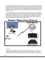
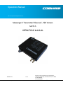
Messenger 2 Transmitter Enhanced – SDI Version
M2TE-S
OPERATIONS MANUAL
100-M0171X3
1 of 95
GMS Inc. doing business as Cobham Tactical Communications and Surveillance
Cobham Tactical Communications and Surveillance
1916 Palomar Oaks Way, Suite 100, Carlsbad, CA 92008
Tel: 760-496-0055
FAX: 760-496-0057
www.cobham.com/tcs
Table of Contents
1. Important Warning and General Safety Information .................................................................................................7
1.1 General ...........................................................................................................................................................................................................7
2. Acronyms ....................................................................................................................................................................................................9
3. Introduction ..........................................................................................................................................................................................10
3.1 About the Manual..................................................................................................................................................................................10
3.2 Warranty ....................................................................................................................................................................................................10
3.3 Safe Operating Procedures ...............................................................................................................................................................10
4. General System Information .....................................................................................................................................................11
4.1 Overview ....................................................................................................................................................................................................11
4.2 Video Quality and 2K or 4K Transmission..................................................................................................................................15
5. Hardware Overview ...........................................................................................................................................................................17
5.1 M2TE-S Connectors .............................................................................................................................................................................17
5.1.1 RF Output, Ant Port......................................................................................................................................................................17
5.1.2 ASI Out ..............................................................................................................................................................................................18
5.1.3 HD/SD-SDI IN/ASI IN/COMPOSITE .....................................................................................................................................18
5.1.4 DC IN ..................................................................................................................................................................................................18
5.1.5 I/O – CONTROL ..............................................................................................................................................................................18
5.2 Analog Audio Input Configurations..............................................................................................................................................20
6. Local Control Panel Operation ..................................................................................................................................................22
6.1 Local Control Panel Introduction ...................................................................................................................................................22
6.2 Local Control Panel Physical layout ..............................................................................................................................................22
6.3 Power-up Sequence..............................................................................................................................................................................23
6.4 Numbered LEDs ......................................................................................................................................................................................24
6.5 Key Pads .....................................................................................................................................................................................................26
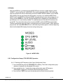
6.5.1 “MODE” Key Pad ............................................................................................................................................................................26
6.5.2 Arrow Key Pads “↑↓←→”......................................................................................................................................................26
6.5.3 Enter Key Pad “ENTR“ .................................................................................................................................................................26
6.6 Modes..........................................................................................................................................................................................................27
6.6.1 Configuration Groups (CFG GRPS LED) Operation........................................................................................................27
6.6.2 RF LEVEL (Green LED) .................................................................................................................................................................28
6.6.3 Analog AUDIO (Green LED) .....................................................................................................................................................28
6.6.4 ENCRYPTION (THE “KEY”
Green LED) ...................................................................................................................29
6.6.5 REPORT (Green LED) ....................................................................................................................................................................30
6.7 Status LEDs ...............................................................................................................................................................................................31
6.7.1 RF ON..................................................................................................................................................................................................32
6.7.2 INPUT .................................................................................................................................................................................................32
6.7.3 MIC ......................................................................................................................................................................................................32
6.7.4 4k Operation ...................................................................................................................................................................................32
6.7.5 ENCRYPTION (THE “KEY”
) .........................................................................................................................................33
100-M0171X3
GMS Inc. doing business as Cobham Tactical Communications and Surveillance
2 of 95
www.cobham.com/tcs
6.7.6 ERROR .................................................................................................................................................................................................33
6.8 Locking the local control panel interface ...................................................................................................................................33
6.8.1 Setup lock .........................................................................................................................................................................................33
6.8.2 Locked Modes ................................................................................................................................................................................33
7. Software Overview ............................................................................................................................................................................35
7.1 Product Control & Status Monitoring Approach ....................................................................................................................35
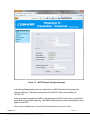
7.2 M2TE Web Interface ...........................................................................................................................................................................37
7.3 Account Management ........................................................................................................................................................................37
7.4 Internet Connection ............................................................................................................................................................................37
7.5 Group Configurations ..........................................................................................................................................................................43
7.5.1 Individual Configuration Group Setup ...............................................................................................................................43
7.5.2 Configuration Groups File Import ........................................................................................................................................56
7.5.3 Configuration Groups File Export .........................................................................................................................................57
7.5.4 Restoration of Default Groups ...............................................................................................................................................57
7.6 Status ...........................................................................................................................................................................................................58
7.7 System Setup...........................................................................................................................................................................................59
7.7.1 RF Power ...........................................................................................................................................................................................59
7.7.2 Encryption ........................................................................................................................................................................................ 60
7.7.3 Control Panel ..................................................................................................................................................................................62
7.7.4 Network .............................................................................................................................................................................................62
7.7.5 Serial Port .........................................................................................................................................................................................64
7.7.6 Logon Update .................................................................................................................................................................................65
7.8 System Upgrade ..................................................................................................................................................................................... 66
7.8.1 Firmware Upgrade ........................................................................................................................................................................67
7.8.2 Optional Features .........................................................................................................................................................................69
7.9 Help ..............................................................................................................................................................................................................71
8. Initial Checkout ..................................................................................................................................................................................72
8.1 Getting Started .......................................................................................................................................................................................72
9. Specifications .......................................................................................................................................................................................74
100-M0171X3
GMS Inc. doing business as Cobham Tactical Communications and Surveillance
3 of 95
www.cobham.com/tcs
List of Tables
Table 1 – Recommended 1.0/2.3 3G mating connector .................................................................................................................. 18
Table 2 – Recommended 1.0/2.3 3G mating connector .................................................................................................................. 18
Table 3 – Recommended DC IN mating connector ........................................................................................................................... 18
Table 4 – Recommended VHDCI mating connector with Cable .................................................................................................. 19
Table 5 – I/O - Control VHDCI-68 Connector Pin Out ...................................................................................................................... 19
Table 6 - Audio Configurations..................................................................................................................................................................... 21
Table 7 - Report Error Table ........................................................................................................................................................................... 31
List of Figures
Figure 1 – M2TE-S Connectors..................................................................................................................................................................... 17
Figure 2 - M2TE control panel ...................................................................................................................................................................... 23
Figure 3 - Numbered LEDs............................................................................................................................................................................... 24
Figure 4 - Alphanumeric Characters Displayed on Numbered LED’s .......................................................................................... 25
Figure 5 - Key Pads ............................................................................................................................................................................................. 26
Figure 6 - MODES LEDs ..................................................................................................................................................................................... 27
Figure 7 - “STATUS” LEDs ................................................................................................................................................................................ 32
Figure 8 – M2TE serial port connection configuration ..................................................................................................................... 39
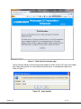
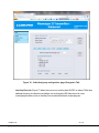
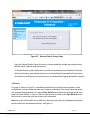
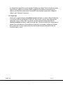
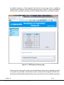
Figure 9 – Web interface welcome page ................................................................................................................................................. 41
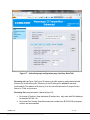
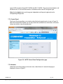
Figure 10 – Login window ............................................................................................................................................................................... 41
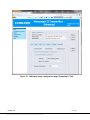
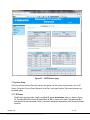
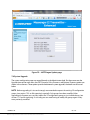
Figure 11 – Web interface main page ....................................................................................................................................................... 42
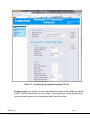
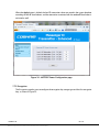
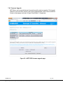
Figure 12 – Individual group configuration page (RF Tab) ............................................................................................................. 43
Figure 13 - Individual group configuration page (Video Tab) ....................................................................................................... 46
Figure 14 - Individual group configuration page (Audio Tab) ....................................................................................................... 47
Figure 15 - Individual group configuration page (TS Tab) .............................................................................................................. 49
Figure 16 - Individual group configuration page (Encryption Tab) ............................................................................................ 50
Figure 17 - Individual group configuration page (Auxiliary Data Tab) ...................................................................................... 51
Figure 18 - Individual group configuration page (Streaming-In Tab)........................................................................................ 53
Figure 19 - Individual group configuration page (Streaming-Out Tab) .................................................................................... 54
Figure 20 – Multi-group configuration file import .............................................................................................................................. 56
Figure 21 – Multi-group configuration file export through Mozilla Firefox ........................................................................... 57
Figure 22 – Restore Default Groups Page ................................................................................................................................................ 58
Figure 23 – M2TE Status page ...................................................................................................................................................................... 59
Figure 24 – M2TE RF Power Configuration page................................................................................................................................. 60
Figure 25 – M2TE Encryption Configuration page ............................................................................................................................. 61
Figure 26 – M2TE Control Panel Configuration page ........................................................................................................................ 62
Figure 27 – M2TE Network Configuration page .................................................................................................................................. 63
Figure 28 – M2TE Serial Port Configuration page ............................................................................................................................... 65
Figure 29 – M2TE Logon Update page ..................................................................................................................................................... 66
Figure 30 - M2TE DSP firmware upgrade page ..................................................................................................................................... 67
Figure 31 – M2TE Xilinx firmware upgrade page................................................................................................................................. 69
Figure 32 – M2TE optional feature page ................................................................................................................................................. 70
Figure 33 – M2TE Help page ......................................................................................................................................................................... 71
Figure 34 – Basic M2TE Link Setup............................................................................................................................................................. 72
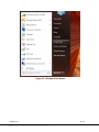
Figure 35 - Windows Start Button .............................................................................................................................................................. 80
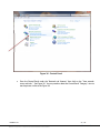
Figure 36 - Control Panel ................................................................................................................................................................................. 81
100-M0171X3
GMS Inc. doing business as Cobham Tactical Communications and Surveillance
4 of 95
www.cobham.com/tcs
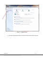
Figure 37 - Network Center ............................................................................................................................................................................ 82
Figure 38 - Network Connections ............................................................................................................................................................... 83
Figure 39 - LAN Properties .............................................................................................................................................................................. 84
Figure 40 - TCP/IPv4 Properties ................................................................................................................................................................... 85
Figure 41 - Static IP Address.......................................................................................................................................................................... 86
List of Appendices
Appendix A - IP Static Addressing and Interfacing to a Personal Computer ..............................................79
A.1. Static ..........................................................................................................................................................................................................79
A.2. DHCP (Dynamic Host Configuration Protocol) ......................................................................................................................87
Appendix B - Cable, M2T External Breakout Cables .......................................................................................................88
Appendix C - Factory Default Set-up Groups ......................................................................................................................90
100-M0171X3
GMS Inc. doing business as Cobham Tactical Communications and Surveillance
5 of 95
www.cobham.com/tcs
Revision History
Revision
Date
Main Changes from Previous version
X1
2 Sept 2011
Initial Release
X1A
12 Dec 2011
Add Appendix (A) – IP Static Addressing , Interfacing to
a Personal Computer
TG
X2
18 April 2012
Add operational description of new FW (DSP 2.0 w
Xilinx 5) release where applicable.
TG
X3
Add operational description of new FW (DSP 2.201 w
Xilinx 6). New video auto detection, frame reduction,
28 Sept 2012
new default groups, new AES-C encryption, update
figures with latest GUI pictures.
100-M0171X3
GMS Inc. doing business as Cobham Tactical Communications and Surveillance
Edited by
Checked
TGM
TG
6 of 95
www.cobham.com/tcs
1. Important Warning and General Safety Information
1.1 General
The following information is presented to the operator to ensure awareness of potential harmful RF
(radio frequency) exposure and general hazards. With regards to potential harmful RF
electromagnetic fields the text below is only a brief summary highlighting the possible risks and how
to minimize exposure. The summary is based on OET Bulletin 65 “Evaluating Compliance with FCC
Guidelines for Human Exposure to Radiofrequency Electromagnetic Fields”.1 The user should
carefully read and comprehend the following before operating the equipment and for additional in
depth information refer to OET Bulletin 65.
1. FCC has set guidelines1 for evaluating exposure to RF emissions that the user must be aware of
when operating the M2TE microwave transmitter. The maximum power density allowed from
1.7-7.0GHz is 5mW/cm2 for occupational/controlled exposure* and 1mW/cm2 for general
population/uncontrolled exposure**. These are the limits for maximum permissible exposure
(MPE) as called out in the FCC guidelines (for the above mentioned frequencies).
2. Exposure is based upon the average time spent within the RF field with a given intensity (field
units in mW/cm2)2. Hence it may be controlled (or at least minimized) by observing the safe
distances and time exposed. Safe distances are calculated from equations predicting RF Fields.3
3. The transmitter is a mobile device, is rated at 0.2W (+23dBm) RF power and is capable of harmful
radiation if safe operating practices are not observed.
*”Occupational/controlled exposure limits apply to situations in which persons are exposed as a consequence of
their employment and in which those persons who are exposed have been made fully aware of the potential for
exposure and can exercise control over their exposure. Occupational/controlled exposure limits also apply where
exposure is of a transient nature as a result of incidental passage through a location where exposure levels may
be above general population/uncontrolled limits (see below), as long as the exposed person has been made fully
aware of the potential for exposure and can exercise control over his or her exposure by leaving the area or by
some other appropriate means……..” (2)
** “General population/uncontrolled exposure limits apply to situations in which the general public may be
exposed or in which persons who are exposed as a consequence of their employment may not be made fully
aware of the potential for exposure or cannot exercise control over their exposure. Therefore, members of the
general public would always be considered under this category when exposure is not employment-related, for
example, in the case of a telecommunications tower that exposes persons in a nearby residential area.“ (2)
4. Antenna minimum safe operating distance is 20cm (8inches) when using a 2dB Omni
antenna. It is the responsibility of the qualified end-user of this intentional radiator to control the
save distances and exposure limits to bystanders.
1
OET Bulletin 65, Appendix A Table 1 Limits for MPE
http://www.fcc.gov/Bureaus/Engineering_Technology/Documents/bulletins/oet65/oet65.pdf
2
OET Bulletin 65, page 9, definitions of types of exposure
3
OET Bulletin 65, page 19, Equations for predicting RF Fields
http://www.fcc.gov/Bureaus/Engineering_Technology/Documents/bulletins/oet65/oet65.pdf
100-M0171X3
GMS Inc. doing business as Cobham Tactical Communications and Surveillance
7 of 95
www.cobham.com/tcs
5. Do not substitute any antenna for the one supplied or recommended by the
manufacturer. The installer is responsible for ensuring that the proper antenna is installed.
6. It should be noted that this device is an intentional radiator, hence:
Changes or modifications not expressly approved by the party responsible for
compliance could void the user’s authority to operate the equipment.
NOTE: The manufacturer is not responsible for any radio or TV interference caused
by unauthorized modifications to this equipment. Such modifications could void the
user’s authority to operate the equipment.
7. DC power (+12VDC nominal) to the unit should never be applied until the antenna (or other
suitable load) has been attached to the device SMA RF output connector. Safe operating
procedures must be observed when unit is transmitting into an antenna (see sections 1 &2
above).
8. Electro-Static Discharge (ESD) precautions should be observed as a safe practice.
9. The transmitter will generate considerable heat and is the responsibility of the end user to
properly heat sink the device before using.
100-M0171X3
GMS Inc. doing business as Cobham Tactical Communications and Surveillance
8 of 95
www.cobham.com/tcs
2. Acronyms
This section lists and describes the various acronyms used in this document.
Name
Meaning
16 QAM
64 QAM
A/V
AES
ASI
BDC or BDCC
COFDM
CVBS/Y
D/C
FEC
GUI
HD
I/O
Kbaud
Kbps
Mbps
MER
MPEG
MSR
M2D
M2TE
M2L
NTSC
PAL
QPSK
RF
RX
S/N
SD
SDI
TX
16-state Quadrature Amplitude Modulation
64-state Quadrature Amplitude Modulation
Audio/Video
Advanced Encryption System (32 bit)
Asynchronous Serial Interface
Block down converter
Coded Orthogonal Frequency Division Multiplexing
Composite video/Luminance with S-video
Down-Converter
Forward Error Correction
Graphical User Interface
High Definition
Input/ Output
Kilobaud per second
Kilobits per second
Megabits per second
Modulation Error Rate
Moving Picture Experts Group
Messenger Smart Receiver
Messenger Two Decoder
Messenger Two Transmitter Enhanced
Messenger Two Link
National Television System Committee
Phase Alternation Line
Quadrature Phase Shift Keying
Radio Frequency
Receiver
Signal-to-Noise Ratio
Standard Definition
Serial Digital Interface
Transmitter
100-M0171X3
GMS Inc. doing business as Cobham Tactical Communications and Surveillance
9 of 95
www.cobham.com/tcs
3. Introduction
3.1 About the Manual
Cobham User Manuals focus on providing the end user an easy to understand operational
instructions to quickly setup and deploy the equipment. The Cobham Technical Operation Manuals
focus on the technical details and setup of the equipment. The Technical Manuals also provide a
more in depth explanation of the settings and specifications of the equipment that technicians can
use to verify the operational status.
3.2 Warranty
Cobham offers a 12 month standard product warranty. During this period, should the customer
encounter a fault with the equipment we recommend the following course of action:
Check the support section of the website for information on that product and any
software/firmware upgrades.
If fault persists call our support line and report the fault. If fault persists and you are informed
to return the product, please obtain an RMA number from the Cobham support department
or website and ship the equipment with the RMA number displayed and a description of the
fault. Please email the support section the airway bill/consignment number for tracking
purposes.
Depending on the nature of the fault, Cobham endeavor to repair the equipment and return it to the
customer within 14 days of the item arriving at our workshops. Obviously it is impossible to cater for
all types of faults and to manage 100% replacement part availability, and delays are sometimes
inevitable.
Please contact Cobham for details of packages that can be tailored to meet your individual needs,
whether they are service availability, technical training, local geographic support or dedicated spares
holdings.
3.3 Safe Operating Procedures
Ensure that the power supply arrangements are adequate to meet the requirements of this
product.
Operate within the environmental limits specified for the product.
This product requires external cooling to stay within its operating limits. Be sure to use an
adequate heat sink.
Only authorized, trained personnel should open the product. There are no functions that
required the User to gain access to the interior of the product.
Warning: Opening this product will void its warranty!
100-M0171X3
GMS Inc. doing business as Cobham Tactical Communications and Surveillance
10 of 95
www.cobham.com/tcs
4. General System Information
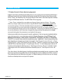
4.1 Overview
The Messenger 2 Transmitter Enhanced (M2TE) is a second generation AVC HD/SD COFDM transmitter
that combines all the features and capabilities of Cobham Surveillance’s (CS’s) Messenger 2 AVC HD/SD
Transmitter with the additional features listed in the Key System Features section below. All of this is
included in a smaller housing (8.6 cu inches). Key features include optional Dual Audio/Video/Data
processing with end to end system-level latencies of down to ~44 mS when used with CS
Receiver/Decoders.
The Ultra-low system latency greatly enhances real-time operating when the link is used in time critical
situations like piloting Unmanned Aerial Vehicles (UAVs) or Unmanned Ground Vehicles (UGVs) or in
threat response. Optional Dual video processing enables 3D content collection which provides depth
perception and greater control for UGV applications requiring fine spatial operations like explosive device
de-arming. The M2TE’s 3D capability also enhances Entertainment, Sports, and ENG applications.
The M2TE can optionally provide time-correlated KLV-1 and KLV-2 META data processing4 that is used in
Airborne Surveillance Applications and Geospatial determination. The META data can be extracted from
the SDI/HD-SDI video’s ancillary data space or input on a separate RS-422 interface.
The M2 Series “Messenger Two Series” product line incorporated AVC / H.264 compression technology
with ultra-low delay that covers all the SD and HD formats up to 1080P. AVC compression provides
dramatically increased compression efficiency over MPEG-2 which allows our link to provide superior
coverage over a wider operating range!
There are two core hardware configurations for M2TE. The HD/SD-SDI configuration accepts up to two
Standard Definition (SD) or High Definition (HD) 4:2:2 Digital Video (HD/SD- SDI) or analog composite
Video and Analog Stereo Audio Inputs (Mic or Line Level) and/or optional Embedded Audio up to a total
of two stereo pairs or four mono channels sets or one stereo pair or two mono channels per program.
Mic bias is also provided. In the HDMI configuration4, the HD/SD-SDI interfaces are replaced with two
HDMI interfaces that accept both digital video and audio.
Both Video programs can be compressed according to the Advanced Video Compression (AVC) / H.264
(HD/SD) specification with the same or different frame resolutions, rates and formats. The low-latency
AVC Encoder supports the Baseline Profile with extensions with resolutions from 480 to 1080 with
support for either interlaced or progressive formats. The Audio is compressed using MPEG-1 Layer 2
compression. Low rate Auxiliary data up to 115 KBaud can be optionally supported. Both programs
Audio, Video and Auxiliary Data Packets PES Streams are multiplexed with Basic Service Data to indicate
their respective Service Names. If two programs are active, the two transport streams are multiplexed
into a single multi-program stream. The stream can be optionally scrambled with AES scrambling system
to provide protection in sensitive applications. User selections for all transport stream ID numbers and
service names are provided.
The M2TE is a complete system with Audio/Video encoders/compressors and all the required processing
to transmit the modulated signal with up to 200mW of RF over a wide variety of RF bands. External
Power Amplifiers are available to boost the signal to up to 15W (band dependent). CS’ COFDM wireless
4
In development, future update
100-M0171X3
GMS Inc. doing business as Cobham Tactical Communications and Surveillance
11 of 95
www.cobham.com/tcs
equipment provides standard a robust digital modulation system known as Coded Orthogonal Frequency
Division Multiplexed (COFDM) that provides frequency diversity and powerful Forward Error Correction
(FEC) algorithms. This modulation is ideas for transmitting over water or into urban environments which
typically have high multi-path interference. Product development plans include the ability to switch via a
command to single carrier modulations for Line of Sight (LOS) applications and compatibility with other
surveillance systems.
Our Messenger Receivers include an option for Spatial Maximal Ratio Pre-Detect Diversity Combining to
combat multipath reflections found in indoor/urban environments. CS’ Messenger six or eight channel
receivers with associated Messenger Antenna Arrays (MAAs) provide wide reception range without the
hassle and cost of an auto tracking antenna system. The Messenger series Tx/Rx products provide a
robust wireless link that is effective against the multipath interference experienced by analog systems
and provides reliable data transmission in the most difficult of terrains.
LAN/IP Port
The M2TE contain a 10/100BaseT LAN interface that can be used both for Control & Status monitoring
and for Transport Stream (TS) streaming in and out of the device. The IP address can be assigned
automatically via a DHCP server or via manual settings. Control & Status monitoring is accomplished via
100-M0171X3
GMS Inc. doing business as Cobham Tactical Communications and Surveillance
12 of 95
www.cobham.com/tcs
a WEB server application that launches from the device. TSs can be sent out or in via UDP/IP or
RTP/UDP/IP protocols.
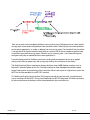
3D Support
3D is a very new area in the Broadcast industry. From a content collection standpoint it is normally
accomplished with two separate cameras that are GEN-LOCKED together outputting two separate Video
signals.
Content Collection Format
The encoder maintains a frame by frame synchronization as it goes through its processing.
AES Scrambling
The AES Scrambling option can be used to add security to your data transmission. The system scrambles
the payload portion of the TS packets. Only the TS header remains unscrambled to enable operation with
standard DVB-T receivers. The 256/128 bit-scrambling key is entered through the M2TE’s control
interface. The user can enable or disable the scrambling as well as choosing if the key is stored within the
Tx or not via CS’ Microsoft Windows control program. Encryption on/off is also available from the local
control panel (if it was previously turned ON).
Local Control Panel
The M2TE includes a simple local control panel that allows the selection of up to 20 set-up
configurations, Encryption Enable/Disable, switch between Mic and Line Level inputs and selection of 4
output power levels. Status indicators are provided for the presence of input Audio, Video and RF
output. Each of these set-up configurations can independently control every programmable parameter in
the TX including RF Frequency, Modulation Mode, Compression Modes and Video Resolution to name a
few. These Set-Up Groups can be configured by Administrative Personnel using the CS M.S. Window’s
Control Application prior to fielding the equipment.
This manual provides information on how to operate the M2T-E as well as pertinent technical
information related to the overall system. Refer to the model identifier (on-line document, 100MNI0115 - latest revision) at the Cobham website, http://www.cobham.com/tcs, for available frequency
and power configurations along with options.
100-M0171X3
GMS Inc. doing business as Cobham Tactical Communications and Surveillance
13 of 95
www.cobham.com/tcs
Key System Features
Ultra-Low End to End System Latency (down to ~44 mS)5
AVC HD/SD Encoder (Up to 1080p 30FPS)
Supports Dual Audio/Video/Data programs (Option)
o Multi-Camera Support
o 3D Support
COFDM Modulation (DVB-T 2 K or 4 K Carriers6)
Bandwidths DVB-T 6,7,& 8 MHz (STD) & 12, 14 & 16 MHz (4 K6)
Output Frequency: 0.9 to 7 GHz (In-Bands)
Dual L/S Band Capability
Dual 3Gbps HD/SDI-SDI and Analog SD Video Input Interfaces Option
Dual HDMI Video Input Interfaces Option7
Analog Audio and Embedded Audio
Transport Stream Streaming via LAN or ASI or Serial Interface
Time Correlated KLV Meta Data handling7
Secure – BCRYPT AES 128/256 Encryption or AES-C 128/256
Control via local panel or remote LAN Web Server or Serial Interface
Video Input(s) format type automatically detected-no setup required by user
Signal Processing
The Messenger 2 Transmitter Enhanced (M2TE) series accepts up to two Standard Definition (SD) or
High Definition (HD) 4:2:2 digital videos or analog SD videos and analog stereo audio inputs (Mic or
Line level). Each video is compressed independently according to the Advanced Video Compression
(AVC) /h.264 specifications. Therefore, the video inputs can either the same resolution and frame
rate or completely different resolutions and frame rates. The low-latency AVC Encoder supports the
Baseline Profiles with resolutions from 480 to 1080 with support for either interlaced or progressive
formats. The audio is compressed using MPEG layer II compression. Low rate Auxiliary data up to
115 KBaud can be optionally supported.
The basic system supplies support for generation of a single audio/video/data program within a
MPEG Transport Steam (TS). The audio, video and auxiliary data packets PES streams are multiplexed
with basic service data to indicate the service name. The stream can be scrambled with AES
scrambling system to provide protection in sensitive applications.
The dual system option supplies support for generation of two independent audio/video/data
programs within a single MPEG Transport Steam (TS). The dual program stream can also be
scrambled with AES scrambling system to provide protection in sensitive applications.
The M2TE can operate in one of two modes When the Transmit Mode is enabled the TS will be sent
to the COFDM RF transmission processing section. In this mode it can also be streamed out
optionally the ASI output port and/or the LAN port for local distribution or recording on external
5
When used in Ultra-Low Latency mode (Intra-Refresh) with Cobham’s Messenger 2 Decoders and Receiver Decoders
With 4K High-Throughput Option on M2TE or Encoder Mode
7
In development, future update
6
100-M0171X3
GMS Inc. doing business as Cobham Tactical Communications and Surveillance
14 of 95
www.cobham.com/tcs
devices. The second operating mode is the Encoder-Only Mode. In this mode the COFDM RF
transmission chain is disabled and only the ASI and LAN ports are active.
There are two COFDM operating modes available; standard 2K DVB-T compliant and a Cobham
unique 4K mode8. The 4K mode provided twice the data throughput than 2K mode (2x RF
bandwidth) and allows the transmission of high quality dual HD video in a robust 16-QAM format.
COFDM 2K Carrier Mode
In 2K Mode the M2TE uses standard DVB-T coding and modulation. DVB-T stands for Digital Video
Broadcasting — Terrestrial; it is the DVB European-based consortium standard for the broadcast
transmission of digital terrestrial television that was first broadcast in the UK in 1997. This system
transmits compressed digital audio, video and other data in an MPEG transport stream, using coded
orthogonal frequency-division multiplexing (COFDM or OFDM) modulation.
The OFDM scheme works by splitting the digital data stream into a large number of slower digital
streams each of which digitally modulate a set of closely spaced adjacent carrier frequencies. COFDM
goes a step further by using a “Coding” scheme to map the data onto the multiple carriers in a way
that maximizes recovery from link errors. This coding includes Forward Error Correction with
Convolution Interleaves’ and Reed Solomon encoding along with careful distribution of the data onto
the multiple carriers. COBHAM CS has chosen to use 2K carrier in which 1,705 carriers actually carry
the payload that are approximately 4KHz apart. DVB-T offers three different modulation schemes
(QPSK, 16QAM, 64QAM).
4K Carrier Mode
The 4K HIGH-THROUGHPUT OPTION enables user-selectable options to set bandwidths from 6 MHz
to 16 MHz and to double the throughput of our standard M2T (Up to 63 Mbps!). In 2K carrier mode
the system would need to operate in 64-QAM to support dual program/video operations. Using 4K
carriers and the 16 MHz bandwidth, the link can support dual program/video HD operation using 16
QAM. This increases link robustness and provides an additional 13.5 dB of gain with a link margin
increase greater than 4.7 x in operating range! For the same throughput rate in a standard HD MPEG2 DVB-T system! With the 4 K HIGH-THROUGHPUT OPTION you can run with fully DVB-T compliant
2K carriers and bandwidths of 6, 7, or 8 MHz. When you switch to 4K carriers you can select 12, 14
or 16 MHz bandwidth.
4.2 Video Quality and 2K or 4K Transmission
The M2TE uses Advanced Coding Standard (AVC) also known as h.264 or MPEG-4 Part 10. It is 3040% more compression efficient than MPEG-2 which helps achieve high quality HD or SD video
through a standard 2K DVB-T wireless link.
Video quality depends on many complex factors including;
8
Video resolution and frame rate
Single or dual video processing
With 4K High-Throughput Option on M2TE or Encoder Mode
100-M0171X3
GMS Inc. doing business as Cobham Tactical Communications and Surveillance
15 of 95
www.cobham.com/tcs
Level of detail and contrast
Level of motion in the video
Level of noise in the video
Existence of repeating patterns in the video
The required level of video quality will not be the same for all applications. Broadcasters often
demand high-quality while certain surveillance applications may be satisfied with much less quality.
Since we support a wide variety of applications we allow a wide range of settings. Not every set-up
configuration will be acceptable for all applications.
Through experimentation it has been found that a single 1080 resolution HD video at 30 fps can be
supported with very good video quality under most video conditions at ~16 Mbps. 720p @60 fps
needs ~14 Mbps for similar quality. Simple HD video scenes can be supported at very low bit rates,
4Mbps for example. However, they will degrade rapidly with motion or noise. The M2TE’s factory
defaults for single program/video operation are set to the aforementioned levels which can be
accomplished with 2K DVB-T transmission using 16-QAM which is reasonably robust in most wireless
environments.
The factory defaults for dual program (dual video) with 2K DVB-T run in 64-QAM operation and
allocate ~12 Mbps per program/video. At these rates the video will still be good. However, as the
videos become more demanding there will be more artifacts. Also, 64-QAM operation will reduce the
operating range and robustness of the link.
If you are using a mixture of HD and SD you can allocate more of the data bandwidth to the HD
program using the Video Bit Rate Allocation controls in the set-up configuration group parameter.
This parameter allows the user to allocate a percentage of the channel bit rate to program A vs. B.
If you want to get the video quality and range of our single program/video operation with dual HD
videos you will need to go to our 4K operation which doubles the throughput of the link. Note that
the RF bandwidth is also doubled. However, in this mode you will be able to go back to 16-QAM and
have high video quality with reasonable link range and robustness.
100-M0171X3
GMS Inc. doing business as Cobham Tactical Communications and Surveillance
16 of 95
www.cobham.com/tcs
5. Hardware Overview
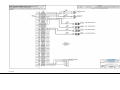
The basic M2TE-S transmitter configuration is outlined in this section:
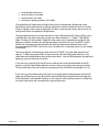
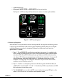
Figure 1 – M2TE-S Connectors
5.1 M2TE-S Connectors
There are six connectors located on the M2TE-S unit as shown in Figure 1. They are for interfacing
the RF out, HD//SD-SDI Video or ASI in or SD Composite in (Two ports), ASI out, audio, Auxiliary
Data, KLV Data, LAN/IP and Control signals. The Local Control panel is also shown in Figure 1.
5.1.1 RF Output, Ant Port
The M2TE uses a female SMA connector for its ‘RF Output’ port. The antenna is normally
attached here. This port can also drive additional external amplifiers for high-power applications
like Aerial downlinks.
Note: Transmitters should not be powered on without a load attached to the RF
output. Doing so could damage the internal Power Amplifier (PA).
100-M0171X3
GMS Inc. doing business as Cobham Tactical Communications and Surveillance
17 of 95
www.cobham.com/tcs
5.1.2 ASI Out
A 75 Ohm female 1.0/2.3 3Gbps connector is provided for DVB-ASI Transport Stream Output.
The output bit rate is 270 Mbps.
Table 1 – Recommended 1.0/2.3 3G mating connector
Manufacturer
Part Number
Cambridge
XGT-8000-NGAF
5.1.3 HD/SD-SDI IN/ASI IN/COMPOSITE
Both video input ports use a 75 Ohm female 1.0/2.3 3Gbps connector for SD-SDI or HD-SDI or
SD composite video input streams. The input bit rate is 270 Mbps for SD and 1.485 Gbps to 2.97
Gbps for HD. The Composite SD inputs can support either NTSC or PAL video formats.
In addition these input connectors can be used as an input for ASI DVB compliant Transport
Streams. See section 7, software overview, for details on the Input Modes. This section explains
how to switch from SDI IN to ASI IN using the Cobham M2TE Web Configurator.
Table 2 – Recommended 1.0/2.3 3G mating connector
Manufacturer
Part Number
Cambridge
XGT-8000-NGAF
5.1.4 DC IN
The M2TE accepts +9-+32V DC on a 4 position LEMO connector. Pins 1 & 2 connect to +VDC
and Pins 3 & 4 connect to GND.
Table 3 – Recommended DC IN mating connector
Manufacturer
LEMO
ODU
Part Number
FGG.0B.304.NLAS2
S10LON-P04MFG0-5200
5.1.5 I/O – CONTROL
The ‘I/O - CONTROL’ connector is a male, high-density VHDCI-68. It is used to provide the
interface for audio, Mic Bias, Auxiliary data, KLV data, RS-232, LAN/IP control & streaming, I/O
interface.
Normally, the M2TE is controlled via the LAN/IP interface via an internally launched WEB
interface. However, it also has two separate RS232 channels/interfaces that can be used one at
a time for control and monitoring the unit. These same interfaces can be used to send
asynchronous low-Rate DATA along with the audio and video.
100-M0171X3
GMS Inc. doing business as Cobham Tactical Communications and Surveillance
18 of 95
www.cobham.com/tcs
Table 4 – Recommended VHDCI mating connector with Cable
Manufacturer
Part Number
MOLEX
79918-0080
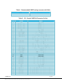
Table 5 – I/O - Control VHDCI-68 Connector Pin Out
Pin
Signal
Notes
1
35
2
36
3
37
4
38
5
39
6
40
7
41
8
42
9
43
10
44
11
45
12
46
13
47
14
48
15
49
16
50
17
51
18
52
19
53
20
GND
GND
RS232 Data RX1
RS232 Data TX1
RS232 Data RX2
RS232 Data TX2
GND
GND
AUDIO 1 DIFF P
AUDIO 1 DIFF N
AUDIO 1 BIAS
AUDIO 2 BIAS
Digital GND
Digital GND
RS232 Port 1
RS232 Port 1
RS232 Port 2
RS232 Port 2
Digital GND
Digital GND
Positive AUDIO input 1
Negative AUDIO input 1
Microphone 1 Bias Voltage (+1.5 volts)
Microphone 2 Bias Voltage (+1.5 volts)
Factory only use – leave this pin open
Factory only use – leave this pin open
GND for Audio Signals
GND for Audio Signals
Factory only use – leave this pin open
Factory only use – leave this pin open
Microphone 3 Bias Voltage (+1.5 volts)
Microphone 4 Bias Voltage (+1.5 volts)
Positive AUDIO input 2
Negative AUDIO input 2
GND for Audio Signals
GND for Audio Signals
Digital GND
Digital GND
Reserved for special applications
Reserved for special applications
Reserved for special applications
Reserved for special applications
Reserved for special applications
Reserved for special applications
Digital GND
Digital GND
Port A – For KLV Meta data and other serial data
Port A – For KLV Meta data and other serial data
Port B – For KLV Meta data and other serial data
Port B – For KLV Meta data and other serial data
Port C – For KLV Meta data and other serial data
AUDIO GND
AUDIO GND
AUDIO 3 BIAS
AUDIO 4 BIAS
AUDIO 2 DIFF P
AUDIO 2 DIFF N
AUDIO GND
AUDIO GND
GND
GND
IO BRD ID0
IO BRD ID1
DSP GPIO1
DSP GPIO0
DSP GPIO2
DSP GPIO3
GND
GND
RS422-A P
RS422-A N
RS422-B P
RS422-B N
RS422-C P
100-M0171X3
GMS Inc. doing business as Cobham Tactical Communications and Surveillance
19 of 95
www.cobham.com/tcs
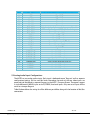
Pin
Signal
Notes
54
21
55
22
56
23
57
24
58
25
59
26
60
27
61
28
62
29
63
30
64
31
65
32
66
33
67
34
68
RS422-C N
GND
GND
3.3v I/O
3.3v I/O
3.3v I/O
3.3v I/O
FPGA GPIO3
FPGA GPIO2
FPGA GPIO1
FPGA GPIO0
USB D P
USB D N
USB VBUS
PA EN
SPARE 0
SPARE 1
GND
+3.3V
ENET LTC LED
ENET LTA LED
ENET RTC LED
ENET RTA LED
CHASSIS GND
CHASSIS GND
ENET RD P
ENET RD N
ENET TD P
ENET TD N
Port C – For KLV Meta data and other serial data
Digital GND
Digital GND
Reserved
Reserved
Reserved
Reserved
Video1 and video 2 reference clock test point. Selectable
GPS one Pulse Per Second (1PPS), 3.3v standard input.
Reserved for special applications
Reserved for special applications
Part of USB interface
Part of USB interface
Part of USB interface
External PA Control (+3V TTL ON)
Reserved for special applications
Reserved for special applications
Digital GND
Part of LAN I/P interface
Part of LAN I/P interface
Part of LAN I/P interface
Part of LAN I/P interface
Safety Ground connected to housing
Safety Ground connected to housing
Part of LAN I/P interface
Part of LAN I/P interface
Part of LAN I/P interface
Part of LAN I/P interface
5.2 Analog Audio Input Configurations
The M2TE has two analog audio circuits. Each circuit is dedicated to one “Program” and has separate
configurations/settings for Line and Mic levels. Remember that each of the two video inputs are
processed and distributed as separate Programs in the M2TE’s Transport Stream. These ports support
a single differential (MONO) input or dual (STEREO) Line-Level inputs. Only one set of inputs will be
active at a time per Program.
Table 6 below defines the wiring for all the different possibilities along with the location of Mic Bias
connections.
100-M0171X3
GMS Inc. doing business as Cobham Tactical Communications and Surveillance
20 of 95
www.cobham.com/tcs
Table 6 - Audio Configurations
Audio Configuration
Program #1 Audio
Program #2 Audio
(reference table 5 above)
(reference table 5 above)
Pin 5 ( + input)
Pin 11 ( + input)
Pin 39 (- input)
Pin 39 (- input)
Pin 42 (AUDIO GND)
Pin 46 (AUDIO GND)
Single ended high input
impedance (100K)
Line 1: Pin 5, AUD GND Pin 8
Line 3: Pin 11, AUD GND Pin 12
Mic Bias (1.5 VDC)
#1 Pin 6
#3 Pin 10
#2 Pin 40
#4 Pin 44
Balanced high input
impedance (100K)
Line 2: Pin 39, AUD GND Pin 42 Line 4: Pin 39, AUD GND Pin 46
Note: If 600 Ohm input impedance is required add a parallel 600 Ohm resistor to the external cable
assembly.
100-M0171X3
GMS Inc. doing business as Cobham Tactical Communications and Surveillance
21 of 95
www.cobham.com/tcs
6. Local Control Panel Operation
Note:
The active settings are maintained in a separate non-volatile memory area; separate from the 20
Configuration Groups we call Group 0. This was done to enable the M2TE’s ability to power-up in the same
configuration that was in-play prior to the shut-down of the unit, when the Group 0 settings have NOT been
saved into 1 of the 20 Configuration Groups. Changes can be made either from the Front-Panel or from the
LAN GUI (via a LOAD command) that will only affect Group 0.
WARNING: Before attempting to make any group changes (or switching to a different group) to the
transmitter from the front Local Control Panel ensure the unit has correct video input(s) per the current
configuration attached, the unit is fully initialized and there are no video errors indicated by the Status
Error LED indicator on the front panel.
In addition any changes implemented from the front panel once the ENTR key has been pushed are
saved into the current active group (see discussion on Groups in section 7).
6.1 Local Control Panel Introduction
The M2TE can be controlled locally by a user interface panel integral to the transmitter. This
interface shows some status and control settings of the transmitter and allows some limited changes
to its operation. M2TE has preset configuration groups where you can program various common
settings from a computer then simply change the groups as desired.
There are three operational modes; Status, Configuration and Locked modes. Default Operating
Mode (Status Mode) is the main mode that the local control panel is in when not being actively used.
The Configuration Mode is when the user is using the control panel to view current settings (and
values) or is using it to change various settings. The administrator has the ability to control access to
the various modes of the local control panel, so they cannot be changed by the end user. In Locked
mode, the user has access to additional information than in the Default Operating Mode but is not
allowed to modify this information.
This section of the manual describes the control panel’s operating modes, how to read and change its
settings.
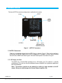
6.2 Local Control Panel Physical layout
The control panel has 4 main sections:
5 “MODES” LEDs,
6 “STATUS” LEDs,
100-M0171X3
GMS Inc. doing business as Cobham Tactical Communications and Surveillance
22 of 95
www.cobham.com/tcs
20 Numbered LEDs,
6 key pads (MODE, ENTR, 4 ARROW KEYS) for the user interface.
See Figure 2 - M2TE control panel. Each of the main sections is further explained below.
Figure 2 - M2TE control panel
6.3 Power-up Sequence
When the M2TE is first powered on, the local control panel LED is displayed in the following manner.
It will give you an indication that all systems are up and operating normally. Each new set of lights
indicate a different system check is completed. Full power up initialization should only take
approximately 15 seconds.
1) Step 1 – The red ERROR LED starts blinking immediately when power is first applied to the
M2TE. It keeps on blinking during the first part of the initialization process and then follows
the column LEDs ON and OFF initialization (see step 2 below) until full initialization of the
unit. It turns OFF if all systems are good to go (and doesn’t find any faults). If it remains ON
after full power up (after step 3 below) then this is an indication to the user of a fault
condition. The Status page in the LAN GUI is the easiest ways to find out what the fault
condition may be. Reference section 7.6
2) Step 2 -- A column at a time lights up then turns OFF. Starting with all “STATUS” LEDs, all
“MODE” LEDs, Numbered LEDs 1-5, 6-10, 11-15 and finally 16-20. Lastly all columns of LEDS
light at the same time and then go out.
3) The CFG GRPS LED turns on and the M2TE’s current configuration group LED lights up. Any
other STATUS LED turns on as it would in normal operation mode.
100-M0171X3
GMS Inc. doing business as Cobham Tactical Communications and Surveillance
23 of 95
www.cobham.com/tcs
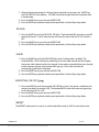
6.4 Numbered LEDs
The Numbered LED section, pictured in Figure 3 - Numbered LEDs, is used to display various
information associated for each MODE LED. Figure 4 - Alphanumeric Characters Displayed on
Numbered LED’s shows Alphanumerical and characters that are displayed. The default setting for the
numbered LEDs is the active configuration group. All Numbered LEDs are green.
Figure 3 - Numbered LEDs
100-M0171X3
GMS Inc. doing business as Cobham Tactical Communications and Surveillance
24 of 95
www.cobham.com/tcs
Figure 4 - Alphanumeric Characters Displayed on Numbered LED’s
100-M0171X3
GMS Inc. doing business as Cobham Tactical Communications and Surveillance
25 of 95
www.cobham.com/tcs
6.5 Key Pads
The 6 push button key pads, “MODE”, up”↑”, down“↓”, left”←”, right “→” and Enter “ENTR“, help the
operator change the settings and view the status of the M2TE transmission.
Figure 5 - Key Pads
6.5.1 “MODE” Key Pad
Each push of the MODE key cycles from the current mode sequentially to the next mode and in
doing so displays in the Numbered LEDs section the current settings/values for the current mode.
Pressing the MODE key after the REPORT LED is selected puts the control panel into Default
Operating Mode (Status Mode).
6.5.2 Arrow Key Pads “↑↓←→”
The arrow key pads are used to move around in the Numbered LEDs section to be able to select new
settings/values for each of the MODEs when that particular MODE has been selected, indicated by
the blinking MODE LED.
NOTE: Go to Modes section for a better description of their uses.
6.5.3 Enter Key Pad “ENTR“
Pressing the ENTR key pad implements and saves any settings/value changes. If the ENTR key is not
pressed then changes do not take place and the M2TE continues to operate without any disruptions.
100-M0171X3
GMS Inc. doing business as Cobham Tactical Communications and Surveillance
26 of 95
www.cobham.com/tcs
6.6 Modes
When the MODE key is pushed one of the MODES LED lights and starts to blink indicating which
“MODES” is active, see Figure 6 - MODES LEDs. This means the Numbered LEDs (1-20) to the right
now only represent the current value/setting of the active MODE. While the MODE is active (MODE
LED is blinking) the user can change the values/settings assuming it is a read/write MODE. Some
MODES such as the REPORT are read only MODES. As stated previously new settings/values are not
change until the ENTR key is pressed. Also some MODES may be skipped over as the MODE key is
pressed because it is not currently available. This could be because in the LAN GUI the feature was
turned OFF. For more information on how to set each MODE, see that MODES description below.
The local control panel times out if there is no keypad activity for several seconds. Unless otherwise
programmed, the mode CFG GRPs LED turns solid, indicating the front panel is in Default Operating
Mode; the Numbered LEDs display the current configuration group.
Figure 6 - MODES LEDs
6.6.1 Configuration Groups (CFG GRPS LED) Operation
6.6.1.1 Checking the RF Frequency of the Current Configuration Group
1) Press the MODE key until the “CFG GRPS” LED is blinking. The current configuration group
selection is displayed in the Numbered LEDs section.
2) Press no other keys for 1 second; the current configuration group’s RF frequency
(XXXX.XXMHz) scrolls across the Number LEDS one character at a time.
3) Press the Enter “ENTR” key to put the control panel into Default Operating Mode.
100-M0171X3
GMS Inc. doing business as Cobham Tactical Communications and Surveillance
27 of 95
www.cobham.com/tcs
NOTE: New settings/values are never changed until the ENTR key is pressed. If the current
setting is re-selected, if the panel times out, or if the Mode key is pressed then the M2TE keeps
the previous setting/value without any disturbance to the M2TE operation.
6.6.1.2 Changing Configuration Groups
1) Press the MODE key until the CFG GRPS LED is blinking. The current configuration group
selection is displayed in the Numbered LED section.
2) Use the up, down, left, and right keys, “↑↓←→” to highlight a new value (a new configuration
group 1-20). If no key is pushed for 1 second, the current highlighted selection will have its
RF frequency scroll across the Numbered LEDS in the following manner, XXXX.XXMHz.
3) To view another configuration group’s RF frequency press the arrow keys at any time,
highlight the desired configuration group LED then wait 1 second for the frequency to
display.
4) Press the ENTR key to make the current highlighted preset configuration groups active. This
sets the M2TE to the new value and puts the control panel into Default Operating Mode.
6.6.2 RF LEVEL (Green LED)
1) Press the MODE key until the RF LEVEL LED is blinking. The current RF power setting (1 to 4) is
displayed in the Numbered LED section.
2) Use the up and right keys, “↑→”, to increase the value. Use the down and left keys, “↓←”, to
decrease the value. A zero (0) value indicates RF is OFF. RF values and the corresponding
numerical indicators (1, 2, 3 or 4) are set using the LAN GUI.
3) Press the ENTR key to enable the current power level selection.
6.6.3 Analog AUDIO (Green LED)
NOTE: If the Audio MODE LED is skipped then analog audio has either been disabled or it’s been
configured for embedded audio. If audio is needed then change the configuration group to one that has
analog audio enabled. Embedded audio cannot be addressed from the front control panel, only through
the LAN GUI WEB interface.
1) Press the MODE key until the AUDIO LED is blinking. Two LEDs in the Numbered LEDS section
light for a brief time, either 1&2 or 3&4 indicating the current active audio channel; the volume
level value associated with the active audio channel is displayed next in the Numbered LEDs
section.
2) Use the up and down keys, “↑↓”, to increase/decrease the audio volume. Zero (0) value indicates
volume is at lowest power and nine (9) is at maximum.
3) Press the ENTR key to accept the new value.
100-M0171X3
GMS Inc. doing business as Cobham Tactical Communications and Surveillance
28 of 95
www.cobham.com/tcs
Note: If only one audio channel is active and the other is OFF then only the volume
adjustment for the active channel can be made. If both audio channels are active then
continue with step 4 below to switch to the other audio channel.
4) Use the left and right keys, “→ ←”, to change between the different active audio channels which
are displayed in the Numbered LEDs section ( 1&2, or 3&4), depending upon the group
configuration).
5) Use the up and down keys, “↑↓”, to increase/decrease the audio volume. Zero (0) value indicates
volume is at lowest power and nine (9) is at maximum.
6) Press the ENTR key to accept the new value.
NOTE:
Settings will not change until the ENTR key is pressed. If the current setting is reselected, if the panel times out, or if the mode key is pressed then the M2TE will keep to the old
setting without any disturbance to the M2TE operation.
6.6.4 ENCRYPTION (THE “KEY”
Green LED)
NOTE: There are a few guidelines associated with encryption which the user needs to be
aware of to have a better understanding of how the encryption MODE “
“LED works:
A. Encryption is a purchased option. If it hasn’t been purchased then in the LAN GUI under the
“Encrypt” tab in the Configuration Groups/ Setup menu the encryption mode & key buttons
are grayed out. If this is the case then the encryption MODE ”
“ key LED is skipped
over when pressing the “MODE” button.
B. Encryption must be set to either “AES/128” or “AES/256”(this is a generic term, AES
encryption modes will vary depending on which AES options have been purchased; the
modes are listed under the “Encrypt” tab in the Configuration Groups/Setup menu) using
the LAN GUI interface. Once the AES ENCRYPTION MODE has been activated from the LAN
GUI the STATUS encryption “
” key (yellow LED) on the front panel lights. The
encryption keys (up to 5 keys) should also be pre-set using the LAN GUI.
C. If the encryption MODE key “
” LED lights the user is then able to change to a predefined key, up to 5 different keys using the control panel arrow keys (↑↓→ ←). In addition
the user is also able to turn the current AES mode to OFF by selecting the zero (0) value using
the control panel arrow keys (↑↓→ ←). Or if the current mode is OFF the user can turn it back
ON by selecting one of the 5 pre-defined keys. Keep in mind the functions described here in
step C depend on step B above to be true.
With an understanding A, B & C above the following is the basic operation of the Encryption MODE
using the front control panel:
1) Press the MODE key until the KEY “
” LED is blinking. The value which appears in the
Numbered LEDs section indicates the current encryption key or if a zero (0) value the current
encryption mode is OFF (in which case the STATUS LED “
” is also OFF).
2) Use the arrow keys, “→ ←↑↓” to select a different encryption key (1 through 5). The STATUS LED
next to the key”
” turns ON if a value other than zero (0) is selected. If zero (0) value is
selected then the STATUS LED turns OFF.
100-M0171X3
GMS Inc. doing business as Cobham Tactical Communications and Surveillance
29 of 95
www.cobham.com/tcs
3) Press the ENTR key to make the current selection active. This sets the M2TE to the new settings
and puts the control panel into Default Operating Mode.
NOTE: Settings will not change until the ENTR key is pressed. If the current setting is reselected, if the panel times out, or if the MODE key is pressed then the M2TE keeps the previous
settings without any disturbance to the M2TE operation.
6.6.5 REPORT (Green LED)
NOTE: The REPORT MODE is a read only dual function mode, it displays the errors indicated
by the red “ERROR” led and can also display the current active IP address.
1) Press the MODE key until the REPORT LED is blinking.
2) If any errors are present (the red STATUS ERROR LED should be ON also) the numerical values are
displayed in the Numbered LEDs section. Reference Table 7 below for the interpretation of the
values. There can be several values displayed at one time. For example if video 1 and video 2
inputs are disconnected from the M2TE the number 1 & 2 LED would light up (in the Numbered
LEDs section) when the REPORT LED MODE is active (blinking). And if you read in table 7 below
the error for #1 is “Video 1 Input missing or invalid” and error for #2 is “Video 2 Input missing or
invalid”.
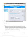
LED #
1
2
3
4
5
6
7
ERROR
Video 1 Input missing or invalid
Video 2 Input missing or invalid
Video 1 format does not match configuration
Video 2 format does not match configuration
Audio Stream 1 missing or invalid
Audio Stream 2 missing or invalid
Future Use
100-M0171X3
GMS Inc. doing business as Cobham Tactical Communications and Surveillance
30 of 95
www.cobham.com/tcs
LED #
8
9
10
11
12
13
14
15
16
17
18
19
20
ERROR
Future Use
Future Use
Future Use
Future Use
Future Use
Future Use
Future Use
Future Use
Invalid RF Board Type or missing RF card
RF Board Database is corrupted or has not been programmed
Main Database is corrupted or has not been programmed
Hardware Error
System Error
Table 7 - Report Error Table
6.6.5.1 REPORT IP Address
The following procedure can be used to read the current IP address off of the local control panel.
Press the MODE key until the REPORT LED is blinking.
Press the ENTR key.
The IP address is presented one character at a time in the Numbered LED section. Keep in mind if
DHCP addressing mode is used the M2TE IP (Ethernet) cable must be plugged into a network before
the IP address is displayed otherwise it will show all zeros, 0.0.0.0.
Note: The default factory setting is a static IP address of 192.168.1.36. If the IP addressing of
the M2TE transmitter is changed to DHCP ensure the network in which it gets attached to
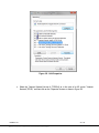
supports DHCP addressing. See Appendix A -for additional details on IP addressing and
interfacing a personal PC to the M2TE. Also refer to section 7.4 (how to find current IP address
using the serial port of PC) and section 7.7.4(changing the network addressing).
The M2TE transmitter supports Auto-MDIX (Medial Dependent Interface Crossover). In general it
means a crossover IP cable is not needed when it is plugged into a network or a personal PC.
6.7 Status LEDs
The status LEDs are an active display of various functions. They continually inform the user of the
function, or lack of function, of the M2TE. This section explains the meaning of the STATUS LEDs.
100-M0171X3
GMS Inc. doing business as Cobham Tactical Communications and Surveillance
31 of 95
www.cobham.com/tcs
Figure 7 - “STATUS” LEDs
6.7.1 RF ON
The green RF ON LED indicates whether the M2TE is sending a transmitted signal through the RF
port or not. If the LED is ON the transmitter is transmitting wireless data. If it is OFF the RF
transmitter is OFF.
6.7.2 INPUT
The green INPUT LED indicates that the M2TE detects either a video stream on one or more of its
inputs or an ASI stream if that is what it is set-up to process. If the LED is ON the M2TE has active
input video stream(s) on one or more video port(s) and/or Ethernet port, whether the M2TE is
actively processing it or not, see the “ERROR” LED for more info. If it is OFF the M2TE does not
detect any input video streams. If blinking it indicates the transmitter is expecting two video inputs
but it is only receiving one video. Check either the STATUS page using the LAN GUI or use the
REPORT button for the active error code and use Table 7 above for the actual error.
6.7.3 MIC
The green MIC LED indicates whether the audio input is set to MIC level. IF the LED is ON the M2TE
is set to receive a MIC level audio and analog audio is enabled. If it is OFF the audio input mode has
been set to Line level, embedded audio or to OFF mode. If a dual video/audio program is active the
“MIC” LED will light if only one of the audio inputs has been selected for Mic level. In this case you
would have to reference the LAN GUI for the exact audio settings.
6.7.4 4k Operation
The green 4K LED indicates whether the M2TE is setup in 2K or 4K transmission stream. If the LED is
ON the M2TE is in 4K mode and transmits data in two different 2K C-OFDM streams. If the LED is
OFF then M2TE transmits data in one 2K C-OFDM or other stream. Note that 4K operation (mode) is
a purchased option.
100-M0171X3
GMS Inc. doing business as Cobham Tactical Communications and Surveillance
32 of 95
www.cobham.com/tcs
6.7.5 ENCRYPTION (THE “KEY”
)
The yellow KEY LED when ON indicates that the data being transmitted is encrypted. If the LED is
OFF then the encoder module transport stream is not encrypted.
6.7.6 ERROR
The red ERROR LED when ON indicates a fault condition, there can be more than one. A common
cause could be that video is disconnected or the unit is expecting two video streams but is only
receiving one.
Rapid Flashing of the Error LED at startup indicates that there has been a fatal Boot Error. Slow
steady Blinking at startup indicates that the system is doing self-tests and initializing. Patterned
blinking at startup indicates a fatal error with the Xilinx FPGA. Patterned blinking after the system has
been running indicates that the system has shut down because it has over heated. To reset the
system, the system should be shut down (remove power) and allowed to cool. When the device is
cool, it may be repowered.
For more information, go to the “REPORT” mode, note the error code and then reference Table 7 Report Error Table for the actual errors. If the LED is OFF then the M2TE is working as indicated by
the local control panel.
6.8 Locking the local control panel interface
To help prevent accidental changes, the local control panel can be locked. Use the LAN GUI and
from the Select System Setup/Control Panel menu click on the “Lock” button and then the “Apply”
button. In the “Lock” mode the control panel only displays the current status of the different
“MODES” LEDs. No changes can be made from the local control panel if “Lock”. Any changes would
then have to be made using the LAN GUI.
6.8.1 Setup lock
As stated in above in section 6.8 the user has the ability to lock the M2TE local control panel so that
the operator cannot change any settings while in operation. If the local control panel is locked out,
the only way to unlock it is by using the LAN GUI from the System Setup/Control Panel menu.
6.8.2 Locked Modes
This section describes how the “MODE” key works when the local control panel is locked.
“CFG GRPS”
100-M0171X3
GMS Inc. doing business as Cobham Tactical Communications and Surveillance
33 of 95
www.cobham.com/tcs
1) When the local control panel is in Default Operating Mode and you press the “MODE” key,
the CFG GRPS LED starts blinking. CFG GRPs cannot be changed from the front panel when
in locked mode.
2) Press the MODE key to go to the next MODES’ LED.
3) Press the ENTR key to place the local control panel back in Default Operating Mode.
“RF LEVEL”
1) Press the MODE key until the “RF LEVEL” LED lights. The Numbered LEDs show the current RF
power level (Levels 1-4 or 0). Note that the value zero (0) means that the TX’s RF Control is
OFF.
2) Press the MODE key to go to the next MODES’ LED.
3) Press the ENTR key to place the local control panel back in Default Operating Mode.
“AUDIO”
1) Press the MODE key until the AUDIO LED lights (only if analog audio is enabled). The
Numbered LEDs 1&2 or 3&4 light up indicating the current audio channel and then displays
the current audio volume level for that channel. If two audios are enabled then press the right
or left arrow key, the next audio channel LEDs light up (1&2 or 3&4) and then the
corresponding audio level is displayed.
2) Press the MODE key to go to the next MODES’ LED.
3) Press the ENTR key to place the local control panel back in Default Operating Mode.
ENCRYPTION (THE “KEY”
)
1) Press the MODE key until the encryption KEY LED lights (only if encryption is enabled or was
previously enabled, see section 6.6.4). The Numbered LEDs show the current encryption key
or the value zero (0) if it’s OFF.
2) Press the MODE key to go to the next MODES’ LED.
3) Press the ENTR key to place the local control panel back in Default Operating Mode.
“REPORT”
The REPORT mode works the same as in unlock mode. Please refer to 6.6.5 for more information.
100-M0171X3
GMS Inc. doing business as Cobham Tactical Communications and Surveillance
34 of 95
www.cobham.com/tcs
7. Software Overview
7.1 Product Control & Status Monitoring Approach
Cobham transmitters provide programmable presets or set-up groups that can be configured through a
WEB-based control and status interface that launches through the LAN interface from the transmitter.
Set-up “Groups” are selected by the user through either the transmitter’s local control panel or remotely
through the WEB-based interface. The M2TE allows 20 set-up groups.
Note:
There is a behind the scene what we call group 0 (zero) active at all times. This group
allows any changes made to the transmitter using the LAN GUI which have not been saved to the
current active group (1-20) to be remembered on the next power cycle (next boot up). Hence it is a
sort of protection of the current transmitter configuration in case the user forgets to Save the
current configuration settings to the current active group. The best way to operate the transmitter is
to save the parameters which have been changed to a group and load that group with the Load
command to bring back the parameters associated with that group.
Administrators define the set-up groups for specific applications. Each set-up group completely defines
most of the transmitter’s set-up parameters including Center Frequency, output RF Power Level,
Modulation Parameters, Video, Audio, TS parameters, Encryption, Aux Data and Streaming.
The M2TE is set up with factory default configuration groups. Appendix B - shows three possible group
loads depending on the options purchased; for example a “Dual Program Versions (2K only)”, a “Single
Program Versions” and a “Dual Program Versions (4K only)”. Hence if a customer has purchased a single
video M2TE then the default group is a “Single Program Versions”, if a dual video program without 4K
has been purchased then the default group is a “Dual Program Versions (2K only)” and finally if a dual
video program with 4K has been purchased then the default group is a “Dual Program Versions (4K
only)”.
The values shown in the default groups should be considered recommended starting suggestions to help
the user get up and running quickly; they can be changed and saved as needed to suit various situations.
The nomenclature for the default pre-set groups is as follows keeping in mind that the user can change
the titles and develop their own jargon for the groups.
100-M0171X3
GMS Inc. doing business as Cobham Tactical Communications and Surveillance
35 of 95
www.cobham.com/tcs
Each set-up group can be completely different from any other group. Field personnel can select specific
set-up groups via pre-determined guidance from the administrators. Matching the transmitter operation
to the receiver operation is as simple as selecting the same set-up groups. For example: If the transmitter
is set to preset #19, then the receiver needs to be set to preset #19 for them to operate together. Keep
in mind the factory default set-up groups (20 total) are just a starting point. Users are encouraged to
configure each group as needed for their custom application(s).
It should also be noted that Cobham transmitters are designed to remember the last set of applied
settings and will always power-up in the set-up group settings that it had prior to shut down.
The Web Control and Status interface can be launched from several WEB Explorer interfaces such as
Microsoft’s Internet Explorer or Fox Fire. The Web interface has been developed to provide in-depth
control, configuration and monitoring of the transmitter. When used as part of a higher level system, the
M2TE can also be controlled via an RS-232C interface.
This Web-based Graphical User Interface (GUI) program provides the end user with a straightforward
way to interface with the M2TE. During normal operation the M2TE Configurator GUI does not need to
be active and all external interfaces can be disconnected from the transmitter unit.
100-M0171X3
GMS Inc. doing business as Cobham Tactical Communications and Surveillance
36 of 95
www.cobham.com/tcs
7.2 M2TE Web Interface
M2TE web interface supports both low-level basic system setup and high-level functional configurations.
It contains pages for support in four categories: (1) General information such as main introduction, realtime system monitoring, product information, and online support link; (2) Configuration groups such as
individual group configuration, multi-group configuration file import and export, and restoration of
default groups; (3) System setup such as RF power attenuation configuration, encryption configuration,
control panel configuration, network configuration, serial port configuration, and logon information
update; (4) Upgrade such as DSP and FPGA firmware upgrades, and optional feature upgrade.
The web interface is accessible through Internet web browsers and requires the web browsers to support
JavaScript and turn JavaScript capability on. The web interface has been tested with Windows Internet
Explorer 8, Firefox 8.0, and Google Chrome 16.0.912.63 m. In the following sections, the initial web
interface connection and the available configurations are described in detail.
7.3 Account Management
M2TE supports two account access levels such as User and Administrator, among which Administrator
level is allowed to access all the information that User level can.
The default login information for User level is:
Name: user
Password: user
The default login information for Administrator level is:
Name: admin
Password: admin
The login information can be updated through Update Logon web page under System Setup menu,
which is discussed later.
7.4 Internet Connection
The IP address of the M2TE device must be known before using an internet browser such as Microsoft IE
or Mozilla FireFox. The M2TE is shipped with a default Static IP address of 192.168.1.36. It is beyond the
scope of this manual to explain IP addressing details. The user should use caution before changing
addressing parameters.
100-M0171X3
GMS Inc. doing business as Cobham Tactical Communications and Surveillance
37 of 95
www.cobham.com/tcs
Refer to Appendix A -for additional information on IP addressing and interfacing a personal PC to the
M2TE
Note: The M2TE transmitter supports Auto-MDIX (Medial Dependent Interface Crossover). In general
it means a crossover IP (Ethernet) cable is not needed when it is plugged into a network or a personal
PC.
IP address can be obtained in two ways:
Front panel (please refer to 6.6.5.1).
Serial console interface command ngc (described next).
To use serial console interface command use a terminal program such as Tera Term Pro or
HyperTerminal. Connect a serial port cable from the computer to either Serial 1 or Serial 2 cables (both
are terminated with DB9 connectors), portion of the M2TE I/O breakout cable. The M2TE serial port
communication requires the following configuration (shown in Figure 8):
Bits per second: 115200
Data bits: 8
Parity: None
Stop bits: 1
Flow control: None
ASCII Sending/Receiving format: Line Ends with Line Feeds
The login information:
Name: user
Password: user
100-M0171X3
GMS Inc. doing business as Cobham Tactical Communications and Surveillance
38 of 95
www.cobham.com/tcs
Figure 8 – M2TE serial port connection configuration
After login is accepted, the IP address can be retrieved by typing the command “ngc”. After typing
the “ngc” command (and pressing the ENTER key) the current network configuration is displayed.
100-M0171X3
GMS Inc. doing business as Cobham Tactical Communications and Surveillance
39 of 95
www.cobham.com/tcs
1> ngc
Network Configuration
Mode:
Local Host Name
DNS IP Address
Static IP Address
M2TE
192.168.1.1
Static Configuration
IP Address:
192.168.1.36
Subnet mask:
255.255.255.0
Gateway IP Address: 192.168.1.1
Domain Name:
gmsinc.com
The user should also be aware that from the serial port interface as demonstrated above, the IP
address can also be set to a different address or changed to a different mode (Static or DHCP). That
is with the command “nsc”, the IP address mode can be changed to DHCP mode if it currently se to
static mode. For example the parameters associated with the “nsc” command are:
nsc IPAddress:{DHCP:0}
Using this command to change to a static IP address you type the command, a space and then the
static IP address ; the standard notation a.b.c.d, four decimal numbers <0-254> separated by three
periods <.>, for example “nsc 192.168.1.36” (and then press the ENTER key from the keyboard. To
change to DHCP mode you would type “nsc 0” or “nsc DHCP”. Keep in mind this only changes the
IP address not the entire network configuration.
Note: After changing IP address mode or the static address you need to re-power the transmitter
before the changes take place.
When the IP address of the device is known, the user can proceed to type the IP address in the
address bar of an Internet web browser. A web interface welcome page will then be displayed as
shown in Figure 9.
100-M0171X3
GMS Inc. doing business as Cobham Tactical Communications and Surveillance
40 of 95
www.cobham.com/tcs
Figure 9 – Web interface welcome page
Click on Continue button to reach a login prompt window as shown in Figure 10. Type-in the suitable
login information into the user name and password text boxes. A main page then opens up as
shown in Figure 11.
Figure 10 – Login window
100-M0171X3
GMS Inc. doing business as Cobham Tactical Communications and Surveillance
41 of 95
www.cobham.com/tcs
Figure 11 – Web interface main page
Six items are listed in the main menu: Main, Configuration Groups, Status, System Setup, Upgrade and
Help. Among the above pages, Main, Configuration Groups (except for the Import and Restore Default
Groups options in Configuration Groups), Status, Update Logon submenu under System Setup, and
Help are accessible with User level, and the rest of the pages are accessible only with Administrator level.
These web pages will be discussed in detail in the following sections.
100-M0171X3
GMS Inc. doing business as Cobham Tactical Communications and Surveillance
42 of 95
www.cobham.com/tcs
7.5 Group Configurations
The M2TE supports twenty configuration groups where the fundamental system features and functions
can be configured and stored into the unit. The Configuration Groups selection in the menu provides a
tool to display and configure the groups, which contains four options: Setup, Import, Export and
Restore Default Groups. These options support individual group configuration, multi-group
configuration file import and export, and default groups restoration, respectively.
7.5.1 Individual Configuration Group Setup
Click on Setup from the Configuration Groups item on the menu, the individual group configuration
page is displayed, as shown in Figure 12.
Figure 12 – Individual group configuration page (RF Tab)
100-M0171X3
GMS Inc. doing business as Cobham Tactical Communications and Surveillance
43 of 95
www.cobham.com/tcs
The individual group configuration page consists of three sections: general configuration section, the
operation buttons, and the tab section.
Note: the User access level on this page can only carry out the following operations:
Select a group
Retrieve a group
Load a group
Refresh the active group information
Apply the edited group
Control RF function ON/OFF
Control analog audio volume(s) and audio pair volume lock(s) if available
Select encryption mode and key index
Section 1:
The general configuration section provides the Active Group Index, the selected Group, and the
Group Name for the selected Group Index. The Active Group Index text box is grayed out because
it is not changeable by the user, but rather the status information to reflect the current active group
index. When the current group settings are modified and applied to the unit without saving into the
system database, the Active Group Index box will show the index with a (Modified) label. The
Group Name input box can take up to 31 characters.
Section 2:
On the right side of the general configuration and tab sections, five buttons provide the operations
that the user can carry out in the M2TE:
Retrieve button – retrieves configuration parameters for the selected group index from the system
database without activating them.
Load button – loads the configuration parameters from the system database according to the
selected group index and activate them in the system regardless of the edited parameters in the tab
section.
Refresh button – retrieves the active group parameters, which could have been modified in the tab
section and applied into the system, or could be the original activated group configurations.
NOTE: If unsure of the current active parameters make sure to click on this button. If for some
reason a parameter is changed but the “Apply” button (discussed below) is not activated (clicked
on) or the changed parameter was saved with the “Save” button but not applied, the user may be
mistaken as to which parameter is currently active. Or if the M2TE unexpectedly loses power on
the next power up after full initialization the user should click on the “Refresh” button to make
sure of the current active parameters.
100-M0171X3
GMS Inc. doing business as Cobham Tactical Communications and Surveillance
44 of 95
www.cobham.com/tcs
Apply button – activates the edited parameters in the tab section without saving them into the
system database.
Save button – saves the edited parameters in the tab section into the system database according to
the selected group index without activating them.
It should be noted that the first three of the five buttons are carried out based on only the selected
group index ignoring the edited tab section contents, while the last two of the five buttons take the
edited tab section contents into effect.
Note that because the Save operation stores the edited configuration parameters into the system
without activating them, therefore, after the Save button is clicked, the web interface displays the
contents of the currently active parameters, which could be different than what user has just saved.
Reloading or retrieving the group will show you the previously saved information.
Section 3:
The tab section consists of seven tabs: RF, Video, Audio, TS, Encryption, Auxiliary Data, and
Streaming configurations. Due to the internal configuration arrangement, the suitable configuration
order is from the left tab to the right tab subsequently.
Note that the optional features which are purchased separately and not part of the defaults are also
explained below. Therefore, to be able to configure and use Video, 4K RF Carrier Mode, 128-Bit and
256 Encryption options the user needs to contact the factory for purchase. Otherwise, the
corresponding functions and web GUI displays are grayed out.
RF tab (Figure 12) contains all the available configuration parameters for the radio frequency
communication functions. RF function can be completely turned off by selecting RF OFF in the RF
Control drop-down list box. Carrier Frequency input frequency values are limited to the purchased
band ( for example an S2 band is limited to the values from 1990 to 2500 MHz). RF Power Level
drop-down box offers four RF power levels whose actual power values are predefined initially at the
factory and reconfigurable by the user on the RF Power page under System Setup menu.
Video tab (Figure 13) Video is auto detected. The M2TE automatically senses the video format on
its input(s). The user does not have to configure video formats, it doesn’t matter if the source video
is composite (PAL or NTSC), HD-SDI or SD-SDI the M2TE auto detects the video format (reference
the specification section 9 for supported formats). However if using a dual stream (a purchased
option) the second video (Video 2) must be enabled (as shown in Figure 13). This can be done
manually, just go the video tab and enable Video 2 by selecting “On_Auto” from the pull down box.
Or it can be included in a pre-set configuration group in which case just load the configuration group
which has been set up for two videos.
Up to two video streams are supported and at least one video stream must be present. In other
words if one of the video input modes is selected to be OFF, the other video input mode cannot be
turned off.
100-M0171X3
GMS Inc. doing business as Cobham Tactical Communications and Surveillance
45 of 95
www.cobham.com/tcs
The user can check the Status page to ensure the source video format and the actual detected
format match. The Video 1 and Video 2 formats are listed under the “Audio-Video Formats” table
on the Status page.
The Video 1 Bitrate Allocation input box defines the video 1 bitrate percentage of the whole
available bitrates for both video streams. If Video 1 is turned off, Video 1 Bitrate Allocation is default
to 0 and Video 2 Bitrate Allocation is default to 100. The similar rule applies to the case when Video
2 is turned off. If both videos are present, the bitrate allocation should take the video formats into
consideration due to the different bitrate requirements that various video formats demand.
Under the Video tab the user also has the option to explore various frame rate reductions for Video 1
and Video 2 inputs. Under special circumstances it may be suitable to make use of frame reduction.
Figure 13 - Individual group configuration page (Video Tab)
Audio tab (Figure 14) provides four sub-sections to support audio configuration. The analog audio
1-2 or analog audio 3-4 selection is only available when any Audio Input Mode is set to ANALOG
100-M0171X3
GMS Inc. doing business as Cobham Tactical Communications and Surveillance
46 of 95
www.cobham.com/tcs
and its Analog drop-down choice is set to the corresponding analog audio. The Input Mode
selection of either Embedded or Internal Tone Generator does not allow volume adjustment.
The Audio 1-2 Sample Rate (or Audio 3-4 Sample Rate) drop-down boxes are grayed out and
fixed at 48 KHz. The Audio 1 (2, 3 or 4) Mic PreAmp selection is only available for any
corresponding MIC choice configured in the Analog drop-down box.
Figure 14 - Individual group configuration page (Audio Tab)
When any Balanced analog audio format is selected, the corresponding second Mic PreAmp and
second Audio Volume is automatically synchronized with the first Mic PreAmp and first Audio
Volume respectively, and is not adjustable.
100-M0171X3
GMS Inc. doing business as Cobham Tactical Communications and Surveillance
47 of 95
www.cobham.com/tcs
TS tab (Figure 15) allows the user to configure the Transport Stream. Only the variables under the
RF tab and the Streaming tab are available when the Transport Stream Source selection of Stream
IN, ASI 1, or ASI2 is chosen.
As a general rule when setting the IDs, Program Numbers, and PIDs do not duplicate numbers in the
same Transport Stream.
Encoder Only Mode:
The M2TE has the ability to transmit a TS (transport stream) at a rate from 1 to 50 Mbps out of the
ASI OUT connector effectively becoming an encoder only module. The RF must be turned OFF; the
Channel Rate (Mbps) text box on this Tab is then activated and the user now has the ability to adjust
the TS rate as stated above from 1 to 50 Mbps.
Note: A little current consumption can be saved by disabling the ASI Out Control if ASI out is not
being used. From the pull down box choose “Disabled” and click on the “Apply” button.
100-M0171X3
GMS Inc. doing business as Cobham Tactical Communications and Surveillance
48 of 95
www.cobham.com/tcs
Figure 15 - Individual group configuration page (TS Tab)
Encryption tab Figure 16) allows the user to configure the encryption mode (AES/Bcrypt128/256
or AES-C 128/256) and to select a key (up to 5 keys) . The encryption key storage type and the key
value can be configured on the Encryption page under System Setup menu.
100-M0171X3
GMS Inc. doing business as Cobham Tactical Communications and Surveillance
49 of 95
www.cobham.com/tcs
Figure 16 - Individual group configuration page (Encryption Tab)
Auxiliary Data tab (Figure 17) allows the user to turn auxiliary data ON/OFF, to choose 7/8bit data,
odd/even/no parity, the baud rate and allows user to change the PID. Note that with a two
stream/program there can be an Auxiliary Data associated with each stream/program.
100-M0171X3
GMS Inc. doing business as Cobham Tactical Communications and Surveillance
50 of 95
www.cobham.com/tcs
Figure 17 - Individual group configuration page (Auxiliary Data Tab)
Streaming tab (see Figure 18 & Figure 19) contains the LAN streaming configuration for both
Streaming In and Streaming Out. Streaming In and Streaming Out cannot be activated
simultaneously. The selection of Streaming In on this tab will overwrite the Transport Stream
Source on TS tab, and vice versa.
Streaming Out setup parameters (reference Figure 19)
Destination IP Address: Enter destination IP address here… only works with IPv4 addresses,
for example 192.168.1.33.
Destination Port Number: Enter destination port number here, 49152-65535 private port
numbers are recommended
100-M0171X3
GMS Inc. doing business as Cobham Tactical Communications and Surveillance
51 of 95
www.cobham.com/tcs
Destination Protocol: Choose between UDP/IP (user datagram protocol) or RTP/UDP/IP
(real time transport protocol with UDP) are the only two supported protocols. Ensure
destination application supports these protocols.
Streaming IN setup parameters (reference Figure 18)
Multicast address is not currently working. Do not use this option. Use the default of Device
Default (DHCP)
Receiver IP Address: Enter the receiver IP address here…only works with IPv4 addresses
Receiver Port Number: Enter the receiver port number here, 49152-65535 private port numbers
are recommended
100-M0171X3
GMS Inc. doing business as Cobham Tactical Communications and Surveillance
52 of 95
www.cobham.com/tcs
Figure 18 - Individual group configuration page (Streaming-In Tab)
100-M0171X3
GMS Inc. doing business as Cobham Tactical Communications and Surveillance
53 of 95
www.cobham.com/tcs
Figure 19 - Individual group configuration page (Streaming-Out Tab)
Inter-Tab Constraints:
General
Because of the Inter-Tab constraints changing individual parameters under any of the 7 tabs
(located under the Configuration Groups/Setup menu) may affect corresponding parameters
under other tabs One way of ensuring stability and reliability of the parameters is to modify the
Configuration Group individual parameters (reference section 7.5) as desired and then save the
changes as a group (up to 20 groups are allowed) and then load (with the “Load” command) a
particular group when the those changes need to be implemented.
Specific Constraints
100-M0171X3
GMS Inc. doing business as Cobham Tactical Communications and Surveillance
54 of 95
www.cobham.com/tcs
Taking into account that the Video stream is the fundamental constituent of the Transport
Stream keep the following guidelines in mind when changing individual parameters.
a) If a dual stream/program is active and the Video 1 Input Mode under the VIDEO tab is
turned OFF (OFF selected from the pull down box) the corresponding Audio 1 Input
Mode (under the AUDIO tab), the corresponding Aux Data 1 under the Aux Data tab
and the corresponding Program 1 under the TS tab are all disabled at the same time.
b) With the condition stated above under (a), if the Video 1 Input Mode in a dual
stream/program is re-activated (enabled) the corresponding Audio 1 Input Mode
(under the AUDIO tab) remains disabled (OFF). However the corresponding Aux
Data 1 under the Aux Data tab and the corresponding Program 1 under the TS tab are
re-activated (enabled if they were previously), keeping in mind because audio is OFF, the
audio PID is grayed out under the Program 1 of the TS.
c) Similar conditions as stated in (a) and (b) also apply when using a single stream/program.
That is if Video 1 Input Mode is active and it is switched over to Video 2 Input Mode the
corresponding Audio 1 Input Mode (under the AUDIO tab), the corresponding Aux
Data 1 under the Aux Data tab and the corresponding Program 1 under the TS tab are
all disabled at the same time. And as stated under (b) if Video 1 Input Mode is reactivated the corresponding Audio 1 Input Mode (under the AUDIO tab) remains
disabled (OFF). However the corresponding Aux Data 1 under the Aux Data tab and
the corresponding Program 1 under the TS tab are re-activated (enabled if they were
previously), keeping in mind because audio is OFF, the audio PID is grayed out under the
Program 1 of the TS.
d) If Video 1 Input Mode is ON (and /or Video 2 Input Mode in a dual program/stream) and
the corresponding Audio (Audio 1 and/or Audio2) Input Mode is OFF the corresponding
Audio PID in the Program (Program 1 and/or Program2) in the Transport Stream under
the TS tab is automatically turned OFF (grayed out).
e) Under the Streaming tab, the selection of Streaming In forces the Transport Stream
Source under the TS tab from INTERNAL to STREAM IN.
f) If Streaming In is currently selected (under the Streaming tab) and if INTERNAL is
selected as the Transport Stream Source (under the TS tab) then Streaming OFF is
automatically selected (under the Streaming Tab).
g) If Stream IN is selected as the Transport Stream Source under the TS tab all functions
except for the RF parameters under the RF tab, the Streaming IN parameters under the
Streaming tab and the ASI Out Control under the TS tab are disabled.
h) If ASI (ASI 1 or ASI 2) is selected as the Transport Stream Source under the TS tab the
corresponding Video Input Mode (Video 1 or Video 2) under the Video tab is shown as
ASI. If in a dual program/stream mode the second Video Input Mode is OFF.
i) If Streaming In is selected as the Transport Stream Source under the TS tab, the
corresponding Video Input Mode is set to OFF (Video 1 Input Mode is set to OFF and in
case of a two stream/program Video 2 Input Mode is also disabled). If Streaming In is
then set to Streaming OFF, the Video 1 Input Mode remains OFF, however Video 2
Input Mode is then the active video in the case of a single stream/program. In the case
100-M0171X3
GMS Inc. doing business as Cobham Tactical Communications and Surveillance
55 of 95
www.cobham.com/tcs
of a two stream/program Video 1 Input Mode remains OFF and Video 2 Input Mode is
now the active video.
7.5.2 Configuration Groups File Import
The import page can only be accessed at Administrator level. Click on the Import option from the
Configuration Groups item on the menu, the multi-group configuration file import page is displayed,
as shown in Figure 20.
Figure 20 – Multi-group configuration file import
This page provides the user a convenient tool to import a predefined multi-group configuration file
from an external storage into the M2TE device without going through individual group setups. In
other words a complete set of 20 set-up groups can be imported into the TX with this command. The
acceptable configuration file extension is .m2te.
To import a file, first, click on Browse button to locate the configuration file, and second, click on
Import Setup Group Configuration File button to proceed.
This import action parses the input file and stores the multi-group configuration parameters into the
M2TE database. When the file has been imported successfully, the user can use the individual group
configuration web page to display and edit information for each group as needed.
100-M0171X3
GMS Inc. doing business as Cobham Tactical Communications and Surveillance
56 of 95
www.cobham.com/tcs
Please note that the import action overwrites the current M2TE database, and should be applied with
caution.
7.5.3 Configuration Groups File Export
The stored configuration of all 20 configuration groups in M2TE can be exported to a file on a
computer for later use as described in the following. Click on Export option from the Configuration
Groups item on the menu, the multi-group configuration file export page will be displayed, as shown
in Figure 21.
Figure 21 – Multi-group configuration file export through Mozilla Firefox
The export action exports the multi-group configuration parameters from the M2TE database into an
external file with the extension .m2te, so that this file can be stored externally and ported to
different M2TE units.
Please note that this page format is web browser dependent and could appear differently across
different web browsers.
7.5.4 Restoration of Default Groups
Click on Restore Default Groups option from the Configuration Groups item on the menu, the
default group restoration page is displayed, as shown in Figure 22.
100-M0171X3
GMS Inc. doing business as Cobham Tactical Communications and Surveillance
57 of 95
www.cobham.com/tcs
Figure 22 – Restore Default Groups Page
Using the “Restore Defaults Groups, the user can restore the default multiple group configurations
from the factory’s default setup in three ways:
(1) Restore all twenty group configurations from the twenty default groups defined by the factory.
(2) Restore all twenty group configurations from an individual default group defined by the factory.
(3) Restore an individual group configuration from an individual default group defined by the factory.
7.6 Status
This page, as shown in Figure 23, is intended to provide the user with the current important system
configurations, real-time video and audio status, and error information. The user can select the refresh
rate (at which the page updates) by using the Start Refresh command button at the top of the Status
page. If the Start Refresh is set for “only Once” then the user must click on the Start Refresh button
each time for a manual refresh of the current status information.
Note that in the Audio-Video Formats table, the video Lock means that the auto detected configured
format matches the actual detected format. See Figure 23.
100-M0171X3
GMS Inc. doing business as Cobham Tactical Communications and Surveillance
58 of 95
www.cobham.com/tcs
Figure 23 – M2TE Status page
7.7 System Setup
The System Setup item on the menu contains the options for the system configurations such as RF
Power, Encryption, Control Panel, Network, Serial Port, and Logon Update. These configurations are
described below.
7.7.1 RF Power
The RF Power page provides a tool to configure RF power attenuation values, as shown in Figure
24. The allowable value for each RF power level (0-7dB) is shown in the table. The recommended
arrangement for the attenuation values is to make it monotonically decrease as RF power level index
increases.
100-M0171X3
GMS Inc. doing business as Cobham Tactical Communications and Surveillance
59 of 95
www.cobham.com/tcs
When the Apply button is clicked, the four RF attenuation values are stored in the system database
according to their RF level indexes, and the attenuation associated with the active RF level index is
activated as well.
Figure 24 – M2TE RF Power Configuration page
7.7.2 Encryption
The Encryption page lets user to configure the encryption key storage type and the five encryption
keys, as shown in Figure 25 .
100-M0171X3
GMS Inc. doing business as Cobham Tactical Communications and Surveillance
60 of 95
www.cobham.com/tcs
Figure 25 – M2TE Encryption Configuration page
The Non-Store key storage type means that the configured keys are volatile and will be cleared at
the next time system startup. In contrast, the Store key storage type means the configured keys will
be stored in the system regardless of cycling the system power.
The 128-bit key consists of one string of thirty-two hexadecimal characters. The 256-bit key consists
of two strings of thirty-two hexadecimal characters each. Keep in mind there are now two supported
100-M0171X3
GMS Inc. doing business as Cobham Tactical Communications and Surveillance
61 of 95
www.cobham.com/tcs
types of AES encryption, Bcrypt/AES 128/256 and AES-C 128/256. These are purchased options and
whichever one is in use ensure the receiver is matched with the same AES encryption type.
Note that the Apply buttons on this page are independent and they each apply only to the
corresponding configuration.
7.7.3 Control Panel
The Control Panel page allows user to lock or unlock the local control panel, as shown in Figure 26.
When the control panel is locked, user can only retrieve the available status information, and cannot
change any settings using the control panel.
Figure 26 – M2TE Control Panel Configuration page
7.7.4 Network
Under the System Setup option on the main menu, select Network. A network setup page is
displayed as shown in Figure 27.
100-M0171X3
GMS Inc. doing business as Cobham Tactical Communications and Surveillance
62 of 95
www.cobham.com/tcs
Figure 27 – M2TE Network Configuration page
In the Network Setup page the user can choose Static or DHCP (Dynamic Host Configuration
Protocol) addressing. The default configuration for the M2TE is Static, with an address of
192.168.1.36.
If the server network to which the M2TE is connected provides DHCP services then it may be more
practical to switch to DHCP addressing. With DHCP configuration, the server automatically issues an
address to the M2TE.
Please note that addressing is limited to Ipv4 (Internet Protocol Version 4) only.
100-M0171X3
GMS Inc. doing business as Cobham Tactical Communications and Surveillance
63 of 95
www.cobham.com/tcs
It is beyond the scope of this manual to explain IP addressing in detail. The user should use caution
before changing addressing parameters. Refer to appendix A for additional information on IP
addressing and interfacing a personal PC to the M2TE. Also see above sections 6.6.5.1(Report IP
Address) and 7.4(Internet Connection).
7.7.5 Serial Port
The Serial Port page configures the available console serial ports, as shown in Figure 28. Because
the serial port will be unavailable for console input when the port is used by other higher-priority
applications such as Auxiliary Data Transmission, the note section on the page provides the
currently available serial ports in bold for console input. The User can refer to this information to
choose which serial port to use for console input. Note also if a serial port is configured to accept
Binary commands it cannot communicate using the Console commands. Be sure to check the
Interface mode it’s set to.
100-M0171X3
GMS Inc. doing business as Cobham Tactical Communications and Surveillance
64 of 95
www.cobham.com/tcs
Ports currently
available
Figure 28 – M2TE Serial Port Configuration page
7.7.6 Logon Update
The Update Logon option under the System Setup selection on the menu leads to the logon
information update page, as shown in Figure 29 . The User level can only update the User account,
while the Administrator level user can update both User and Administrator accounts.
Note that in addition to filling in the new account information, the user must provide the current
logon account name and password in the first two input boxes and then the new account name and
password and confirmation of the new password in the remaining boxes.
100-M0171X3
GMS Inc. doing business as Cobham Tactical Communications and Surveillance
65 of 95
www.cobham.com/tcs
Figure 29 – M2TE Logon Update page
7.8 System Upgrade
The system configuration pages are accessible only at the Administrator level. Put the mouse over the
Upgrade item on the main menu, the DSP Firmware, Xilinx Firmware, and Optional Features options are
shown in the submenu. These options provide fundamental system upgrades; the details are discussed
below.
NOTE: Before upgrading it’s wise and strongly recommended to export the existing 20 configuration
groups (see section 7.5.3 on file exporting) especially if the groups have been modified. After
upgrading the firmware you can then import the 20 configuration groups or just individual ones (see
section 7.5.2 on file importing). In this way you can avoid having to modify the groups again if they
were previously modified.
100-M0171X3
GMS Inc. doing business as Cobham Tactical Communications and Surveillance
66 of 95
www.cobham.com/tcs
7.8.1 Firmware Upgrade
M2TE allows user to upgrade the new firmware through the web user interface. The Upgrade
selection on the main menu contains two firmware upgrade options: DSP firmware and Xilinx
firmware, whose pages are shown in Figure 30 and Figure 31, respectively.
Figure 30 - M2TE DSP firmware upgrade page
100-M0171X3
GMS Inc. doing business as Cobham Tactical Communications and Surveillance
67 of 95
www.cobham.com/tcs
DSP Firmware Upgrade:
The DSP program file extension is “.out” and it is stored in the Flash memory of the M2TE and
activated in the DSP at the system start-up.
To update the DSP firmware, the user needs to enter the file name (under File Name text box) of the
DSP program file (*.out) and the Program Number to load it into, and if the file contains a Boot
Loader it can optionally be programmed into Flash by checking the box. When done, press the
Upload File and Program Flash button to begin.
The Boot Loader boots from Program 2 if it is present, otherwise it will boot from Program 1.
Program 1 is designated as the Factory program and should never be upgraded in the field. Program
2 is designated as the Field Upgrade program and should be used for all field upgrades. Should the
field upgrade process ever fail, the Boot Loader will revert to loading the factory program ensuring
that a good image is always available to load and run. Rarely, if ever, should a Field Upgrade require
updating the Boot Loader and this choice should not be selected unless specifically instructed to do
so.
Note: If upgrading new DSP firmware ensure to load the corresponding Xilinx firmware (if there is
one to be upgraded) as discussed in the next section before re-powering the transmitter.
Xilinx Firmware Upgrade:
The Xilinx program file extension is “.bit” and it is stored in the Flash memory of the M2TE and
activated at the system start-up.
100-M0171X3
GMS Inc. doing business as Cobham Tactical Communications and Surveillance
68 of 95
www.cobham.com/tcs
Figure 31 – M2TE Xilinx firmware upgrade page
To update the Xilinx firmware, the user needs to enter the name of the desirable file (*.bit) and then
press the Upload File and Program Flash button to begin. The Tag is a label that is used to identify
the image and by default will be set to the file name. Optionally, the user can deselect Use File Name
and enter any value with up to 31 characters. Please note the maximum supported file size is four
Mbytes.
7.8.2 Optional Features
Current factory enabled options can be viewed by selecting the Optional Features under the
Upgrade item on the main menu in the web user interface, as shown in Figure 32. New features can
100-M0171X3
GMS Inc. doing business as Cobham Tactical Communications and Surveillance
69 of 95
www.cobham.com/tcs
be enabled by entering a 32-bit Upgrade Code Word on the same page, which is supplied by
customer service. Except for Auxiliary Data the features shown in Figure 32 are purchased options.
Auxiliary Data is provided at no charge as well as Embedded Audio which is not listed as a feature.
Figure 32 – M2TE optional feature page
The top section on the page shows the current enabled features (these will vary depending on which
if any options are purchased). And the bottom section is where the 32-bit Upgrade Code Word can
be entered to enable additional optional features that are purchased. The unit should be re-powered
100-M0171X3
GMS Inc. doing business as Cobham Tactical Communications and Surveillance
70 of 95
www.cobham.com/tcs
after adding new features. New features which are enabled should be verified on the same page
upon re-powering the M2TE.
7.9 Help
As shown in Figure 33, the Help page provides general information such as the firmware versions,
production information, optional feature status, and M2TE online support link.
Figure 33 – M2TE Help page
100-M0171X3
GMS Inc. doing business as Cobham Tactical Communications and Surveillance
71 of 95
www.cobham.com/tcs
8. Initial Checkout
Included Items
The standard M2TE kit includes the following items:
M2TE unit
M2TE full breakout cable (Cobham part number 780-C0526 or 780-C0554) (A/V input,
Auxiliary Data, Control interfaces)
NOTE: Based on customer application Cobham may deliver a receiving system, additional cables and
antennas. Contact Factory for further information.
The M2TE is pre-configured by Cobham prior to shipment (based on customer requirements), thus is
ready to work “right out of the box”.
8.1 Getting Started
Prior to installing a M2TE unit into the desired target environment, an initial checkout should be
performed to ensure proper operation of the unit. The initial checkout consists of configuring a basic
MT2E link.
Figure 34 – Basic M2TE Link Setup shows a basic standard single program M2TE wireless link
configuration. (NOTE: MSR and Block Down-Converters & M2D units and their associated hardware
are sold separately). The steps necessary to setup the configuration shown in Figure 34 – Basic M2TE
Link Setup are shown below. High throughput (4K) optional M2TE require additional hardware (which
includes two MSRs, a DDP plug in card and a combiner).
Figure 34 – Basic M2TE Link Setup
100-M0171X3
GMS Inc. doing business as Cobham Tactical Communications and Surveillance
72 of 95
www.cobham.com/tcs
1. Install Omni-directional antennas onto the M2TE transmitter RF output port and at the receiver
end Down-Converter(s) RF input port. Note: Transmitters should not be powered on
without a load attached to the RF output connector. The internal PA could be
damaged.
2. Attach an SDI video source to the M2TE’s SDI 1.0/2.3 video input #1. A composite signal can
also be applied to the M2TE’s I/O – Control VHDCI-68 connector using Cobham break out cable,
3. The MSR should be pre-configured from the factory (refer to the Cobham web site for the online
manual). In short ensure the MSR is powered, has a cable from the ASI out to the decoder ASI
input, that each tuner has a RF cable which runs to each block down converter (each tuner is
provided power either through the MSR or locally) and is set to the same RF frequency as the
transmitter.
4. Attach a video cable from the video out of the decoder to a video monitor. Refer to the
decoder’s operational manual for proper setup.
NOTE: Before providing power to the M2TE in the following step ensure to use a
proper heat sink with adequate air flow or equivalent heat sinking method.
5. Provide power to the M2TE (+12 Volts) using Cobham break out cable which connects to the I/O
– Control VHDCI-68 connector. Power supply should be able to source approximately 2 amps.
6. Turn on the video source and video monitor equipment.
7. Insure that the M2TE is set to Set-up Config Group #1. Refer to Section 6 for full Local Control
Panel operating instructions.
8. After approximately 30 seconds the link should be established and video provided by the source
should be displayed on the monitor. An optional computer with the MSR control software
installed can be used to monitor the receive parameters such as BER, MER and Signal to Noise.
This connection can be through the USB or RS232 port.
The initial checkout described above is simply to check the basic video operation of the M2TE unit. For
further details on monitoring and controlling the M2TE using the M2TE’s WEB-based control and status
indicator, see section 7.
100-M0171X3
GMS Inc. doing business as Cobham Tactical Communications and Surveillance
73 of 95
www.cobham.com/tcs
9. Specifications
RF Output
Output Frequency: 1 to 7 GHz (In-Bands)
Frequency Resolution9: 100 KHz or 1 MHz
Frequency Accuracy: (+/-) 2.5 ppm (High-G Crystal Optional)
Bandwidth: Selectable
6, 7, 8 MHz Standard
12, 14, 16 MHz Optional
RF Output Power: < 20 mW to 200 mW,
Adjustable
Output Impedance: 50 Ohms with VSWR <1.5:1
Connector: SMA-F
Video Encoding (HD)
Video Processing Capability: Single Video input, Dual Video Inputs (processing of each input can be
independently set for all encoder parameters)
3D Modes : Content collection (Separate inputs from two cameras that are GENLOCKed)
10
Interfaces: Dual HD-SDI/SDI or Dual HDMI (Option)
HD-SDI Standards: SMPTE-292M, -296M, -274M, -424M
HD-SDI SDI Connectors: 1.0/2.3 mm (75 Ohm) 3Gbps
Compression Standard: AVC / H.264
(Per ISO/IEC 14496-10 with interlaced extensions)
Motion Est. Range: (+/-) 192 Horiz., (+/-) 128 Vert.
Video formats/resolutions supported:
Format
Resolution @ Frame Rate
1080i
[email protected]/24/25/29.97/30 fps
1080PsF 1920x1080 @ 23.98/24/25/29.97/30 fps
1080p
[email protected]/24/25/29.97/30 fps
720p
1280x720 @ 50/59.94/60 fps
Variable GOP Structure: I-only and IP
PsF supported with INTERLACED FORMAT
Profiles supported: BP@HL with interlaced extensions
10
HDMI Version: Optional
11
Video bit rates: HDTV to 50 Mbps
System Latency: down to <44 mS (Ultra-Low Latency Mode) 12
Frame Rate Reduction 1/3, 1/15, 1/30, 1/60
Video Encoding (SD)
Video Processing Capability: Single Video input, Dual Video Inputs (processing of each input can be
independently set for all encoder parameters)
3D Modes : Content collection (Separate inputs from two cameras that are GENLOCKed)
10
Interfaces: Dual SDI and Dual Composite or Dual HDMI
SDI Standards: SMPTE-259M
SDI/ Composite Connector: 1.0/2.3 mm (75 Ohm) [Same as HD-SDI connector]
13
HDMI Version: Optional
9
Frequency Band dependent
In development, future update
11
With 4K High-Throughput Option on M2TE or Encoder Mode
12
Latency Delay is Decoder dependent
13
In development, future update
10
100-M0171X3
GMS Inc. doing business as Cobham Tactical Communications and Surveillance
74 of 95
www.cobham.com/tcs
Compression Standard: AVC / H.264
(Per ISO/IEC 14496-10 with interlaced extensions)
Motion Est. Range: (+/-)192 Horiz., (+/-) 128 Vert.
Video format standards: NTSC or PAL
Resolution @ Frame Rate (frames
Format
per second)
576i
720x576 @ 25/29.97 fps (PAL)
480i
720x480 @ 25/29.97 fps (NTSC)
Variable GOP Structure: I-only and IP
Profiles: BP@ML with interlaced extensions
14
Video bit rates: to 25 Mbps
System Latency: down to <44 mS (Ultra-Low Mode)15
Frame Rate Reduction, 1/3, 1/15, 1/30, 1/60
Audio Encoding
Analog Audio Inputs:
Qty 4 Total, Two Dual, Line-Level and Dual Mic-Level, Single-Ended or Differential, Clip Level 12 dB
Mic Bias: 5 V
Input Impedance: 100K Ohms
Standards: SMPTE-272M, -299M
Digital Audio: Dual Embedded (2-channel) per Video input
Embedded Audio Format: SMPTE 299M
Compression Standard: MPEG-1 Layer 2
Bit rates: 256 Kbit/s per channel.
Sampling Frequency: 48 KHz
THD: < 1 % max.
Response: 20 Hz to 12 KHz, (+/-) 0.25 dB
Crosstalk: >55 dB min
S/N: >50 dB RMS
Connector: P/O Multipin Connector
14
15
With 4K High-Throughput Option on M2TE or Encoder Mode
Latency Delay is Decoder dependent
100-M0171X3
GMS Inc. doing business as Cobham Tactical Communications and Surveillance
75 of 95
www.cobham.com/tcs
Transport Stream
Standard: per ISO/IEC 13818-1
Packet Size: 188 Byte
Format: AVC / H.264/ MPEG-4 Part 10 encapsulated into an MPEG Transport Stream
Specification: ITU-T Rec. H.222.0 Amendment 3
Bit Rate: Automatically set from active service settings.
ASI Output
Connector: 1.0/2.3 mm (75 Ohm)
Modulation
Modulation Type: COFDM w/QPSK, 16-QAM,
or 64-QAM
Standard: DVB-T compliant
FEC: 1/2, 2/3, 3/4, 7/8
Guard Intervals: 1/32, 1/16,1/8,1/4
COFDM Carriers: 2K Carriers
High Throughput Option
FEC: 1/2, 2/3, 3/4, 7/8
Guard Intervals: 1/32, 1/16, 1/8, 1/4
COFDM Carriers: 4K Carriers
Program Identification
The unit allows the user to set-up a unique Provider Name and Service Name for each active program.
Scrambling Option
Type: 128/256 Bit Advanced Encryption Standard (AES)
Key Storage: User Controlled, volatile or non-volatile
AUX Data Option
Protocol: RS-232C, Asynchronous, 8/7 Bits, No/Even/Odd-Parity, 1 Stop Bit
Data Rate: Selectable, Up to 115200 KBaud
Aux Data PID: Selectable
Connector: P/O Multipin Connector
16
Time Stamping
Processes External VANC extracted UTC#1 and SMPTE-12M time stamps from the digitized Video stream
input of the HD-SDI/SDI input interface. The secondary UTC#2 is also generated using an external 1PPS signal
and EIA-232/422 serial configuration commands.
Key Length Value (KLV) Metadata
16
17
17
In development, future update
In development, future update
100-M0171X3
GMS Inc. doing business as Cobham Tactical Communications and Surveillance
76 of 95
www.cobham.com/tcs
Implementation of the KLV Metadata meets standards set by the National Geospatial-Intelligence
Agency (NGA) Motion Imagery Standards Board (MISB). The KLV Metadata is input into the M2TE either via
embedding it in the VANC space of the HD-SDI/SDI input interface and/or the separate serial RS-422 interface.
17
Time Stamp Processing
The Picture Timing SEI messages allow each Video frame to be assigned a time value. This time can represent
time of origin, capture or alternative ideal display. As such, it can be used to navigate to a frame with a
particular time.
The H.264 format, specified in ISO/IEC 14496-10 provides for an optional time stamp to be defined in the
Supplemental Enhanced Information (SEI) message. The picture timing SEI message (pic timing) specified
HH:MM:SS:FF IAW RP 0604 page 5. Additionally, the standard allows for Auxiliary data to be associated with
a particular Video frame using the Auxiliary Data Unregistered SEI Message. The primary M2TE time stamp
UTC#1 is inserted into the pic timing SEI element of the NAL packets in the H.264’s output stream. The
secondary M2TE time stamp UTC#2 is a 64 bit value indicating the number of microseconds since August 23rd
1999 and is inserted into the unregistered user data SEI element.
Output Requirements
17
Serial Output
The M2TE outputs MPEG-2 TS data with the following format:
EIA-422 SSI Synchronous Serial Interface IAW EN 50083-9
Output Video data rate from 128kbps to 10.7 Mbps 1 kbps resolution.
The M2TE outputs an MPEG-2 compliant Transport Stream (TS) that not only contains H.264
compressed motion imagery, but also contains time-synchronized metadata and compressed Audio.
The MPEG-2 TS output of either EIA-422 (constant bit rate) or Ethernet format operates at a bit rate
ranging from 128 kbps to 10.7Mbps adjustable in 1 kbps increments.
The M2TE is able to operate with an external clock input from the RF communications data link as well
as with its own internal clock source.
Ethernet Streaming
The M2TE contains an IEEE 802.3u 10/100Base-TX Ethernet interface. The MPEG-2 TS can be encapsulated in
UDP/IP packets IAW RFC 3984. The M2TE is configurable to send Multicast IP packets without receiving a join
request.
RTP/UDP/IP and UDP/IP are the preferred protocols in transmitting multimedia data across networks that use
the Internet Protocol (IP). RTP (Real Time Transport Protocol) operates at the Application layer and relies on
User Datagram Protocol (UDP) at the Transport layer. It applies sequence numbers to indicate the order in which
packets should be assembled at their destination. UDP is preferable to the Transmission Control Protocol (TCP)
for real-time applications because it offers low-latency transport (less overhead) across IP networks.
Physical
Dimensions:
3.6” x 3.12” x 0.767”
(8.61 cu Inches)
9.14 cm x 7.92 cm x 1.91 cm
(13.83 cu cms)
Environmental:
Operational Temperature: -10˚C to +70˚C
(EXTERNAL COOLING REQUIRED)
Humidity: Up to 95% non-condensing
100-M0171X3
GMS Inc. doing business as Cobham Tactical Communications and Surveillance
77 of 95
www.cobham.com/tcs
Weight:
8 oz. (227 grams)
DC Power
DC Voltage Range: 9 -32 VDC
Power Consumption: ~14 to ~16 Watts
(Operating mode & Band Dependent)
Control Local – Easy to use local control and status panel allows up to 20 user-defined operating modes
covering most programmable parameters including Center Frequency, 4 Range Settings (defined modulation
settings), Mic/Line Level Audio, Encryption ON/OFF, and status of Video In and RF Out.
Remote Control & Status – M2TE can be controlled through Control Application. Supported via WEB server
provided through the LAN interface.
100-M0171X3
GMS Inc. doing business as Cobham Tactical Communications and Surveillance
78 of 95
www.cobham.com/tcs
Appendix A - IP Static Addressing and Interfacing to a Personal Computer
Note: Refer to sections 6.6.5.1 (Report IP Address),
7.4 (Internet Connection) and 7.4(Changing
Network Configuration) on how to obtain current IP address from the front M2TE panel control, how to
obtain and or change IP address through the serial port and how to change the network configuration
using the LAN interface respectively.
Also as noted previously in the manual the M2TE only supports Internet Protocol Version IPv4. It also
supports Auto-MDIX (Medial Dependent Interface Crossover). In general it means a crossover IP cable
is not needed when it is plugged into a network or a personal PC.
A.1. Static
The M2TE transmitter leaves the factory with a static IP setting of 192.168.1.36. Interfacing to a
personal computer involves setting the PC to a static address with the same IP class (and network ID) as
the M2TE which is a class C (beginning octet is in the range of 192-223). By setting the PC to a static
address with the same IP class and network ID it will recognize the M2TE and it will be able to talk to it.
The following steps show how to set the PC to a static address.
The example below is from a Windows 7 operating system. An XP operating system is similar. The
object is to get to the properties of the Local Area Connection, select the properties of the “Internet
Protocol Version 4 (TCP/IPv4)’ or “Internet Protocol (TCP/IP)” in the case of an XP operating system
and then check “Use the following IP address” and set it to a class C address with the same network ID
as the M2TE.
From the desktop click on the Windows start button and select the “Control Panel”. See Figure
35 below.
100-M0171X3
GMS Inc. doing business as Cobham Tactical Communications and Surveillance
79 of 95
www.cobham.com/tcs
Figure 35 - Windows Start Button
100-M0171X3
GMS Inc. doing business as Cobham Tactical Communications and Surveillance
80 of 95
www.cobham.com/tcs
Figure 36 - Control Panel
From the Control Panel under the “Network and Internet” Icon click on the “View network
status and tasks”. See Figure 36. You may need to select the Control Panel “Category” view to
see the picture similar to the Figure 36.
100-M0171X3
GMS Inc. doing business as Cobham Tactical Communications and Surveillance
81 of 95
www.cobham.com/tcs
Figure 37 - Network Center
Click on the “Change adapter settings” on the left side of the screen as shown in Figure 37.
100-M0171X3
GMS Inc. doing business as Cobham Tactical Communications and Surveillance
82 of 95
www.cobham.com/tcs
Figure 38 - Network Connections
Right click on the “Local Area Connection” icon and select properties.
100-M0171X3
GMS Inc. doing business as Cobham Tactical Communications and Surveillance
83 of 95
www.cobham.com/tcs
Figure 39 - LAN Properties
Select the “Internet Protocol Version 4 (TCP/IPv4) or in the case of an XP system “Internet
Protocol (TCP/IP)” and then click on the “Properties” button as shown in Figure 39.
100-M0171X3
GMS Inc. doing business as Cobham Tactical Communications and Surveillance
84 of 95
www.cobham.com/tcs
Currently set for
DHCP
Figure 40 - TCP/IPv4 Properties
The default setting for many PCs is DHCP addressing as shown in Figure 40.
Check the “Use the following IP address” radio button .This sets the PC for static
addressing. Then enter a class C address such as 192.168.1.20 under the” IP address” text box.
Click in the “Subnet mask” text box and the PC should automatically set the subnet mask
associated with the class C addressing. See Figure 41.
100-M0171X3
GMS Inc. doing business as Cobham Tactical Communications and Surveillance
85 of 95
www.cobham.com/tcs
IP address of PC
Figure 41 - Static IP Address
That is all that is needed to be able to communicate with the M2TE. Make sure to click on the
“OK” button and then exit the properties window. You should now be able to open a Browser
such as Microsoft IE and type in the default IP address of the M2TE (in this example it is
192.168.1.36) and it should be able to talk to it (make sure to plug in the IP (Ethernet) cable
from the M2TE to the PC).
Keep in mind the following:
The IP address set for the PC as shown above in Figure 41 is its static IP address (192.168.1.20),
do not enter the IP address of the M2TE here. The IP address of the PC must be different
from the M2TE IP address; you cannot have two different devices with the same IP address on
a network. The “192.168.1” portion of this address shows that it is a class C address with a
network ID of 192.168.1.0 The “.20” portion states the host information. Host information can
be set from 1 to 254. Zero (0), and 255 are usually reserved or have special meaning, so do not
use them. Hence as long as the network ID is the same as the M2TE the PC will be able to
communicate with the M2TE. So I could set the IP address of the PC to 192.168.1. <1-254>
and it still would be able to communicate with the M2TE. For example instead of using
192.168.1.20, I could use 192.168.1.30 or 192.168.1.5 or 192.168.1.60, etc.
100-M0171X3
GMS Inc. doing business as Cobham Tactical Communications and Surveillance
86 of 95
www.cobham.com/tcs
Since the static IP address of the M2TE also has a network ID of 192.168.1.0 (its IP address is
192.168.1.36) the PC is able to communicate with it.
Remember IP addressing can be much more involved and complicated but the above example
should be enough to get things working.
A.2. DHCP (Dynamic Host Configuration Protocol)
DHCP is an automated means of assigning a unique IP address to a device on a network. The
M2TE can be set up for DHCP, see section 7.7.4. If the server network to which the M2TE is
connected provides DHCP services then it may be more practical to switch to DHCP addressing.
Keep in mind if the M2TE is set up for DHCP addressing then each time the it gets attached to
the computer network the IP address may change (depending on the configuration of the DHCP
server; the IP addresses that it issues are leased for an limited amount of time, once the leased
has expired a new IP address may be issued). Hence when the M2TE IP (Ethernet) cable is
attached to the computer network it may be necessary to find the current IP address. See
section 6.6.5.1 “Report IP Address”.
Also be aware if the M2TE is set for DHCP addressing and the IP (Ethernet) cable of the unit has
not been attached to a computer network then the reported IP address will show all 0’s, for
example 0.0.0.0. If this is the case make sure to attach the M2TE IP cable into the network
which has a DHCP server and that the M2TE has been set for DHCP addressing.
Finally remember that through the serial port, see section 7.4 you can view the current IP settings, the
current addressing mode and the current IP. In addition you can change the mode and set a static IP
address using the serial port.
100-M0171X3
GMS Inc. doing business as Cobham Tactical Communications and Surveillance
87 of 95
www.cobham.com/tcs
Appendix B - Cable, M2T External Breakout Cables
100-M0171X3
GMS Inc. doing business as Cobham Tactical Communications and Surveillance
88 of 95
www.cobham.com/tcs
100-M0171X3
GMS Inc. doing business as Cobham Tactical Communications and Surveillance
89 of 95
www.cobham.com/tcs
Appendix C - Factory Default Set-up Groups
Dual Program Versions (2K Only)
Group
Index
Group Name
1
2
3
4
5
6
7
8
9
10
11
12
13
14
15
16
17
18
19
20
1999.0 MHz,S:HD, RNG-M,QLTY-4
2245.0 MHz S:HD ,RNG-M, QLTY-5
2462.0 MHz, S:HD ,RNG-M, QLTY-4
1999.0 MHz, S:HD, RNG-M,QLTY-5
2245.0 MHz ,S:HD, RNG-M,QLTY-4
2462.0 MHz, S:HD,RNG-M, QLTY-5
1999.0 MHz, S:HD, RNG-M,QLTY-6
2245.0 MHz ,S:HD, RNG-M,QLTY-6
2462.0 MHz, S:SD ,RNG-H, QLTY-8
1999.0 MHz, S:SD, RNG-H,QLTY-9
2245.0 MHz D:HD, RNG-L, QLTY-4
2462.0 MHz, D:HD, RNG-L, QLTY-4
1999.0 MHz, D:HD, RNG-L,QLTY-5
2245.0 MHz ,D:HD, RNG-L,QLTY-5
2462.0 MHz D:HD,RNG-L, QLTY-4
1999.0 MHz, D:HD, RNG-L,QLTY-4
2245.0 MHz D:HD,RNG-L, QLTY-6
1999.0 MHz, D:HD, RNG-L,QLTY-6
2245.0 MHz D:SD,RNG-M, QLTY-5
2462.0 MHz, D:SD,RNG-M, QLTY-6
Video
bitrate
allocate%
100
100
100
100
100
100
100
100
100
100
50
50
50
50
50
50
50
50
50
50
Video1 Input
Mode
ON_AUTO
ON_AUTO
ON_AUTO
ON_AUTO
ON_AUTO
ON_AUTO
ON_AUTO
ON_AUTO
ON_AUTO
ON_AUTO
ON_AUTO
ON_AUTO
ON_AUTO
ON_AUTO
ON_AUTO
ON_AUTO
ON_AUTO
ON_AUTO
ON_AUTO
ON_AUTO
Stereo Stream 2
Input Mode
Stereo
Stream
2
Encode
Bitrate
Video2
Input Mode
Stereo Stream 1
Input Mode
OFF
ANALOG SINGLEENDED LINE 1-2
48 KHZ
256 Kb/s
OFF
48 KHZ
256 Kb/s
0
0
OFF
ANALOG SINGLEENDED LINE 1-2
48 KHZ
256 Kb/s
OFF
48 KHZ
256 Kb/s
0
0
OFF
ANALOG SINGLEENDED LINE 1-2
OFF
ANALOG SINGLEENDED LINE 1-2
OFF
ANALOG SINGLEENDED LINE 1-2
OFF
ANALOG SINGLEENDED LINE 1-2
OFF
ANALOG SINGLEENDED LINE 1-2
OFF
ANALOG SINGLEENDED LINE 1-2
OFF
ANALOG SINGLEENDED LINE 1-2
OFF
ANALOG SINGLEENDED LINE 1-2
ON_AUTO
ANALOG SINGLEENDED LINE 1-2
ON_AUTO
ANALOG SINGLEENDED LINE 1-2
ON_AUTO
ANALOG SINGLEENDED LINE 1-2
ON_AUTO
ANALOG SINGLEENDED LINE 1-2
ON_AUTO
ANALOG SINGLEENDED LINE 1-2
ON_AUTO
ANALOG SINGLEENDED LINE 1-2
ON_AUTO
ANALOG SINGLEENDED LINE 1-2
ON_AUTO
ANALOG SINGLEENDED LINE 1-2
ON_AUTO
ANALOG SINGLEENDED LINE 1-2
ON_AUTO
ANALOG SINGLEENDED LINE 1-2
100-M0171X3
GMS Inc. doing business as Cobham Tactical Communications and Surveillance
48 KHZ
48 KHZ
48 KHZ
48 KHZ
48 KHZ
48 KHZ
48 KHZ
48 KHZ
48 KHZ
48 KHZ
48 KHZ
48 KHZ
48 KHZ
48 KHZ
48 KHZ
48 KHZ
48 KHZ
48 KHZ
Stereo
Stream 1
Encode
Bitrate
Analog
Audio 3-4
Sample
Rate
Analog
Audio 1-2
Sample
Rate
256 Kb/s
256 Kb/s
256 Kb/s
256 Kb/s
256 Kb/s
256 Kb/s
256 Kb/s
OFF
OFF
OFF
OFF
OFF
OFF
OFF
256 Kb/s
OFF
256 Kb/s
ANALOG SINGLEENDED LINE 3-4
256 Kb/s
ANALOG SINGLEENDED LINE 3-4
256 Kb/s
ANALOG SINGLEENDED LINE 3-4
256 Kb/s
ANALOG SINGLEENDED LINE 3-4
256 Kb/s
ANALOG SINGLEENDED LINE 3-4
256 Kb/s
ANALOG SINGLEENDED LINE 3-4
256 Kb/s
ANALOG SINGLEENDED LINE 3-4
256 Kb/s
ANALOG SINGLEENDED LINE 3-4
256 Kb/s
ANALOG SINGLEENDED LINE 3-4
256 Kb/s
ANALOG SINGLEENDED LINE 3-4
48 KHZ
48 KHZ
48 KHZ
48 KHZ
48 KHZ
48 KHZ
48 KHZ
48 KHZ
48 KHZ
48 KHZ
48 KHZ
48 KHZ
48 KHZ
48 KHZ
48 KHZ
48 KHZ
48 KHZ
48 KHZ
256 Kb/s
256 Kb/s
256 Kb/s
256 Kb/s
256 Kb/s
256 Kb/s
256 Kb/s
256 Kb/s
256 Kb/s
256 Kb/s
256 Kb/s
256 Kb/s
256 Kb/s
256 Kb/s
256 Kb/s
256 Kb/s
256 Kb/s
256 Kb/s
Aud 1
Volume
(dB)
Audio 1-2
Pair
Volume
Lock
Aud 2
Volume
(dB)
0
0
0
0
0
0
0
0
0
0
0
0
0
0
0
0
0
0
0
0
0
0
0
0
0
0
0
0
0
0
0
0
0
0
0
0
Audio 3-4
Pair
Volume
Lock
Audio 1
Mic
PreAmp
Audio 2
Mic
PreAmp
TRUE
+16 dB
+16 dB
0
0
TRUE
+16 dB
+16 dB
0
0
TRUE
TRUE
TRUE
TRUE
TRUE
TRUE
TRUE
TRUE
TRUE
TRUE
TRUE
TRUE
TRUE
TRUE
TRUE
TRUE
TRUE
TRUE
+16 dB
+16 dB
+16 dB
+16 dB
+16 dB
+16 dB
+16 dB
+16 dB
+16 dB
+16 dB
+16 dB
+16 dB
+16 dB
+16 dB
+16 dB
+16 dB
+16 dB
+16 dB
+16 dB
+16 dB
+16 dB
+16 dB
+16 dB
+16 dB
+16 dB
+16 dB
+16 dB
+16 dB
+16 dB
+16 dB
+16 dB
+16 dB
+16 dB
+16 dB
+16 dB
+16 dB
Audio 3
Volume
(dB)
0
0
0
0
0
0
0
0
0
0
0
0
0
0
0
0
0
0
Audio 4
Volume
(dB)
0
0
0
0
0
0
0
0
0
0
0
0
0
0
0
0
0
0
Audio 3
Mic
PreAmp
Audio 4
Mic
PreAmp
Video 1
Frame
Reduction
Video 2
Frame
Reduction
Transport
Stream
Source
Aux
Encryption Data
TRUE
+16 dB
+16 dB
OFF
OFF
INTERNAL
INTERNAL
OFF
OFF
TRUE
+16 dB
+16 dB
OFF
OFF
INTERNAL
OFF
OFF
OFF
INTERNAL
OFF
OFF
INTERNAL
OFF
OFF
INTERNAL
OFF
OFF
INTERNAL
OFF
OFF
INTERNAL
OFF
OFF
INTERNAL
OFF
OFF
INTERNAL
OFF
OFF
INTERNAL
OFF
OFF
INTERNAL
OFF
OFF
INTERNAL
OFF
OFF
INTERNAL
OFF
OFF
INTERNAL
OFF
OFF
INTERNAL
OFF
OFF
INTERNAL
OFF
OFF
INTERNAL
OFF
OFF
INTERNAL
OFF
OFF
INTERNAL
OFF
TRUE
TRUE
TRUE
TRUE
TRUE
TRUE
TRUE
TRUE
TRUE
TRUE
TRUE
TRUE
TRUE
TRUE
TRUE
TRUE
TRUE
TRUE
+16 dB
+16 dB
+16 dB
+16 dB
+16 dB
+16 dB
+16 dB
+16 dB
+16 dB
+16 dB
+16 dB
+16 dB
+16 dB
+16 dB
+16 dB
+16 dB
+16 dB
+16 dB
+16 dB
+16 dB
+16 dB
+16 dB
+16 dB
+16 dB
+16 dB
+16 dB
+16 dB
+16 dB
+16 dB
+16 dB
+16 dB
+16 dB
+16 dB
+16 dB
+16 dB
+16 dB
OFF
OFF
OFF
OFF
OFF
OFF
OFF
OFF
OFF
OFF
OFF
OFF
OFF
OFF
OFF
OFF
OFF
OFF
90 of 95
www.cobham.com/tcs
Streaming
OFF
OFF
OFF
OFF
OFF
OFF
OFF
OFF
OFF
OFF
OFF
OFF
OFF
OFF
OFF
OFF
OFF
OFF
OFF
OFF
OFF
OFF
OFF
OFF
OFF
OFF
OFF
OFF
OFF
OFF
OFF
OFF
OFF
OFF
OFF
OFF
OFF
OFF
OFF
OFF
COFDM
Mod
Mode
COFDM
BW
COFDM
FEC
COFDM
Guard
Interval
RF Carrier
MODE
L8
Band
Carrier
Freq
(MHz)
1
QAM16
8MHz
2/3
1/32
2 K Carrier
1435
1700
1999
2200
2412
2400
3100
4400
4940
5000
5725
5500
6425
2
QAM16
8MHz
2/3
1/16
2 K Carrier
1485
1775
2245
2300
2437
2550
3250
4700
4965
5250
5775
5700
3
QAM16
8MHz
2/3
1/32
2K Carrier
1535
1850
2462
2400
2462
2700
3400
5000
4990
5500
5825
4
QAM16
8MHz
2/3
1/16
2 K Carrier
1435
1700
1999
2200
2412
2400
3100
4400
4940
5000
5
QAM16
8MHz
2/3
1/32
2 K Carrier
1485
1775
2245
2300
2437
2550
3250
4700
4965
6
QAM16
8MHz
2/3
1/16
2 K Carrier
1535
1850
2462
2400
2462
2700
3400
5000
7
QAM16
8MHz
2/3
1/8
2 K Carrier
1435
1700
1999
2200
2412
2400
3100
8
QAM16
8MHz
2/3
1/8
2 K Carrier
1485
1775
2245
2300
2437
2550
9
QPSK
8MHz
2/3
1/16
2 K Carrier
1535
1850
2462
2400
2462
10
QPSK
8MHz
2/3
1/14
2 K Carrier
1435
1700
1999
2200
11
QAM64
8MHz
3/4
1/32
2 K Carrier
1485
1775
2245
12
QAM64
8MHz
3/4
1/32
2 K Carrier
1535
1850
13
QAM64
8MHz
3/4
1/16
2 K Carrier
1435
14
QAM64
8MHz
3/4
1/16
2 K Carrier
15
QAM64
8MHz
3/4
1/32
16
QAM64
8MHz
3/4
17
QAM64
8MHz
18
QAM64
19
20
Group
Index
L2
Band
Carrier
Freq
(MHz)
S2
Band
Carrier
Freq
(MHz)
S1
Band
Carrier
Freq
(MHz)
F2
Band
Carrier
Freq
(MHz)
S3
Band
Carrier
Freq
(MHz)
CG
Band
Carrier
Freq
(MHz)
C2
Band
Carrier
Freq
(MHz)
C9
Band
Carrier
Freq
(MHz)
CA
Band
Carrier
Freq
(MHz)
F3
Band
Carrier
Freq
(MHz)
F4
Band
Carrier
Freq
(MHz)
X7
Band
Carrier
Freq
(MHz)
X8
Band
Carrier
Freq
(MHz)
PMT
1
Prog
Num
PMT
2
Prog
Num
RF
Spectrum
Inversion
6875
RF ON
NORMAL
4
1
100
32
1
40
50
33
2
41
6475
6950
RF ON
NORMAL
4
1
100
32
1
40
50
33
2
5900
6525
7125
RF ON
NORMAL
4
1
100
32
1
40
50
33
5725
5500
6425
6875
RF ON
NORMAL
4
1
100
32
1
40
50
5250
5775
5700
6475
6950
RF ON
NORMAL
4
1
100
32
1
40
4990
5500
5825
5900
6525
7125
RF ON
NORMAL
4
1
100
32
1
4400
4940
5000
5725
5500
6425
6875
RF ON
NORMAL
4
1
100
32
3250
4700
4965
5250
5775
5700
6475
6950
RF ON
NORMAL
4
1
100
2700
3400
5000
4990
5500
5825
5900
6525
7125
RF ON
NORMAL
4
1
2412
2400
3100
4400
4940
5000
5725
5500
6425
6875
RF ON
NORMAL
4
2300
2437
2550
3250
4700
4965
5250
5775
5700
6475
6950
RF ON
NORMAL
2462
2400
2462
2700
3400
5000
4990
5500
5825
5900
6525
7125
RF ON
1700
1999
2200
2412
2400
3100
4400
4940
5000
5725
5500
6425
6875
1485
1775
2245
2300
2437
2550
3250
4700
4965
5250
5775
5700
6475
2 K Carrier
1535
1850
2462
2400
2462
2700
3400
5000
4990
5500
5825
5900
1/32
2 K Carrier
1435
1700
1999
2200
2412
2400
3100
4400
4940
5000
5725
2/3
1/32
2 K Carrier
1485
1775
2245
2300
2437
2550
3250
4700
4965
5250
8MHz
2/3
1/16
2 K Carrier
1535
1850
1999
2400
2462
2700
3400
5000
4990
QAM16
8MHz
2/3
1/16
2 K Carrier
1435
1700
2245
2200
2412
2400
3100
4400
QAM16
8MHz
1/2
1/4
2 K Carrier
1485
1775
2462
2300
2437
2550
3250
4700
100-M0171X3
GMS Inc. doing business as Cobham Tactical Communications and Surveillance
RF
PWR
LVL
Transp
ort
Stream
ID
RF
Control
Stereo
Stream
1 PID
Stereo
Stream
2 PID
51
60
61
41
51
60
61
2
41
51
60
61
33
2
41
51
60
61
50
33
2
41
51
60
61
40
50
33
2
41
51
60
61
1
40
50
33
2
41
51
60
61
32
1
40
50
33
2
41
51
60
61
100
32
1
40
50
33
2
41
51
60
61
1
100
32
1
40
50
33
2
41
51
60
61
4
1
100
32
1
40
50
33
2
41
51
60
61
NORMAL
4
1
100
32
1
40
50
33
2
41
51
60
61
RF ON
NORMAL
4
1
100
32
1
40
50
33
2
41
51
60
61
6950
RF ON
NORMAL
4
1
100
32
1
40
50
33
2
41
51
60
61
6525
7125
RF ON
NORMAL
4
1
100
32
1
40
50
33
2
41
51
60
61
5500
6425
6875
RF ON
NORMAL
4
1
100
32
1
40
50
33
2
41
51
60
61
5775
5700
6475
6950
RF ON
NORMAL
4
1
100
32
1
40
50
33
2
41
51
60
61
5500
5825
5900
6525
7125
RF ON
NORMAL
4
1
100
32
1
40
50
33
2
41
51
60
61
4940
5000
5725
5500
6425
6875
RF ON
NORMAL
4
1
100
32
1
40
50
33
2
41
51
60
61
4965
5250
5775
5700
6475
6950
RF ON
NORMAL
4
1
100
32
1
40
50
33
2
41
51
60
61
Network
ID
PMT
1 PID
Video
1 PID
Video
1 PCR
PID
PMT
2 PID
Video
2 PID
Video
2 PCR
PID
91 of 95
www.cobham.com/tcs
Single Program Versions
Group
Index
Group Name
1
2
3
4
5
6
7
8
9
10
11
12
13
14
15
16
17
18
19
20
1999.0MHz,S:HD, RNG-M,QLTY-4
2245.0 MHz S:HD ,RNG-M, QLTY-5
2462.0 MHz, S:HD ,RNG-M, QLTY-4
1999.0 MHz, S:HD, RNG-M,QLTY-5
2245.0 MHz ,S:HD, RNG-M,QLTY-4
2462.0 MHz, S:HD,RNG-M, QLTY-5
1999.0 MHz, S:HD, RNG-M,QLTY-6
2245.0 MHz ,S:HD, RNG-M,QLTY-6
2462.0 MHz, S:HD ,RNG-H, QLTY-8
1999.0 MHz, S:SD, RNG-H,QLTY-10
2245.0 MHz S:HD, RNG-M, QLTY-1
2462.0 MHz, S:HD, RNG-M, QLTY-1
1999.0 MHz, S:HD, RNG-M,QLTY-2
2245.0 MHz ,S:HD, RNG-M,QLTY-2
2462.0 MHz S:HD,RNG-M, QLTY-1
1999.0 MHz, S:HD, RNG-M,QLTY-1
2245.0 MHz S:HD,RNG-M, QLTY-3
1999.0 MHz, S:HD, RNG-M,QLTY-3
2245.0 MHz S:SD,RNG-H, QLTY-2
2462.0 MHz, S:SD,RNG-H, QLTY-3
Video
bitrate
allocate%
100
100
100
100
100
100
100
100
100
100
100
100
100
100
100
100
100
100
100
100
Video1 Input
Mode
ON_AUTO
ON_AUTO
ON_AUTO
ON_AUTO
ON_AUTO
ON_AUTO
ON_AUTO
ON_AUTO
ON_AUTO
ON_AUTO
ON_AUTO
ON_AUTO
ON_AUTO
ON_AUTO
ON_AUTO
ON_AUTO
ON_AUTO
ON_AUTO
ON_AUTO
ON_AUTO
Stereo Stream 2
Input Mode
Stereo
Stream
2
Encode
Bitrate
Video2
Input Mode
Stereo Stream 1
Input Mode
OFF
ANALOG SINGLEENDED LINE 1-2
48 KHZ
256 Kb/s
OFF
48 KHZ
256 Kb/s
0
0
OFF
ANALOG SINGLEENDED LINE 1-2
48 KHZ
256 Kb/s
OFF
48 KHZ
256 Kb/s
0
0
OFF
ANALOG SINGLEENDED LINE 1-2
OFF
ANALOG SINGLEENDED LINE 1-2
OFF
ANALOG SINGLEENDED LINE 1-2
OFF
ANALOG SINGLEENDED LINE 1-2
OFF
ANALOG SINGLEENDED LINE 1-2
OFF
ANALOG SINGLEENDED LINE 1-2
OFF
ANALOG SINGLEENDED LINE 1-2
OFF
ANALOG SINGLEENDED LINE 1-2
OFF
ANALOG SINGLEENDED LINE 1-2
OFF
ANALOG SINGLEENDED LINE 1-2
OFF
ANALOG SINGLEENDED LINE 1-2
OFF
ANALOG SINGLEENDED LINE 1-2
OFF
ANALOG SINGLEENDED LINE 1-2
OFF
ANALOG SINGLEENDED LINE 1-2
OFF
ANALOG SINGLEENDED LINE 1-2
OFF
ANALOG SINGLEENDED LINE 1-2
OFF
ANALOG SINGLEENDED LINE 1-2
OFF
ANALOG SINGLEENDED LINE 1-2
100-M0171X3
GMS Inc. doing business as Cobham Tactical Communications and Surveillance
48 KHZ
48 KHZ
48 KHZ
48 KHZ
48 KHZ
48 KHZ
48 KHZ
48 KHZ
48 KHZ
48 KHZ
48 KHZ
48 KHZ
48 KHZ
48 KHZ
48 KHZ
48 KHZ
48 KHZ
48 KHZ
Stereo
Stream 1
Encode
Bitrate
Analog
Audio 3-4
Sample
Rate
Analog
Audio 1-2
Sample
Rate
256 Kb/s
256 Kb/s
256 Kb/s
256 Kb/s
256 Kb/s
256 Kb/s
256 Kb/s
256 Kb/s
256 Kb/s
256 Kb/s
256 Kb/s
256 Kb/s
256 Kb/s
256 Kb/s
256 Kb/s
256 Kb/s
256 Kb/s
256 Kb/s
OFF
OFF
OFF
OFF
OFF
OFF
OFF
OFF
OFF
OFF
OFF
OFF
OFF
OFF
OFF
OFF
OFF
OFF
48 KHZ
48 KHZ
48 KHZ
48 KHZ
48 KHZ
48 KHZ
48 KHZ
48 KHZ
48 KHZ
48 KHZ
48 KHZ
48 KHZ
48 KHZ
48 KHZ
48 KHZ
48 KHZ
48 KHZ
48 KHZ
256 Kb/s
256 Kb/s
256 Kb/s
256 Kb/s
256 Kb/s
256 Kb/s
256 Kb/s
256 Kb/s
256 Kb/s
256 Kb/s
256 Kb/s
256 Kb/s
256 Kb/s
256 Kb/s
256 Kb/s
256 Kb/s
256 Kb/s
256 Kb/s
Aud 1
Volume
(dB)
Audio 1-2
Pair
Volume
Lock
Aud 2
Volume
(dB)
0
0
0
0
0
0
0
0
0
0
0
0
0
0
0
0
0
0
0
0
0
0
0
0
0
0
0
0
0
0
0
0
0
0
0
0
Audio 3-4
Pair
Volume
Lock
Audio 1
Mic
PreAmp
Audio 2
Mic
PreAmp
TRUE
+16 dB
+16 dB
0
0
TRUE
+16 dB
+16 dB
0
0
TRUE
TRUE
TRUE
TRUE
TRUE
TRUE
TRUE
TRUE
TRUE
TRUE
TRUE
TRUE
TRUE
TRUE
TRUE
TRUE
TRUE
TRUE
+16 dB
+16 dB
+16 dB
+16 dB
+16 dB
+16 dB
+16 dB
+16 dB
+16 dB
+16 dB
+16 dB
+16 dB
+16 dB
+16 dB
+16 dB
+16 dB
+16 dB
+16 dB
+16 dB
+16 dB
+16 dB
+16 dB
+16 dB
+16 dB
+16 dB
+16 dB
+16 dB
+16 dB
+16 dB
+16 dB
+16 dB
+16 dB
+16 dB
+16 dB
+16 dB
+16 dB
Audio 3
Volume
(dB)
0
0
0
0
0
0
0
0
0
0
0
0
0
0
0
0
0
0
Audio 4
Volume
(dB)
0
0
0
0
0
0
0
0
0
0
0
0
0
0
0
0
0
0
Audio 3
Mic
PreAmp
Audio 4
Mic
PreAmp
Video 1
Frame
Reduction
Video 2
Frame
Reduction
Transport
Stream
Source
Aux
Encryption Data
TRUE
+16 dB
+16 dB
OFF
OFF
INTERNAL
INTERNAL
OFF
OFF
TRUE
+16 dB
+16 dB
OFF
OFF
INTERNAL
OFF
OFF
OFF
INTERNAL
OFF
OFF
INTERNAL
OFF
OFF
INTERNAL
OFF
OFF
INTERNAL
OFF
OFF
INTERNAL
OFF
OFF
INTERNAL
OFF
OFF
INTERNAL
OFF
OFF
INTERNAL
OFF
OFF
INTERNAL
OFF
OFF
INTERNAL
OFF
OFF
INTERNAL
OFF
OFF
INTERNAL
OFF
OFF
INTERNAL
OFF
OFF
INTERNAL
OFF
OFF
INTERNAL
OFF
OFF
INTERNAL
OFF
OFF
INTERNAL
OFF
TRUE
TRUE
TRUE
TRUE
TRUE
TRUE
TRUE
TRUE
TRUE
TRUE
TRUE
TRUE
TRUE
TRUE
TRUE
TRUE
TRUE
TRUE
+16 dB
+16 dB
+16 dB
+16 dB
+16 dB
+16 dB
+16 dB
+16 dB
+16 dB
+16 dB
+16 dB
+16 dB
+16 dB
+16 dB
+16 dB
+16 dB
+16 dB
+16 dB
+16 dB
+16 dB
+16 dB
+16 dB
+16 dB
+16 dB
+16 dB
+16 dB
+16 dB
+16 dB
+16 dB
+16 dB
+16 dB
+16 dB
+16 dB
+16 dB
+16 dB
+16 dB
OFF
OFF
OFF
OFF
OFF
OFF
OFF
OFF
OFF
OFF
OFF
OFF
OFF
OFF
OFF
OFF
OFF
OFF
92 of 95
www.cobham.com/tcs
Streaming
OFF
OFF
OFF
OFF
OFF
OFF
OFF
OFF
OFF
OFF
OFF
OFF
OFF
OFF
OFF
OFF
OFF
OFF
OFF
OFF
OFF
OFF
OFF
OFF
OFF
OFF
OFF
OFF
OFF
OFF
OFF
OFF
OFF
OFF
OFF
OFF
OFF
OFF
OFF
OFF
COFDM
Mod
Mode
COFDM
BW
COFDM
FEC
COFDM
Guard
Interval
RF Carrier
MODE
L8
Band
Carrier
Freq
(MHz)
1
QAM16
8MHz
2/3
1/32
2 K Carrier
1435
1700
1999
2200
2412
2400
3100
4400
4940
5000
5725
5500
6425
2
QAM16
8MHz
2/3
1/16
2 K Carrier
1485
1775
2245
2300
2437
2550
3250
4700
4965
5250
5775
5700
3
QAM16
8MHz
2/3
1/32
2K Carrier
1535
1850
2462
2400
2462
2700
3400
5000
4990
5500
5825
4
QAM16
8MHz
2/3
1/16
2 K Carrier
1435
1700
1999
2200
2412
2400
3100
4400
4940
5000
5
QAM16
8MHz
2/3
1/32
2 K Carrier
1485
1775
2245
2300
2437
2550
3250
4700
4965
6
QAM16
8MHz
2/3
1/16
2 K Carrier
1535
1850
2462
2400
2462
2700
3400
5000
7
QAM16
8MHz
2/3
1/8
2 K Carrier
1435
1700
1999
2200
2412
2400
3100
8
QAM16
8MHz
2/3
1/8
2 K Carrier
1485
1775
2245
2300
2437
2550
9
QPSK
8MHz
2/3
1/16
2 K Carrier
1535
1850
2462
2400
2462
10
QPSK
8MHz
2/3
1/14
2 K Carrier
1435
1700
1999
2200
11
QAM16
8MHz
3/4
1/32
2 K Carrier
1485
1775
2245
12
QAM16
8MHz
3/4
1/16
2 K Carrier
1535
1850
13
QAM16
8MHz
3/4
1/32
2 K Carrier
1435
14
QAM16
8MHz
3/4
1/16
2 K Carrier
15
QAM16
8MHz
3/4
1/32
16
QAM16
8MHz
3/4
17
QAM16
8MHz
18
QAM16
19
20
Group
Index
L2
Band
Carrier
Freq
(MHz)
S2
Band
Carrier
Freq
(MHz)
S1
Band
Carrier
Freq
(MHz)
F2
Band
Carrier
Freq
(MHz)
S3
Band
Carrier
Freq
(MHz)
CG
Band
Carrier
Freq
(MHz)
C2
Band
Carrier
Freq
(MHz)
C9
Band
Carrier
Freq
(MHz)
CA
Band
Carrier
Freq
(MHz)
F3
Band
Carrier
Freq
(MHz)
F4
Band
Carrier
Freq
(MHz)
X7
Band
Carrier
Freq
(MHz)
X8
Band
Carrier
Freq
(MHz)
PMT
1
Prog
Num
PMT
2
Prog
Num
RF
Spectrum
Inversion
6875
RF ON
NORMAL
4
1
100
32
1
40
50
33
2
41
6475
6950
RF ON
NORMAL
4
1
100
32
1
40
50
33
2
5900
6525
7125
RF ON
NORMAL
4
1
100
32
1
40
50
33
5725
5500
6425
6875
RF ON
NORMAL
4
1
100
32
1
40
50
5250
5775
5700
6475
6950
RF ON
NORMAL
4
1
100
32
1
40
4990
5500
5825
5900
6525
7125
RF ON
NORMAL
4
1
100
32
1
4400
4940
5000
5725
5500
6425
6875
RF ON
NORMAL
4
1
100
32
3250
4700
4965
5250
5775
5700
6475
6950
RF ON
NORMAL
4
1
100
2700
3400
5000
4990
5500
5825
5900
6525
7125
RF ON
NORMAL
4
1
2412
2400
3100
4400
4940
5000
5725
5500
6425
6875
RF ON
NORMAL
4
2300
2437
2550
3250
4700
4965
5250
5775
5700
6475
6950
RF ON
NORMAL
2462
2400
2462
2700
3400
5000
4990
5500
5825
5900
6525
7125
RF ON
1700
1999
2200
2412
2400
3100
4400
4940
5000
5725
5500
6425
6875
1485
1775
2245
2300
2437
2550
3250
4700
4965
5250
5775
5700
6475
2 K Carrier
1535
1850
2462
2400
2462
2700
3400
5000
4990
5500
5825
5900
1/16
2 K Carrier
1435
1700
1999
2200
2412
2400
3100
4400
4940
5000
5725
2/3
1/8
2 K Carrier
1485
1775
2245
2300
2437
2550
3250
4700
4965
5250
8MHz
2/3
1/8
2 K Carrier
1535
1850
1999
2400
2462
2700
3400
5000
4990
QPSK
8MHz
2/3
1/16
2 K Carrier
1435
1700
2245
2200
2412
2400
3100
4400
QPSK
8MHz
1/2
1/4
2 K Carrier
1485
1775
2462
2300
2437
2550
3250
4700
100-M0171X3
GMS Inc. doing business as Cobham Tactical Communications and Surveillance
RF
PWR
LVL
Transp
ort
Stream
ID
RF
Control
Stereo
Stream
1 PID
Stereo
Stream
2 PID
51
60
61
41
51
60
61
2
41
51
60
61
33
2
41
51
60
61
50
33
2
41
51
60
61
40
50
33
2
41
51
60
61
1
40
50
33
2
41
51
60
61
32
1
40
50
33
2
41
51
60
61
100
32
1
40
50
33
2
41
51
60
61
1
100
32
1
40
50
33
2
41
51
60
61
4
1
100
32
1
40
50
33
2
41
51
60
61
NORMAL
4
1
100
32
1
40
50
33
2
41
51
60
61
RF ON
NORMAL
4
1
100
32
1
40
50
33
2
41
51
60
61
6950
RF ON
NORMAL
4
1
100
32
1
40
50
33
2
41
51
60
61
6525
7125
RF ON
NORMAL
4
1
100
32
1
40
50
33
2
41
51
60
61
5500
6425
6875
RF ON
NORMAL
4
1
100
32
1
40
50
33
2
41
51
60
61
5775
5700
6475
6950
RF ON
NORMAL
4
1
100
32
1
40
50
33
2
41
51
60
61
5500
5825
5900
6525
7125
RF ON
NORMAL
4
1
100
32
1
40
50
33
2
41
51
60
61
4940
5000
5725
5500
6425
6875
RF ON
NORMAL
4
1
100
32
1
40
50
33
2
41
51
60
61
4965
5250
5775
5700
6475
6950
RF ON
NORMAL
4
1
100
32
1
40
50
33
2
41
51
60
61
Network
ID
PMT
1 PID
Video
1 PID
Video
1 PCR
PID
PMT
2 PID
Video
2 PID
Video
2 PCR
PID
93 of 95
www.cobham.com/tcs
Dual Program Versions (4K Only)
Group
Index
Group Name
1
2
3
4
5
6
7
8
9
10
11
12
13
14
15
16
17
18
19
20
1999.0MHz,S:HD, RNG-M,QLTY-4
2245.0 MHz S:HD ,RNG-M, QLTY-5
2462.0 MHz, S:HD ,RNG-M, QLTY-4
1999.0 MHz, S:HD, RNG-M,QLTY-5
2245.0 MHz ,S:HD, RNG-M,QLTY-4
2462.0 MHz, S:HD,RNG-M, QLTY-5
1999.0 MHz, S:HD, RNG-M,QLTY-6
2245.0 MHz ,S:HD, RNG-M,QLTY-6
2462.0 MHz, S:SD ,RNG-H, QLTY-8
1999.0 MHz, S:SD, RNG-H,QLTY-9
2245.0 MHz D:HD, RNG-M, QLTY-4
2462.0 MHz, D:HD, RNG-M, QLTY-4
1999.0 MHz, D:HD, RNG-M,QLTY-5
2245.0 MHz ,D:HD, RNG-M,QLTY-5
2462.0 MHz D:HD,RNG-M, QLTY-4
1999.0 MHz, D:HD, RNG-M,QLTY-4
2245.0 MHz D:HD,RNG-M, QLTY-6
1999.0 MHz, D:HD, RNG-M,QLTY-6
2245.0 MHz D:SD,RNG-H, QLTY-5
2462.0 MHz, D:SD,RNG-H, QLTY-6
Video
bitrate
allocate%
100
100
100
100
100
100
100
100
100
100
50
50
50
50
50
50
50
50
50
50
Video1 Input
Mode
ON_AUTO
ON_AUTO
ON_AUTO
ON_AUTO
ON_AUTO
ON_AUTO
ON_AUTO
ON_AUTO
ON_AUTO
ON_AUTO
ON_AUTO
ON_AUTO
ON_AUTO
ON_AUTO
ON_AUTO
ON_AUTO
ON_AUTO
ON_AUTO
ON_AUTO
ON_AUTO
Stereo Stream 2
Input Mode
Stereo
Stream
2
Encode
Bitrate
Video2
Input Mode
Stereo Stream 1
Input Mode
OFF
ANALOG SINGLEENDED LINE 1-2
48 KHZ
256 Kb/s
OFF
48 KHZ
256 Kb/s
0
0
OFF
ANALOG SINGLEENDED LINE 1-2
48 KHZ
256 Kb/s
OFF
48 KHZ
256 Kb/s
0
0
OFF
ANALOG SINGLEENDED LINE 1-2
OFF
ANALOG SINGLEENDED LINE 1-2
OFF
ANALOG SINGLEENDED LINE 1-2
OFF
ANALOG SINGLEENDED LINE 1-2
OFF
ANALOG SINGLEENDED LINE 1-2
OFF
ANALOG SINGLEENDED LINE 1-2
OFF
ANALOG SINGLEENDED LINE 1-2
OFF
ANALOG SINGLEENDED LINE 1-2
ON_AUTO
ANALOG SINGLEENDED LINE 1-2
ON_AUTO
ANALOG SINGLEENDED LINE 1-2
ON_AUTO
ANALOG SINGLEENDED LINE 1-2
ON_AUTO
ANALOG SINGLEENDED LINE 1-2
ON_AUTO
ANALOG SINGLEENDED LINE 1-2
ON_AUTO
ANALOG SINGLEENDED LINE 1-2
ON_AUTO
ANALOG SINGLEENDED LINE 1-2
ON_AUTO
ANALOG SINGLEENDED LINE 1-2
ON_AUTO
ANALOG SINGLEENDED LINE 1-2
ON_AUTO
ANALOG SINGLEENDED LINE 1-2
100-M0171X3
GMS Inc. doing business as Cobham Tactical Communications and Surveillance
48 KHZ
48 KHZ
48 KHZ
48 KHZ
48 KHZ
48 KHZ
48 KHZ
48 KHZ
48 KHZ
48 KHZ
48 KHZ
48 KHZ
48 KHZ
48 KHZ
48 KHZ
48 KHZ
48 KHZ
48 KHZ
Stereo
Stream 1
Encode
Bitrate
Analog
Audio 3-4
Sample
Rate
Analog
Audio 1-2
Sample
Rate
256 Kb/s
256 Kb/s
256 Kb/s
256 Kb/s
256 Kb/s
256 Kb/s
256 Kb/s
OFF
OFF
OFF
OFF
OFF
OFF
OFF
256 Kb/s
OFF
256 Kb/s
ANALOG SINGLEENDED LINE 3-4
256 Kb/s
ANALOG SINGLEENDED LINE 3-4
256 Kb/s
ANALOG SINGLEENDED LINE 3-4
256 Kb/s
ANALOG SINGLEENDED LINE 3-4
256 Kb/s
ANALOG SINGLEENDED LINE 3-4
256 Kb/s
ANALOG SINGLEENDED LINE 3-4
256 Kb/s
ANALOG SINGLEENDED LINE 3-4
256 Kb/s
ANALOG SINGLEENDED LINE 3-4
256 Kb/s
ANALOG SINGLEENDED LINE 3-4
256 Kb/s
ANALOG SINGLEENDED LINE 3-4
48 KHZ
48 KHZ
48 KHZ
48 KHZ
48 KHZ
48 KHZ
48 KHZ
48 KHZ
48 KHZ
48 KHZ
48 KHZ
48 KHZ
48 KHZ
48 KHZ
48 KHZ
48 KHZ
48 KHZ
48 KHZ
256 Kb/s
256 Kb/s
256 Kb/s
256 Kb/s
256 Kb/s
256 Kb/s
256 Kb/s
256 Kb/s
256 Kb/s
256 Kb/s
256 Kb/s
256 Kb/s
256 Kb/s
256 Kb/s
256 Kb/s
256 Kb/s
256 Kb/s
256 Kb/s
Aud 1
Volume
(dB)
Audio 1-2
Pair
Volume
Lock
Aud 2
Volume
(dB)
0
0
0
0
0
0
0
0
0
0
0
0
0
0
0
0
0
0
0
0
0
0
0
0
0
0
0
0
0
0
0
0
0
0
0
0
Audio 3-4
Pair
Volume
Lock
Audio 1
Mic
PreAmp
Audio 2
Mic
PreAmp
TRUE
+16 dB
+16 dB
0
0
TRUE
+16 dB
+16 dB
0
0
TRUE
TRUE
TRUE
TRUE
TRUE
TRUE
TRUE
TRUE
TRUE
TRUE
TRUE
TRUE
TRUE
TRUE
TRUE
TRUE
TRUE
TRUE
+16 dB
+16 dB
+16 dB
+16 dB
+16 dB
+16 dB
+16 dB
+16 dB
+16 dB
+16 dB
+16 dB
+16 dB
+16 dB
+16 dB
+16 dB
+16 dB
+16 dB
+16 dB
+16 dB
+16 dB
+16 dB
+16 dB
+16 dB
+16 dB
+16 dB
+16 dB
+16 dB
+16 dB
+16 dB
+16 dB
+16 dB
+16 dB
+16 dB
+16 dB
+16 dB
+16 dB
Audio 3
Volume
(dB)
0
0
0
0
0
0
0
0
0
0
0
0
0
0
0
0
0
0
Audio 4
Volume
(dB)
0
0
0
0
0
0
0
0
0
0
0
0
0
0
0
0
0
0
Audio 3
Mic
PreAmp
Audio 4
Mic
PreAmp
Video 1
Frame
Reduction
Video 2
Frame
Reduction
Transport
Stream
Source
Aux
Encryption Data
TRUE
+16 dB
+16 dB
OFF
OFF
INTERNAL
INTERNAL
OFF
OFF
TRUE
+16 dB
+16 dB
OFF
OFF
INTERNAL
OFF
OFF
OFF
INTERNAL
OFF
OFF
INTERNAL
OFF
OFF
INTERNAL
OFF
OFF
INTERNAL
OFF
OFF
INTERNAL
OFF
OFF
INTERNAL
OFF
OFF
INTERNAL
OFF
OFF
INTERNAL
OFF
OFF
INTERNAL
OFF
OFF
INTERNAL
OFF
OFF
INTERNAL
OFF
OFF
INTERNAL
OFF
OFF
INTERNAL
OFF
OFF
INTERNAL
OFF
OFF
INTERNAL
OFF
OFF
INTERNAL
OFF
OFF
INTERNAL
OFF
TRUE
TRUE
TRUE
TRUE
TRUE
TRUE
TRUE
TRUE
TRUE
TRUE
TRUE
TRUE
TRUE
TRUE
TRUE
TRUE
TRUE
TRUE
+16 dB
+16 dB
+16 dB
+16 dB
+16 dB
+16 dB
+16 dB
+16 dB
+16 dB
+16 dB
+16 dB
+16 dB
+16 dB
+16 dB
+16 dB
+16 dB
+16 dB
+16 dB
+16 dB
+16 dB
+16 dB
+16 dB
+16 dB
+16 dB
+16 dB
+16 dB
+16 dB
+16 dB
+16 dB
+16 dB
+16 dB
+16 dB
+16 dB
+16 dB
+16 dB
+16 dB
OFF
OFF
OFF
OFF
OFF
OFF
OFF
OFF
OFF
OFF
OFF
OFF
OFF
OFF
OFF
OFF
OFF
OFF
94 of 95
www.cobham.com/tcs
Streaming
OFF
OFF
OFF
OFF
OFF
OFF
OFF
OFF
OFF
OFF
OFF
OFF
OFF
OFF
OFF
OFF
OFF
OFF
OFF
OFF
OFF
OFF
OFF
OFF
OFF
OFF
OFF
OFF
OFF
OFF
OFF
OFF
OFF
OFF
OFF
OFF
OFF
OFF
OFF
OFF
COFDM
Mod
Mode
COFDM
BW
COFDM
FEC
COFDM
Guard
Interval
RF Carrier
MODE
L8
Band
Carrier
Freq
(MHz)
1
QAM16
8MHz
2/3
1/32
2 K Carrier
1435
1700
1999
2200
2412
2400
3100
4400
4940
5000
5725
5500
6425
2
QAM16
8MHz
2/3
1/16
2 K Carrier
1485
1775
2245
2300
2437
2550
3250
4700
4965
5250
5775
5700
3
QAM16
8MHz
2/3
1/32
2K Carrier
1535
1850
2462
2400
2462
2700
3400
5000
4990
5500
5825
4
QAM16
8MHz
2/3
1/16
2 K Carrier
1435
1700
1999
2200
2412
2400
3100
4400
4940
5000
5
QAM16
8MHz
2/3
1/32
2 K Carrier
1485
1775
2245
2300
2437
2550
3250
4700
4965
6
QAM16
8MHz
2/3
1/16
2 K Carrier
1535
1850
2462
2400
2462
2700
3400
5000
7
QAM16
8MHz
2/3
1/8
2 K Carrier
1435
1700
1999
2200
2412
2400
3100
8
QAM16
8MHz
2/3
1/8
2 K Carrier
1485
1775
2245
2300
2437
2550
9
QPSK
8MHz
2/3
1/16
2 K Carrier
1535
1850
2462
2400
2462
10
QPSK
8MHz
2/3
1/14
2 K Carrier
1435
1700
1999
2200
11
QAM16
8MHz
2/3
1/32
4 K Carrier
1485
1775
2245
12
QAM16
8MHz
2/3
1/16
4 K Carrier
1535
1850
13
QAM16
8MHz
2/3
1/32
4 K Carrier
1435
14
QAM16
8MHz
2/3
1/16
4 K Carrier
15
QAM16
8MHz
2/3
1/32
16
QAM16
8MHz
2/3
17
QAM16
8MHz
18
QAM16
19
20
Group
Index
L2
Band
Carrier
Freq
(MHz)
S2
Band
Carrier
Freq
(MHz)
S1
Band
Carrier
Freq
(MHz)
F2
Band
Carrier
Freq
(MHz)
S3
Band
Carrier
Freq
(MHz)
CG
Band
Carrier
Freq
(MHz)
C2
Band
Carrier
Freq
(MHz)
C9
Band
Carrier
Freq
(MHz)
CA
Band
Carrier
Freq
(MHz)
F3
Band
Carrier
Freq
(MHz)
F4
Band
Carrier
Freq
(MHz)
X7
Band
Carrier
Freq
(MHz)
X8
Band
Carrier
Freq
(MHz)
PMT
1
Prog
Num
PMT
2
Prog
Num
RF
Spectrum
Inversion
6875
RF ON
NORMAL
4
1
100
32
1
40
50
33
2
41
6475
6950
RF ON
NORMAL
4
1
100
32
1
40
50
33
2
5900
6525
7125
RF ON
NORMAL
4
1
100
32
1
40
50
33
5725
5500
6425
6875
RF ON
NORMAL
4
1
100
32
1
40
50
5250
5775
5700
6475
6950
RF ON
NORMAL
4
1
100
32
1
40
4990
5500
5825
5900
6525
7125
RF ON
NORMAL
4
1
100
32
1
4400
4940
5000
5725
5500
6425
6875
RF ON
NORMAL
4
1
100
32
3250
4700
4965
5250
5775
5700
6475
6950
RF ON
NORMAL
4
1
100
2700
3400
5000
4990
5500
5825
5900
6525
7125
RF ON
NORMAL
4
1
2412
2400
3100
4400
4940
5000
5725
5500
6425
6875
RF ON
NORMAL
4
2300
2437
2550
3250
4700
4965
5250
5775
5700
6475
6950
RF ON
NORMAL
2462
2400
2462
2700
3400
5000
4990
5500
5825
5900
6525
7125
RF ON
1700
1999
2200
2412
2400
3100
4400
4940
5000
5725
5500
6425
6875
1485
1775
2245
2300
2437
2550
3250
4700
4965
5250
5775
5700
6475
4 K Carrier
1535
1850
2462
2400
2462
2700
3400
5000
4990
5500
5825
5900
1/16
4 K Carrier
1435
1700
1999
2200
2412
2400
3100
4400
4940
5000
5725
2/3
1/8
4 K Carrier
1485
1775
2245
2300
2437
2550
3250
4700
4965
5250
8MHz
2/3
1/8
4 K Carrier
1535
1850
1999
2400
2462
2700
3400
5000
4990
QPSK
8MHz
2/3
1/16
4 K Carrier
1435
1700
2245
2200
2412
2400
3100
4400
QPSK
8MHz
1/2
1/4
4 K Carrier
1485
1775
2462
2300
2437
2550
3250
4700
100-M0171X3
GMS Inc. doing business as Cobham Tactical Communications and Surveillance
RF
PWR
LVL
Transp
ort
Stream
ID
RF
Control
Stereo
Stream
1 PID
Stereo
Stream
2 PID
51
60
61
41
51
60
61
2
41
51
60
61
33
2
41
51
60
61
50
33
2
41
51
60
61
40
50
33
2
41
51
60
61
1
40
50
33
2
41
51
60
61
32
1
40
50
33
2
41
51
60
61
100
32
1
40
50
33
2
41
51
60
61
1
100
32
1
40
50
33
2
41
51
60
61
4
1
100
32
1
40
50
33
2
41
51
60
61
NORMAL
4
1
100
32
1
40
50
33
2
41
51
60
61
RF ON
NORMAL
4
1
100
32
1
40
50
33
2
41
51
60
61
6950
RF ON
NORMAL
4
1
100
32
1
40
50
33
2
41
51
60
61
6525
7125
RF ON
NORMAL
4
1
100
32
1
40
50
33
2
41
51
60
61
5500
6425
6875
RF ON
NORMAL
4
1
100
32
1
40
50
33
2
41
51
60
61
5775
5700
6475
6950
RF ON
NORMAL
4
1
100
32
1
40
50
33
2
41
51
60
61
5500
5825
5900
6525
7125
RF ON
NORMAL
4
1
100
32
1
40
50
33
2
41
51
60
61
4940
5000
5725
5500
6425
6875
RF ON
NORMAL
4
1
100
32
1
40
50
33
2
41
51
60
61
4965
5250
5775
5700
6475
6950
RF ON
NORMAL
4
1
100
32
1
40
50
33
2
41
51
60
61
Network
ID
PMT
1 PID
Video
1 PID
Video
1 PCR
PID
PMT
2 PID
Video
2 PID
Video
2 PCR
PID
95 of 95
www.cobham.com/tcs