1
Whilst every care is taken to eliminate burrs and raw edges from this product,
please take care when handling - we recommend the use of protective gloves
during installation.
Please note that the weight of this appliance is approximately 41kg (unpacked). Take care when lifting it into the housing unit - always use an appropriate method of lifting.
Remove the fixing screws included with the appliance, but leave the appliance
in the base tray packaging until you are ready to install it.
If this appliance is to be installed near to a corner
where the adjacent cabinets run at right angles forward of the appliance, there must be a gap of at least
90 mm between the appliance and the cabinets, to
prevent overheating of the cabinets.
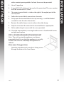
Housing dimensions
•
The appliance is designed to fit into a standard 600mm wide housing unit
with minimum internal dimensions as shown.
600mm is to the underside of the work top when the appliance is built under,
or to the underside of the panel above, when the appliance is installed into a
tall housing unit.
547mm
568mm
20mm
585
560mm MIN
WIDTH
KICK BOARD
5m
m
6m
59
56
PLINTH
m
550mm MIN
DEEP
CABINET
LEG
590mm MIN
600mm MIN
WORK TOP
(UNDERSIDE)
CIA GLASS
TOP OF FAS
588mm TO
BRACKET
OF FASCIA
P
TO
TO
mm
WALL
12mm
GAP IN
PLINTH
INSTALLATION
Do not lift the appliance by the door handle.
WALL
FLOOR
1. When installed in a typical
600mm deep built in housing unit, the false back should be removed from
the housing unit to provide the necessary depth for installation.
2. When the false back is removed, it is normally the case that the support
shelf for the appliance leaves a gap between the back edge and the wall of
approximately 80mm.
3. If no gap occurs between the back edge of the shelf and the wall behind
13.500
20
INSTALLATION
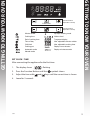
STEP 1 : PREPARE INSTALLATION