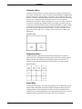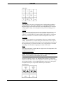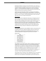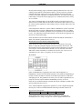
1
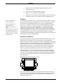
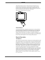
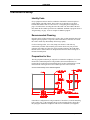
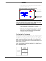
CRESTRON
Contents
Series 3000 Touchpanels
1
Description .......................................................................................................................... 1
Functional Description ........................................................................................... 1
Physical Description............................................................................................... 3
Configuration Differences ...................................................................................... 5
Leading Specifications ......................................................................................................... 6
Installation/Setup ................................................................................................................. 7
Identity Code.......................................................................................................... 7
Recommended Cleaning......................................................................................... 7
Preparation for Use................................................................................................. 7
Hardware Hookup................................................................................................... 8
Configuring the Touchpanel................................................................................... 9
Programming ..................................................................................................................... 15
Reserved Join Numbers ........................................................................................ 15
Workshop Versus SIMPL Windows...................................................................... 15
Problem Solving................................................................................................................. 19
Troubleshooting ................................................................................................... 19
Further Inquiries .................................................................................................. 20
Syntax .................................................................................................................. 20
Return and Warranty Policies............................................................................................. 21
Merchandise Returns / Repair Service .................................................................. 21
CRESTRON Limited Warranty ............................................................................ 21
Operations Guide - DOC. 8094B
Contents • i
CRESTRON
Series 3000 Touchpanels
Description
Functional Description
The Series 3000 Touchpanels are 9.6 inch (23.9 cm) passive matrix touchscreen
control panels for the CRESNET II remote control system (herein referred to as the
CRESNET II system). There are 12 Series 3000 configurations available. Six of the
12 touchpanels offer 256 color display and are commonly known as ColorTouch.
The remaining six touchpanels offer 256 shades of grayscale display and are
commonly known as BriteTouch. ColorTouch and BriteTouch are available in
lectern-mount and adjustable tiltcase configurations. Configuration selection is
based on application requirements. Refer to “Configuration Differences” on page 5
for a more detailed description of each.
The purpose of a ColorTouch and BriteTouch Series 3000 unit is to replace hardwired panels in either a CRESNET II or an RS-232 based control system. The
touchpanel is capable of replacing large, complicated panels with a series of simpler
screens, each specific to the control problem at hand. Thus, very large numbers of
functions can be made available to the user without the confusion associated with
hardware panels of that complexity. Series 3000's icons, graphics, and text can
dramatically increase any user's comprehension of the control environment.
Devices, functions, and control zones are quickly organized and more easily
accessed. The Series 3000 Touchpanels offer:
Operations Guide - DOC. 8094B
•
256 color display (for ColorTouch only)
•
256 shades of grayscale display (for BriteTouch only)
•
pop-up sub panels to reduce memory requirements, providing optimal
speed and performance
•
multiple button, slider control, and icon configurations
•
up to 999 functions and 96 screens
•
imported photographs, drawings, and icons
•
support for downloadable fonts - proportional and non-proportional
•
foreign language text
Series 3000 Touchpanels • 1
CRESTRON
•
RS-232 interface for stand-alone applications (lectern-mount
configurations only)
•
optional feature buttons adjacent to touchpanel
•
printout of screen designs on standard printer
•
Position Lock feature provides durable support of panel at any angle of
inclination between 0 and 70 degrees (tiltcase configurations only).
Software
Have a comment about
Crestron’s software?
Direct software related
suggestions and/or
complaints to Crestron via
email
([email protected]). Do
not forward any queries to
this address. Instead refer to
“Further Inquiries” on page
20 for assistance.
VisionTools™ for Windows (VTW), a design and programming Windows™-based
software, permits the creation of unlimited control screen variations incorporating
two and three-dimensional graphics and text. A set of pages which make up a
project can be designed for each Series 3000 Touchpanel application. Each page
contains objects such as custom control graphics, two and three-dimensional
buttons, sliders, and digital readouts which allow the user to interface with the
CRESNET II system. The project is uploaded to the touchpanel and programmed
into the flash PROM. The touchpanel uses the programmed project until another set
is uploaded from the PC. The PC may be disconnected from the rack or panel
except during reprogramming. For additional software information, consult the help
file available on the VTW installation disks.
Position Lock Button
The position lock button is centrally located at the front of the base on Series 3000
adjustable tiltcase touchpanels. These touchpanels permit incremental angle
positions indicated by audible clicks. Range of motion is adjustable for user comfort
and can vary from zero inclination to 70 degrees from horizontal. Thus the user can
position the touchscreen to a comfortable angle, just as a microphone can be
repositioned for each speaker. The comfortable angle is herein referred to as user
position. The position lock guarantees that once a user position is established or
locked, the angle will not degrade from repeated presses on the touchscreen.
The touchscreen is free to move up from the horizontal to an incremental angle.
Grasp the touchscreen with a hand at each side and gently tilt up to a comfortable
position. To activate position lock, slightly reverse the motion until the touchpanel
stops moving. Correct hand placement is shown below. The touchscreen is now set
into user position.
Hand Position for Tilting Touchpanel to Vertical
Once in user position, position lock is activated which means the touchscreen can
not be forced to the horizontal position without depressing the position lock button.
The touchscreen is still free to tilt up; a new user position is established at each
increment or audible click.
2 • Series 3000 Touchpanels
Operations Guide - DOC. 8094B
CRESTRON
The position lock button needs to be depressed before the touchscreen can be
returned to the horizontal position. To depress the button, slightly position the
touchscreen in the vertical direction with two hands, avoiding any tilting. The
position lock button can be depressed with one hand; the touchscreen can be tilted
down to the horizontal position with the other, shown below.
Hand Position for Tilting Touchpanel to Horizontal
Feature Buttons
ColorTouch and BriteTouch configurations with the letter “B” in their suffix have
seven feature buttons located to the left of the touchpanel screen. The buttons are
identified with numbers one through seven from top to bottom. These buttons are
hard-coded join numbers that serve as “hot keys” for repetitive functions. For
example, assign a feature button’s join number to a frequently used subpage. Create
the subpage on every page of the project. Thus, the subpage can be recalled with the
touch of a single button regardless of the current page being displayed.
Physical Description
Touchpanels
The 9.6 inch (23.9 cm) touch sensitive viewing screen is located on the front of each
Series 3000 Touchpanel. The electronic hardware is housed in a high impact, black
molded plastic enclosure for the adjustable tiltcase configurations, shown after this
paragraph. These touchpanels are designed to be placed on a counter and possess a
hinged base which can tilt from 0 to 70 degrees. Depress the button located at the
front of the base when pivoting the touchpanel to the horizontal position. A 6-pin,
6-position RJ11 modular jack is located at the rear of the adjustable tiltcase base.
Use the cable assembly (supplied) to connect the touchpanel to the CN-RJ11
(supplied), which attaches directly to the CRESNET II network. Aside from display
color, the only difference between the six tiltcase touchpanels is that configurations
with the letter “B” in their suffix have seven feature buttons on the front panel
adjacent to the touchscreen. The buttons are used as “hot keys” for repetitive
functions. Also, the “/1M” suffix indicates a memory upgrade available on two of
the six tiltcase panels.
Operations Guide - DOC. 8094B
Series 3000 Touchpanels • 3
CRESTRON
Physical Views of Tiltcase Series 3000 Touchpanels (CN-RJ11 not shown)
The lectern mount configurations, shown below, are denoted with the letter “L” in
their suffix. They are housed in a black metal box topped with a plastic cover. The
four-pin network and nine-pin RS-232 connector ports are located on the rear of the
panel. Aside from display color, the only difference between the six lectern mount
touchpanels is that configurations with the letter “B” in their suffix have seven
feature buttons on the front panel adjacent to the touchscreen. Also, the “/1M”
suffix indicates a memory upgrade available on two of the six lectern panels.
Physical Views of Lectern Series 3000 Touchpanels
Interface Module: CN-RJ11
NOTE: All tiltcase Series 3000 touchpanels are supplied with a cable assembly
that connects to the CN-RJ11 (supplied). Pinout information is provided in this
section of the Operations Guide. If the assembly must be mutilated in any way,
Crestron cannot guarantee the behavior of the touchpanel. The product may not
function accordingly, as stated in this Operations Guide.
CRESTRON’s CN-RJ11 is a network one-to-one converter that interfaces 4-wire
CRESNET and modular devices. The converter is housed in a black enclosure with
silk-screened top panel, shown after this paragraph. A 4-pin network connector is
located on one side of the unit. A 6-position, RJ11 modular telephone jack is located
on the opposite side. At the shorter sides of the CN-RJ11, the enclosure extends to
form feet at a right angle to the side. There are three holes per foot for inserting
screws to further stabilize the unit.
4 • Series 3000 Touchpanels
Operations Guide - DOC. 8094B
CRESTRON
Physical Views of the CN-RJ11
TOP VIEW
SIDE VIEW (RJ11 CONNECTOR)
SIDE VIEW (4-PIN CONNECTOR)
6-Pin Jack Pinout (for CN-RJ11)
PIN #
SIGNAL
COLOR
1
+24 V (Network)
WHT
2
3
+24 V (Network)
Y (Data)
BLK
RED
4
5
6
Z (Data)
GND (Network)
GND (Network)
GRN
YEL
BLU
#1
TAB (VISIBLE, ON TOP)
Configuration Differences
There are 12 Series 3000 configurations available and selection depends on color
versus grayscale display, type of installation (tiltcase or lectern mount) and whether
physical buttons for repetitive functions are desired. A configuration is defined by
one of two prefixes, CT- or LC-, and one of six suffixes, no suffix, B, BL, L, /1M,
and L/1M. The CT- or LC- prefix identifies the touchpanel as having either a 256
color display or a 256 grayscale display, respectively. No suffix indicates an
adjustable tiltcase configuration; these units are moveable and can tilt. The “B”
suffix identifies the touchpanel as having feature buttons. The "L" suffix identifies
the touchpanel as a lectern mount. The “/1M” suffix identifies the touchpanel as
having its memory upgraded to 1 Mbyte. Refer to the table below for a concise
listing of each Series 3000 configuration.
Series 3000 Touchpanel Configurations
CONFIGURATION
Operations Guide - DOC. 8094B
DISPLAY
INSTALLATION
FEATURE
MEMORY
BUTTONS
CT-3000
256 Color
Movable and can tilt
None
256 Kbytes
CT-3000/1M
CT-3000B
256 Color
256 Color
Movable and can tilt
Movable and can tilt
None
Seven
1 Mbyte
256 Kbytes
CT-3000L
CT-3000L/1M
256 Color
256 Color
Lectern mount
Lectern mount
None
None
256 Kbytes
1 Mbyte
CT-3000BL
LC-3000
256 Color
256 Grayscale
Lectern mount
Movable and can tilt
Seven
None
256 Kbytes
256 Kbytes
LC-3000/1M
LC-3000B
256 Grayscale
256 Grayscale
Movable and can tilt
Movable and can tilt
None
Seven
1 Mbyte
256 Kbytes
LC-3000L
LC-3000L/1M
256 Grayscale
256 Grayscale
Lectern mount
Lectern mount
None
None
256 Kbytes
1 Mbyte
LC-3000BL
256 Grayscale
Lectern mount
Seven
256 Kbytes
Series 3000 Touchpanels • 5
CRESTRON
Leading Specifications
The table below provides a summary of leading specifications for the Series 3000
Touchpanels. Dimensions and weight are approximations rounded to the nearest
tenth unit.
Leading Specifications for Series 3000 Touchpanels
SPECIFICATION
DETAILS
Power Requirements
12 Watts, 24 VDC 0.5 Amp
CRESNET Power Factor
12 Watts
Version 4.20.03 or later
CRESNET II Workshop
CRESNET II Operating System
VisionTools for Windows
SIMPL Windows
Memory
3.11.18 or later
Version VTW 10.7.1 or later
Version 1.0 or later
256 Kbytes flash memory for CT-3000,
CT-3000B, CT-3000L, CT-3000BL, LC-3000,
LC-3000B, LC-3000L, & LC-3000BL
1 Mbyte flash memory for CT-3000/1M,
CT-3000L/1M, LC-3000/1M, & LC-3000L/1M
CT-3000, CT-3000B, CT-3000/1M,
LC-3000, LC-3000B, & LC-3000/1M
Dimensions & Weight
(without CN-RJ11)
CN-RJ11
Dimensions & Weight
CT-3000L, CT-3000BL, CT-3000L/1M,
LC-3000L, LC-3000BL, & LC-3000L/1M
Dimensions & Weight
Height: 8.6 in (212.8 cm)
Width: 11.2 in (28.5 cm)
Depth: 7.0 in (17.8 cm)
Weight: 5.5 lb (2.5 kg) for CT- configurations
Weight: 5.3 lb (2.4 kg) for LC- configurations
Height: 2.0 in (5.0 cm)
Width: 3.3 in (8.3 cm)
Depth: 1.2 in (3.0 cm)
Weight: 0.4 lb (0.2 kg)
Height: 8.3 in (21.0 cm)
Width: 12.8 in (32.4 cm)
Depth: 1.6 in (4.0 cm)
Weight: 5.0 lb (2.3 kg) for CT- configurations
Weight: 4.7 lb (2.1 kg) for LC- configurations
View Screen Dimensions
Height: 5.8 in (14.7 cm)
Width: 7.7 in (19.6 cm)
View Screen Resolution
View Screen Display
640 x 480 pixels
Dual-Scan Passive Matrix LCD
View Screen Illumination
View Screen Touch Screen
Backlit Fluorescent
Resistive Membrane
As of the date of manufacture, the Series 3000 Touchpanels have been tested and
found to comply with specifications for CE marking.
6 • Series 3000 Touchpanels
Operations Guide - DOC. 8094B
CRESTRON
Installation/Setup
Identity Code
Every equipment and user interface within the CRESNET II network requires a
unique identity code (ID CODE). These codes are recognized by a two-digit
hexadecimal number from 03 to FE. Refer to “Configuring the Touchpanel” on
page 9 for instructions on setting the unit's ID CODE. The ID CODE of the unit
must match the ID CODE specified in the CRESNET II SIMPL-I program. Refer to
“Programming” on page 15 for an example of SIMPL-I program.
Recommended Cleaning
Keep the surface of the touchscreen free of dirt, dust, or other materials that could
degrade optical properties. Long term contact with abrasive materials can scratch
the surface which may detrimentally affect image quality.
For best cleaning results, use a clean, damp, non-abrasive cloth with any
commercially available non-ammonia glass cleaner. Bezels may not provide a
complete water-tight seal. Therefore, apply cleaning solution to the cloth rather
than the surface of the touchscreen. Wipe touchscreen clean and avoid ingress of
moisture beneath panels.
Preparation for Use
The only preparation that may be required is to mount the touchpanel. If a lectern
mount Series 3000 touchpanel is being installed, the cutout dimensions are
required. Refer to the lectern cutout details below for these configurations. Cutout
measurements in the figure have been rounded up to the nearest 1/8 inch.
Lectern Cutout Detail for Series 3000 Touchpanels
If the tiltcase configuration is being mounted to a flat surface, locate the mounting
holes on the “foot” of the touchpanel. Refer to the mounting details, shown after
this paragraph. Mount the touchpanel with four #6-32 hardware (not supplied).
Operations Guide - DOC. 8094B
Series 3000 Touchpanels • 7
CRESTRON
Mounting Detail for Tiltcase Series 3000 Touchpanel
Hardware Hookup
Due to configuration differences (between lectern and tiltcase models), the hookup
diagram differs among Series 3000 touchpanels. Complete the following steps in
the order provided to ensure proper installation of the unit.
1.
Before making any connections, review latest revision of network
interconnection drawing (Doc. 5411) or, if necessary, the network
modular cable requirements (Doc. 5682).
2.
Connect the touchpanel to the CRESNET II network via a CRESNET
II network cable, shown below, and appropriate interface module.
Recommended CRESNET II Network Cable, Part No. CRE-2S18218
#18 AWG Stranded Wire
2x Twisted Pairs
NOTE: Wire is available from Liberty
Wire & Cable (719) 260-0061.
CN-RJ11 OR
ANY LECTERN
MOUNT
CONFIGURATION
•
CNRACK OR
CNRACK-D
OR CNMS
A supplied cable assembly (P/N 15717) with 6-position, 6-pin
connectors on each end connects the tiltcase configuration touchpanel
to the CN-RJ11. Connect the CN-RJ11 to the CRESNET II system via
the network cable.
Typical Connection Diagram for Tiltcase Configurations
NOTE:
UNITS IN THIS ILLUSTRATION
ARE NOT DRAWN TO SCALE.
CABLE ASSEMBLY
(P/N 15717)
CONNECT TO CNMS,
CNRACK, OR CNRACK-D
Refer to the CRESNET II
Network Cable drawing in
this section of the Guide.
SIDE VIEW OF TILTCASE CONFIGURATION
8 • Series 3000 Touchpanels
Operations Guide - DOC. 8094B
CRESTRON
•
Connect the lectern mount configuration directly to the CRESNET II
system via the network cable.
Typical Connection Diagram for Lectern Mount Configuration
CONNECT TO SERIAL
PORT OF COMPUTER
Use only for direct connection to PC
to load panels without network.
CONNECT TO CNMS,
CNRACK, OR CNRACK-D
Refer to the CRESNET II Network Cable
drawing in this section of the Guide.
NOTE: Network termination points are available at the control system power
supply. Network units may also be daisy-chained together. Refer to the latest
revision of the CRESNET II reference manual section on CNPWS power supplies
(Doc. 8091) for wire gauge specifications and connection details.
3.
Connect the lectern mount configuration to the serial port of the PC
via the port labeled RS-232. Cable assembly is not supplied.
4.
Apply power to the touchpanel and observe illumination of the touchsensitive screen. The touchpanel enters RUN MODE and displays a
loaded panel page. To enter SETUP MODE and not RUN MODE,
hold a finger to the touchscreen as power is applied. The user may
configure the unit while in SETUP MODE.
Configuring the Touchpanel
To configure the unit, it may be necessary to access a series of setup screens prior to
viewing run-time screens that are loaded into the touchpanel for normal operation.
The Main Menu for configuring the touchpanel appears when a finger is held to the
touchscreen as power is applied. Remove your finger when the message "SETUP
MODE" appears on the touchscreen. Holding a finger to the touchscreen for five
seconds after the "SETUP MODE" message is displayed sets the brightness to high
and the contrast to a safe value.
Upon entering SETUP MODE, the Main Screen, shown below, displays four
buttons: TOUCH SCREEN CALIBRATION, DIAGNOSTICS, SETUP, and SAVE
SETUP AND RUN PROGRAM.
Main Menu
Operations Guide - DOC. 8094B
Series 3000 Touchpanels • 9
CRESTRON
Calibration Menu
Calibration of the touchscreen is required if the active touch area of a button does
not coincide with the button's image. Select the TOUCH SCREEN CALIBRATION
button to display the Calibration Menu, shown below. The Calibration Menu offers
the choice to initiate calibration with the Perform Calibration button or return to the
previous screen with the Return to Main Menu button. Choose an option by
touching the correct button. When touching the screen, be as accurate as possible. If
you proceed to calibrate the touchpanel, the screen prompts you with the message
"Touch Screen Calibration Menu" nearly centered on the display. Another message,
"Touch Upper Left Corner", appears in the upper left corner. Touch the corner of
the screen to initiate calibration. Another message, "Touch Lower Right Corner",
appears in the lower right corner. Touch the corner of the screen to return to the
Main Menu.
Calibration Menu
Diagnostics Menu
The DIAGNOSTICS button from the Main Menu should only be used under
supervision from a CRESTRON technical support representative during telephone
support. The options available from the Diagnostics Menu, shown below, are
numeric in nature and their interpretation is beyond the scope of this manual.
Diagnostics Menu
Setup Menu
To obtain the Setup Menu, shown after this paragraph, select and hold the SETUP
button from the Main Menu until the Setup Menu is displayed. Many options for
setting parameters of the touchpanel are available from the Setup Menu and are
explained in the following paragraphs. After setup parameters have been set, select
the Return button, located at the lower right corner of the Setup Menu.
10 • Series 3000 Touchpanels
Operations Guide - DOC. 8094B
CRESTRON
Setup Menu
Brightness
Screen brightness may need to be altered because of ambient light conditions or
personal preference. Three buttons, Brightness Low, Brightness Medium, and
Brightness High, located in the bottom row of the Setup Menu may be selected to
assign brightness setting. Current brightness setting is shown in light gray text .
Contrast
Screen contrast may need to be altered because of ambient light conditions, panel
temperature, or personal preference. Two contrast buttons, Contrast << and
Contrast >>, located in the two left-most columns of the middle row of the Setup
Menu may be held down for continuous and smooth adjustment of the screen.
Save Setup
It is advisable to regularly save setup parameters if the user is satisfied with the
settings. If parameters are saved, the settings are restored in the event of a power
failure. The Save Setup button located just above the Return button in the corner of
the Setup Menu may be selected at any time to save setup parameters. The button
text changes color from black to light gray text while in save mode.
Return
Select the Return button, located at the lower right corner of the Setup Menu, after
setup parameters have been set.
Backlight Timeout Menu
NOTE: Display backlight requires warm-up time. A display reaches 80% of its
final level in five minutes and full brightness in 20 minutes.
The touchpanel display hardware life can be lengthened by turning off the backlight
when the touchpanel is inactive. The Backlight Timeout button is located in the
middle row of the third column of the Setup Menu. Selection of this button changes
the touchpanel display to reveal the Backlight Menu, shown below. The length of
touchpanel inactivity can be specified to minimize power utilization.
Backlight Menu
Operations Guide - DOC. 8094B
Series 3000 Touchpanels • 11
CRESTRON
BACKLIGHT TIMEOUT is displayed on the Backlight Menu. This setting turns
the backlight off when the touchpanel is inactive for a specified time frame (shown
in minutes). When the touchpanel is activated, the last screen to be displayed
reappears. A two minute BACKLIGHT TIMEOUT is shown in the illustration.
Minutes can vary from 0 to 120, where 0 disables the timeout. Down and up arrow
buttons decrease and increase the timeout, respectively.
Although the STX POWER DOWN TIMEOUT is displayed on the Backlight
Menu, its functionality is disabled for Series 3000 Touchpanels. After the timeout
parameter is set, touch the SAVE TIMEOUTS button in the lower left corner of the
menu to save the new settings. Touch the RETURN button, located in the bottom
right corner of the screen, to display the Setup menu.
Panel Tracking
Panel tracking is a useful communication feature between touchpanels when more
than one touchpanel exists on the network. Panel tracking is enabled when the
Panel Track button, centrally located in the top row of the Setup Menu, is selected.
Selection is indicated with light gray text. When enabled, a given touchpanel
maintains communication in such a way that a page change to any touchpanel on
the network forces the same page change to all enabled touchpanels. Panel tracking
is disabled when the Panel Track button is deselected. When disabled a given
touchpanel does not respond to page changes made to other touchpanels on the
network. Panel tracking is factory set with the Panel Track button deselected.
Interface Menu
The touchpanel communicates with a CRESNET II system to activate other controls
or to display feedback from components within the system. The communication
interface must be correctly specified or communication will not occur. To set
communication parameters select the Interface button located in the upper left
corner of the Setup Menu and display the Interface Menu, shown below.
Interface Menu
The CRESNET network identity number (NET ID) is displayed in the upper-most
rectangle of the Interface Menu. NET ID is the two-digit hexadecimal number
represented by ## in the figure for illustrative purposes. The hexadecimal number
can range from 03 to FE and must correspond to the NET ID set in the SIMPL-I
program of the CRESNET II system. Matching NET IDs between touchpanel and
VisionTools for Windows program is required if data is to be successfully
transferred or new touchpanel screens are to be loaded. NET ID is factory set to 03.
Two side-by-side buttons beneath the hexadecimal display, < Cresnet ID and
Cresnet ID >, decrease and increase the NET ID by one, respectively.
The touchpanel usually communicates with a CRESNET II system. Occasionally the
touchpanel can be used in a local demo mode where it merely displays various
menus, but does not communicate with CRESNET II system. In local mode, the
12 • Series 3000 Touchpanels
Operations Guide - DOC. 8094B
CRESTRON
directory buttons change pages, but buttons requiring feedback do not work. Two
centrally located buttons on the Interface Menu, Local and Cresnet II, determine
communication mode. Select Local to set the touchpanel into demo mode and
Cresnet II for normal CRESNET II communication mode. Text within the selected
button changes color from black to light gray text. Communication mode is factory
set to Cresnet II.
Two side-by-side buttons, RS-232 On and RS-232 Off, are located just above the
Return to Previous Menu button at the bottom of the Interface Menu. RS-232 is just
for external control applications. Panel loading is always available; RS-232 does not
have to be on.
If the touchpanel is utilized in a system without a CRESNET II system, ensure that
the RS-232 button is selected. Additional RS-232 parameters must be set with the
RS-232 Menu since alternative parameters may be required for successful transfers
to a PC. Text within the selected button changes color from black to light gray text.
RS-232 On is the default setting.
Select the Return to Previous Menu button, located at the bottom of the Interface
Menu, after interface parameters have been set.
RS-232 Menu (Lectern-Mount Configurations Only)
Select the RS-232 button, located at the top of the second column of the Setup
Menu, to change the touchpanel display to the RS-232 Menu, shown below. The
RS-232 Menu specifies four parameters required for the touchpanel to use its RS232 serial port. Ten baud rate buttons, labeled 110, 150, 300, 600, 1200, 2400,
4800, 9600, 19200, and 38400, are available for selection. Also, select seven or
eight data bits; none, odd, or even parity; one or two stop bits.
RS-232 Menu
RTS/CTS handshaking is supported by the Series 3000 Touchpanels. If
handshaking is desired, select the RTS/CTS button. If no hardware handshaking is
needed, select the Off button. Selections for all RS-232 parameters are indicated
with light gray text. The parameters are factory set to 38.4 Kbd, eight data bits, no
parity bits, and one stop bit. Handware handshaking is factory set to Off.
Select the Save and Return button, located at the bottom of the RS-232 Menu, after
RS-232 parameters have been set.
RS-232 Protocol
Series 3000 Touchpanels support panel operation via a host computer through the
RS-232 port. Crestron recommends that the following serial data format is set.
Suggested Serial Data Format
Baud Rate: 38400
Data Bits: 8
Parity: None
Stop Bits: 1
These settings may be altered via the RS-232 Menu when configuring the
touchpanel, however, doing so may prevent Crestron supplied software from
Operations Guide - DOC. 8094B
Series 3000 Touchpanels • 13
CRESTRON
operating with the touchpanel. Low baud rates will cause the panel to appear
unresponsive. For example, at 300 baud, a single button press (and release)
generates 12 characters and requires more than 0.333 of a second to send. Delays as
short as 0.1 of a second are generally considered perceptible and somewhat
annoying.
Command Format - Command format for all items sent to or from the touchpanel
is very simple. All items are ASCII strings terminated by a <cr>. Line feed
characters are ignored, thus <cr><lf> or <lf><cr> are also acceptable line
terminators. When the touchpanel sends a line, it is always terminated with
<cr><lf>.
For all strings, the first character determines command type. Numeric arguments, if
present, are in decimal and separated by commas. No control characters are
embedded in the strings to ease processing the strings with high level languages. Be
careful when using commas in BASIC, because BASIC uses commas for field
separators when reading strings from a file using the INPUT # statement. Since we
are dealing with complete lines, use the LINE INPUT # statement to cure this
problem.
P<#> and R<#> Commands - When in RUN mode, pressing a button (assuming
that it has been joined) generates a six-character code in the format P###<cr><lf>,
where ### is a three-character decimal number in the range of 1 through 999,
providing for up to 999 functions. When the button is released, a similar code is
generated, with an 'R' in place of the 'P'. Given that only one button may be pressed
at a time, an 'R' code always follows a 'P' code. A fixed three-digit format is used to
simplify software on the host.
Codes may be sent to the touchpanel in the same form as they are received. The 'P'
form turns on a function and the 'R' form turns off a function; sending back
information received from the touchpanel (i.e., jumping pins 2 and 3) makes the
buttons momentary. Notice that the touchpanel responds to P and R commands even
when configured for other interface modes. Selecting an RS-232 interface mode
merely enables P and R commands to be issued. In addition, the fixed format is not
required for commands sent to the touchpanel; P1, P01, and P001 are all perfectly
valid commands.
Compared to running on CRESNET II, an RS-232 interface to a personal computer
is slower, provides less features (such as tracking, among others), is less noise
immune (CRESNET uses balanced transmission for high common mode rejection,
RS-232 does not), and requires the user to supply the control logic program in the
PC.
V<chan>,<level> Command - Levels in gauge and slider objects may be set
through the RS-232 port. The command contains both the object channel number
(1-255) and level (0-65535) in decimal separated by a comma. For example,
V6,32768 would set channel 6 to level 128, or half way up.
One quick note on baud rate and smooth ramping. Ramping is accomplished by
sending successive levels to the object. To do this in 64 levels over three seconds,
for example, requires about 576 bytes worth of commands to be sent, and could not
be accomplished at any rate less than 2400 baud. Obviously, ramping several objects
at once requires a baud rate several times as high.
Indirect Text - Series 3000 Touchpanels support a feature that permits the text
field in any user-defined button to be altered on the fly in RUN mode. This is
accomplished by substituting a text pointer for the text in the button. The text
pointer informs the panel to use the contents of a variable that may be dynamically
redefined as the text field for the button. This presents a considerable advantage
over other methods in that changing screens does not destroy information and that
information may be placed in buttons not currently displayed.
14 • Series 3000 Touchpanels
Operations Guide - DOC. 8094B
CRESTRON
The text pointer is a single letter, ‘A’ through ‘Z’ or ‘a’ through ‘z’ preceded by the
“at” symbol (@). If [text…] is omitted, the text field is cleared. If [text…] exists, it
is added to the text field. For example, consider the following string :
@CNow is the time<cr>
@Cfor all good men<cr>
@Cto come to the<cr>
@Caid of the party.<cr>
Assuming that a button with an @C text pointer was being displayed, the contents
of the button would be changed to:
Now is the time
for all good men
to come to the
aid of the party.
NOTE: To clear the text field for this example, type in “@C<cr>”.
As each line is entered, the display is updated. Since the text may be placed in
several different buttons, no boundary checking is done to see if the text fits in the
button. If the text overflows the boundaries, it remains centered about the center of
the button.
Save Setup and Run Program
The Save Setup and Run Program button, located at the upper right corner of the
Main Menu, saves all of the setup information to EEPROM and displays the main
page that has been programmed into your system.
Programming
Reserved Join Numbers
A reserved join number is a feature of the software that enables a designer to create
a button on a page that either calls up the Setup Menu, selects brightness, etc. The
table below provides a list of reserved join numbers available within the software.
Reserved Join Numbers for Series 3000 Touchpanels
JOIN NUMBER
FUNCTION
VALUE
1016
Brightness
Off
1017
1018
Brightness
Brightness
Low
Medium
1019
1023
Brightness
Contrast
High
Up
1024
1035
Contrast
Call up Setup Menu
Down
Not Applicable
Workshop Versus SIMPL Windows
The print date of this Operations Guide occurs so precariously close to the official
release of SIMPL Windows that an exemplary discussion of both programming
methods should coexist. The Workshop is Crestron’s DOS-based programming
Operations Guide - DOC. 8094B
Series 3000 Touchpanels • 15
CRESTRON
software; whereas SIMPL Windows, by virtue of its name, is Windows-based.
Although Crestron will continue to provide support for Workshop queries, there is
no plan to add new features to it. For this reason, Crestron suggests that all new
programming be done with SIMPL Windows.
Workshop
SIMPL is CRESTRON's programming language designated for easy
implementation of the control system requirements. The objects that are used in
SIMPL are called symbols. A basic touchpanel SIMPL program is shown below in
block diagram form.
Series 3000 SIMPL Program
The CRESNET II Workshop is designed to simplify the various operations needed
to program and run a CRESNET II control system. The series of screen displays,
shown below, are accessible from the "Define Network" option of the SIMPL-I
Menu in the CRESNET II Workshop.These screens are shown to clarify the means
of assigning signal names for the SIMPL program in the previous illustration.
Workshop Screens (1 of 2)
Workshop Screens (2 of 2)
16 • Series 3000 Touchpanels
Operations Guide - DOC. 8094B
CRESTRON
SIMPL Windows
SIMPL Windows was designed to supersede the CRESNET II Workshop. It
provides a well-designed graphical environment with a number of workspaces (i.e.,
windows) in which a programmer can select, configure, program, test, and monitor
a CRESNET control system.
NOTE: The following description assumes that the reader has some knowledge of
SIMPL Windows. If not, please refer to the extensive help information provided
with the software.
Using the same example in the previous Workshop section, the following
paragraphs and illustrations provide insight to a small portion of a CRESNET
control system developed with SIMPL Windows.
To begin, the programmer should envision the system in block diagram form,
shown below.
Block Diagram of CRESNET Control System
Use the Configuration Manager workspace in SIMPL Windows to select and
configure all the devices that need to be included into the system. For this example,
a CT-3000 must be added to the system and its NET ID must be set to 11, shown
below.
Graphical System View in SIMPL Windows’ Configuration Manager
Use the Programming Manager workspace in SIMPL Windows to select symbols
and assign their respective signals. For this example, a touchpanel symbol was
added automatically when the CT-3000 was added to the system. Assign signals as
shown after this paragraph.
Operations Guide - DOC. 8094B
Series 3000 Touchpanels • 17
CRESTRON
Graphical Detail View of a Touchpanel in SIMPL Windows’ Programming Manager
For this overly simplified example, there is only one logic symbol used. Use the
Programming Manager to select and assign signals to the Interlock symbol, shown
below.
Graphical Detail View of an Interlock in SIMPL Windows’ Programming Manager
The signals from the Interlock are used as feedback into the touchpanel as well as to
drive the relay card that resides in the first slot of the CNMS. Use the Programming
Manager to select and assign signals to the Relay card symbol, shown below.
Graphical Detail View of the Relay Card in SIMPL Windows’ Programming Manager
18 • Series 3000 Touchpanels
Operations Guide - DOC. 8094B
CRESTRON
Problem Solving
Troubleshooting
The table below provides corrective action for possible trouble situations. If further
assistance is required, please contact a CRESTRON technical support
representative.
Series 3000 Troubleshooting
TROUBLE
POSSIBLE
CAUSE(S)
CORRECTIVE ACTION
Use Performance Viewport (via CRESNET
Touchpanel Touchpanel is not
communicating to the Workshop or VTW) to poll the network. Verify
does not
network connection to the touchpanel.
network.
function.
Verify touchpanel is in "CRESNET II" mode as
defined in the Interface Menu of the
"Configuring the Touchpanel".
Touchpanel is not
Confirm that power is supplied to the network.
receiving network
power.
Touchpanel is
Enter SETUP MODE and recalibrate.
incorrectly calibrated.
Touchpanel Incorrect network
Touch screen to remove message and verify
is not
wiring.
correct wiring to all connectors.
responding Touchpanel ID is not Touch screen to remove message and enter
and screen set to match the NET Performance Viewport (via CRESNET
displays
ID in the SIMPL
Workshop or VTW) to poll the network. Verify
"Network
program.
that the NET ID for the touchpanel is properly
Poll Error"
set to match the SIMPL program.
message.
Touchpanel ID not
Enter Performance Viewport (via CRESNET
unique, two or more Workshop or VTW) to poll the network. Verify
units share same ID. that each ID is used once.
Touchpanel Backlight timeout has Touch screen to reactivate.
display is
elapsed.
dark.
Screen brightness is Enter SETUP MODE and alter screen
improperly set.
brightness from the Setup Menu.
Unexpected Touchpanel is
Enter SETUP MODE and recalibrate.
response
incorrectly calibrated.
from
touchpanel.
Operations Guide - DOC. 8094B
Series 3000 Touchpanels • 19
CRESTRON
Further Inquiries
If after reviewing this Operations Guide for the Series 3000 Touchpanels, you
cannot locate specific information or have questions, please take advantage of
Crestron's award winning technical support team by calling:
•
In the US and Canada, call Crestron’s corporate headquarterrs at 1888-CRESTRON [1-888-273-7876] or 1-201-767-3400.
•
In Europe, call Crestron International at +32.15.730.974.
•
In Asia, call Crestron Asia at +852.2341.2016.
•
In Latin America, call +525.574.15.90.
For local support from exclusive Crestron factory-trained personnel call:
•
In Australia, call Soundcorp at +613.941.61066.
•
In New Zealand, call Amber Technologies at +649.410.8382.
Syntax
The following syntax codes are provided for compatibility purposes only. It is a
sample of SIMPL-C programming for the block diagram example illustrated in
“Programming” on page 15.
NET.ID <03 to FE>: CTP-3000
i1
o1
“
i4
o4
20 • Series 3000 Touchpanels
= <relay1>
= <relay1_fb>
= “
“
= <relay4>
=<relay4_fb>
\i1 refers to join# of touchpanel button
Operations Guide - DOC. 8094B
CRESTRON
Return and Warranty Policies
Merchandise Returns / Repair Service
1.
No merchandise may be returned for credit, exchange, or service
without prior authorization from CRESTRON. To obtain warranty
service for CRESTRON products, contact the factory and request an
RMA (Return Merchandise Authorization) number. Enclose a note
specifying the nature of the problem, name and phone number of
contact person, RMA number, and return address.
2.
Products may be returned for credit, exchange, or service with a
CRESTRON Return Merchandise Authorization (RMA) number.
Authorized returns must be shipped freight prepaid to CRESTRON,
Cresskill, N.J., or its authorized subsidiaries, with RMA number
clearly marked on the outside of all cartons. Shipments arriving
freight collect or without an RMA number shall be subject to refusal.
CRESTRON reserves the right in its sole and absolute discretion to
charge a 15% restocking fee, plus shipping costs, on any products
returned with an RMA.
3.
Return freight charges following repair of items under warranty shall
be paid by CRESTRON, shipping by standard ground carrier. In the
event repairs are found to be non-warranty, return freight costs shall
be paid by the purchaser.
CRESTRON Limited Warranty
CRESTRON ELECTRONICS, Inc. warrants its Cresnet II products, denoted by a
"CN" prefix model number, to be free from manufacturing defects in materials and
workmanship for a period of three (3) years from the date of shipment to purchaser.
Disk drives and any other moving or rotating mechanical parts are covered for a
period of one (1) year. CRESTRON warrants all its other products for a period of
one year from the defects mentioned above, excluding touchscreen display
components which are covered for 90 days. Incandescent lamps are completely
excluded from Crestron's Limited Warranty. CRESTRON shall, at its option, repair
or replace any product found defective without charge for parts or labor. Repaired or
replaced equipment and parts supplied under this warranty shall be covered only by
the unexpired portion of the warranty.
CRESTRON shall not be liable to honor warranty terms if the product has been
used in any application other than that for which it was intended, or if it has been
subjected to misuse, accidental damage, modification, or improper installation
procedures. Furthermore, this warranty does not cover any product that has had the
serial number altered, defaced, or removed.
This warranty shall be the sole and exclusive remedy to the purchaser. In no event
shall CRESTRON be liable for incidental or consequential damages of any kind
(property or economic damages inclusive) arising from the sale or use of this
equipment. CRESTRON makes no other warranties nor authorizes any other party
to offer any warranty, expressed or implied, including warranties of merchantability
for this product. This warranty statement supersedes all previous warranties.
Operations Guide - DOC. 8094B
Series 3000 Touchpanels • 21