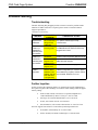
1
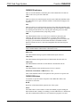
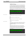
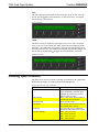
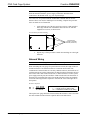
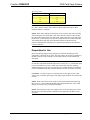
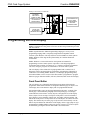
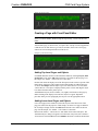
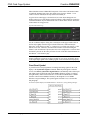
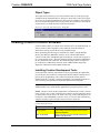
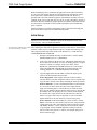
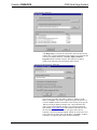
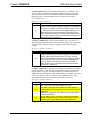
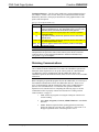
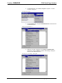
Crestron CNRACKX CNX Card Cage System Contents CNX Card Cage System: CNRACKX 1 Description .......................................................................................................................... 1 Functional Description............................................................................................ 1 Physical Description ............................................................................................... 2 Leading Specifications ......................................................................................................... 6 Setup.................................................................................................................................... 7 Rack Mounting....................................................................................................... 7 Network Wiring...................................................................................................... 8 Preparation for Use ................................................................................................. 9 Programming the LCD Display........................................................................................... 10 Front Panel Editor ................................................................................................ 10 Creating a Page with Front Panel Editor................................................................ 11 Object Types ........................................................................................................ 13 Loading Crestron Control Software .................................................................................... 13 Installing Crestron Development Tools ................................................................. 13 Initial Setup.......................................................................................................... 14 File Types............................................................................................................. 16 Obtaining Communications................................................................................... 18 Troubleshooting Communications......................................................................... 20 Loading the System Program ................................................................................ 23 Testing the Permanent Memory Image .................................................................. 24 Loading Touchpanels............................................................................................ 24 Updating the Control System ................................................................................ 25 Problem Solving................................................................................................................. 28 Troubleshooting ................................................................................................... 28 Further Inquiries ................................................................................................... 28 Return and Warranty Policies ............................................................................................. 29 Merchandise Returns / Repair Service................................................................... 29 CRESTRON Limited Warranty............................................................................. 29 Operations Guide - DOC. 8133 Contents • i Crestron CNRACKX CNX Card Cage System CNX Card Cage System: CNRACKX Description Functional Description The CNRACKX is an integral part of Crestron’s new generation of control system technology featuring the newest series of Ethernet/LAN compatible control systems. The CNRACKX is a modular “card cage” control system offering the ultimate in flexibility and customization. In addition to the CNXCPU (central processing unit), the unit has the capacity for 15 expansion cards. The variety of CNX expansion cards provides a very high degree of functionality and therefore, this type of system is suitable for relatively large systems. The CNRACKX requires an external power supply, CNPWS-75 (sold separately). Expansion Slots The 15 open “card cage” slots accept any combination of CNX expansion cards. A slot for the CNXCPU that optionally features Crestron’s exclusive DPA (Direct Processor Access) port for Ethernet/LAN expansion of the control network. This port provides high-speed access directly to the processor while maintaining bandwidth network connections. The DPA permits 10BaseT and is ready to support Firewire, ATM, 100BaseT and other future protocols. LCD Display An 80-character (two 40-character lines) LCD display is located on the front panel to provide extended features, status information, and troubleshooting indications. Network Analyzer To further assist with troubleshooting, the CNRACKX contains Crestron’s patentpending network analyzer to continuously the integrity of the Crestron network for wiring faults and marginal system performance or other network errors. For more information on how to use the network analyzer, refer to the SIMPL™ Windows help file and use the index to search for “Network Analyzer”. Operations Guide - DOC. 8133 CNX Card Cage System: CNRACKX • 1 CNX Card Cage System Crestron CNRACKX Physical Description The CNRACKX is housed in a black enclosure with silk-screened labels on the front panel. On the front panel there is a single RS-232 computer port, standard LEDs, two reset buttons, a reverse LCD display with menu function and selection buttons, and a row of slot status LED indicators. The rear panel provides 15 open CNX expansion card slots and the CNXCPU. On the CNXCPU, there are two Cresnet connectors, a single RS-232 computer port, and two LEDs. The LAN/DPA port is available when the optional CNXENET expansion card is installed as part of the CNXCPU. CNRACKX Physical Views 19.00 in (48.26 cm) P PW WR R C O M P U T E R P R O F E S S I O N A L C O N T R O L P R O C E S S O R LAN NET RXD ERR TXD HW-R LNK SW-R ERR M ME EN NU U INTERFACE CONTROL CARD SLOT 1 2 3 4 5 6 7 8 9 10 11 12 13 14 15 B BK KLLTT 5.20 in (13.21 cm) CNRACKX CRESTRON FRONT PANEL 17.16 in (43.58 cm) CNXCPU CONTROL PROCESSOR PWR NET LAN COMPUTER DPA 24 Y Z G C R E S N E T CRESTRON REAR PANEL Four rubber feet (supplied) can be affixed to the bottom of the CNRACKX to provide stability and to prevent slippage when mounted on a flat surface. The unit may also be rack mounted by attaching metal flanges, known as ears (supplied), to each end. CNRACKX Ports There is only one CNRACKX port, labeled COMPUTER, on the front panel. The other ports on the rear are part of the CNXCPU: COMPUTER Computer Connectors FRONT PANEL COMPUTER C O M P U T E R REAR PANEL These 9-pin DB9 female connectors (one on the front panel and one on the CNXCPU) are used when programming with a PC. A standard DB9 female (PC end) to DB9 male (CNRACKX end) straight-through serial cable (not supplied) is used to communicate with either COMPUTER port. The ports are electrically connected and are modem compatible. The modem cable is not included. 2 • CNX Card Cage System: CNRACKX Operations Guide - DOC. 8133 Crestron CNRACKX CNX Card Cage System CRESNET Cresnet 4-Wire and 6-Pin Connectors 24 Y Z G C R E S N E T On the CNXCPU, there are two network connectors: 4-wire and modular. The 4-wire male connector (typical Crestron network port labeled 24 Y Z G) and 6-pin RJ-type connector are used for expansion to Cresnet and SmarTouch peripherals. The total maximum load rating depends on the expansion slot load. The ports are wired in parallel. NOTE: If using the 4-wire connector, review the latest revision of the Cresnet Network Interconnect Drawing (Doc. 5411). NOTE: If using the modular connector, review the latest revision of the Crestron Network Modular Cable Requirements (Doc. 5682). Most 6-conductor phone cables are wired in a crisscross fashion and are not compatible with Crestron equipment. LAN/DPA LAN/DPA Connector LAN DPA This 8-pin RJ-type port on the CNXCPU is available when the optional CNXENET Expansion Card is installed. Refer to the CNXENET Operations & Installation Guide (latest revision of Doc. 8129) for further information. Operations Guide - DOC. 8133 CNX Card Cage System: CNRACKX • 3 CNX Card Cage System Crestron CNRACKX CNRACKX Indicators There are 22 LED indicators on the front panel of the CNRACKX. The other two LEDs on the rear are part of the CNXCPU: PWR These two LEDs (one on the front panel and one on the CNXCPU) illuminate when the CNRACKX receives power from the CNPWS-75 External Power Supply (sold separately). NET These two LEDs (one on the front panel and one on the CNXCPU) illuminate when the CNXCPU is processing data or communicating with system hardware. Examples are a button pressed at the local or a network panel, data being sent out of either serial port, or a permanent memory image being created. ERR This LED illuminates when one or more error conditions are detected by the CNXCPU. This may be the result of hardware or software failure, hardware incompatibility with software definitions, or a programming error. To read the error message(s), press the MSG (from the Default Info Menu) and MENU DOWN buttons to examine the error(s). The LED extinguishes after the last message has been read. NOTE: The next four LEDs are active only if the optional CNXENET Expansion Card is installed and the CNRACKX is connected to a LAN. RXD (LAN) This LED illuminates during reception of Ethernet data by the CPU slot. TXD (LAN) This LED illuminates during transmission of Ethernet data from the CPU slot. LNK (LAN) This LED illuminates when there are attachments to the Ethernet network. ERR (LAN) This LED illuminates when an Ethernet protocol error is detected. INTERFACE CONTROL CARD SLOT (1 – 15) These LEDs illuminate when a CNX expansion card is present in a respective slot. CNRACKX Buttons Two buttons are provided on the front panel of the CNRACKX. Refer to the description of each below: HW-R Depression of this button initiates physical reset of the system. SW-R The SW-R button is used to initiate a restart of the SIMPL program. Holding the button while the unit is starting (or restarting), sets the CNRACKX to a default mode where the communications baud rate is set to 9600 and no program is executed. 4 • CNX Card Cage System: CNRACKX Operations Guide - DOC. 8133 Crestron CNRACKX CNX Card Cage System CNRACKX LCD Display The front panel of the CNRACKX incorporates a reverse mode (yellow on black) LCD display, shown below. The screen contains two lines with 40 characters per line; it is used to extend features and gain access to the system including the SIMPL program. Menu buttons partially surround the display. To the right of the display there are four menu “selection” buttons. These buttons permit the user to navigate through the menus and control the backlight brightness of the display. Beneath the display there are six menu “function” buttons. These buttons offer extended features of the CNRACKX. Refer to “Programming the LCD Display” on page 10 for details. Default LCD Display Menu Selection Buttons MENU This button returns the screen display to the menu default state. This button advances the screen display by one page. This button returns the current screen display to its previous state. BKLT This button alters the screen backlight brightness. Menu Function Buttons PANEL This button displays a programmable interface offering command text, indirect text, and hierarchical screen structure. An example of this display is provided in the Programming the LCD Display section. The menu is subject to programming; a sample application is portrayed. INFO This button displays a default Info Menu, shown below. System information, including the loaded SIMPL program version, types of CNX expansion cards installed in the card slots, the Cresnet devices detected, the Ops/ROM version, and the communication settings, is displayed. While the COM menu is displayed, depressing the or menu selection buttons changes the system baud rate. Default Info Menu Operations Guide - DOC. 8133 CNX Card Cage System: CNRACKX • 5 CNX Card Cage System Crestron CNRACKX MSG This button displays system alarms and error messages. If one or more errors are present, press the menu selection button to see the next message. An example system message is shown below. Message Example TIME This menu can only be obtained by entering the correct access code. The default access code is 1234. The default Time Menu, shown after this paragraph, permits alterations to the CNRACKX date and time. Selecting a date/time parameter from the menu increments it by one. Additional incremental or decremental changes can then be done by depressing the and menu selection buttons, respectively. Default Time Menu Leading Specifications The tables below provide a summary of leading specifications for the CNRACKX. Dimensions and weight are rounded to the nearest hundredth unit. Leading Specifications of the CNRACKX SPECIFICATION Power Requirements DETAILS 24VDC from the CNPWS-75 External Power Supply (not supplied), Load Factor for the CNRACKX with CNXCPU only (no other 1 SIMPL Windows expansion cards) is 5 watts. Version 1.30.01 or later with the addition of 2 CNX Upgrade File Reset Buttons LCD Display Dimensions & Weight of smwlib49.exe and smwlib49.txt. Version 5.07.00w or later.3 HW-R (permits physical reset of system) & SW-R (restarts SIMPL program). (1) reverse mode (yellow on black) LCD back light; (2) lines, (40) characters per line. Height: 5.20 in (13.21 cm) Width: 19.00 in (48.26 cm) Depth: 8.31 in (21.12 cm) Weight: 8.00 lb (3.60 kg)4 6 • CNX Card Cage System: CNRACKX Operations Guide - DOC. 8133 Crestron CNRACKX CNX Card Cage System 1 CAUTION: The total load factor of the CNRACKX depends on the expansion cards installed. Add the combined power requirements of all of the cards to be installed and add 5-watts for the CNRACKX and CNXCPU. Do not exceed 75 watts for total load factor of a single CNRACKX. 2 The latest software versions can be obtained from the Software Downloads page (SIMPLWIN Library) of Crestron’s website (www.crestron.com). New users are required to register in order to obtain access to the FTP site. 3 Filenames for CNX update files have a .UPZ extension and can be obtained from the Software Downloads page (OPSYS Library) of Crestron’s website. 4 Listed weight is for CNRACKX with CNXCPU and no other expansion cards. Leading Specifications of the CNRACKX Card Slots SLOT 1 through 15 CPU DETAILS (15) open "card cage" slots accept any CNX Expansion Card. Card slot for CNXCPU. As of the date of manufacture, this unit has been tested and found to comply with specifications for CE marking. NOTE: This device complies with part 15 of the FCC rules. Operation is subject to the following two conditions: (1) these devices may not cause harmful interference, and (2) these devices must accept any interference received, including interference that may cause undesired operation. Setup Rack Mounting WARNING: To prevent bodily injury when mounting or servicing this unit in a rack, you must take special precautions to ensure that the system remains stable. The following guidelines are provided to ensure your safety: 4 The unit should be mounted at the bottom of the rack if it is the only unit in the rack. 4 When mounting this unit in a partially filled rack, load the rack from the bottom to the top with the heaviest component at the bottom of the rack. 4 If the rack is provided with stabilizing devices, install the stabilizers before mounting or servicing the unit in the rack. NOTE: If rack mounting is not required, rubber feet are provided for table-top mounting or stacking. On the underside of the unit, apply two of the feet at the rear corners and the remaining two approximately one inch from the front corners. Operations Guide - DOC. 8133 CNX Card Cage System: CNRACKX • 7 CNX Card Cage System Crestron CNRACKX NOTE: Reliable grounding of rack mounted equipment should be maintained. Particular attention should be given to supply connections other than direct connections to the branch circuit. (e.g., use of power strips). Two “rack ears” are provided with the CNRACKX so that the unit can be rack mounted. These ears must be installed prior to mounting. Complete the procedure below to attach ears to CNRACKX: 1. At the left-front side of the unit, position a rack ear so that its drilled holes align with the four unused holes and secure the ear with four supplied #6-32 screws, as shown below. Ear Attachment for Rack Mounting SECURE WITH FOUR #6-32 SCREWS PER EAR (SUPPLIED) 2. Repeat step 1 of this procedure to attach the remaining ear to the rightfront side. Network Wiring NOTE: This section only applies to those applications using 4-wire Cresnet wiring. When calculating the wire gauge for a particular network run, the length of the run and the load factor of each network unit to be connected must be taken into consideration. If network units are to be daisy-chained on the run, the load factor of each network unit to be daisy-chained must be added together to determine the load factor of the entire chain. If the network unit is a home-run from a Crestron system power supply network port, the load factor of that network unit is the load factor of the entire run. The length of the run in feet and the load factor of the run should be used in the following resistance equation to calculate the value on the right side of the equation. Resistance Equation R < 40,000 L x LF Where: R = Resistance (refer to table below) L = Length of run (or chain) in feet LF = Load factor of entire run (or chain) The required wire gauge should be chosen such that the resistance value is less than the value calculated in the resistance equation. Refer to the table below: 8 • CNX Card Cage System: CNRACKX Operations Guide - DOC. 8133 Crestron CNRACKX CNX Card Cage System Wire Gauge Values RESISTANCE (R) WIRE GAUGE 4 16 6 18 10 20 15 22 NOTE: All network wiring must consist of two twisted-pairs. One twisted pair is the +24V conductor and the GND conductor and the other twisted pair is the Y conductor and the Z conductor. NOTE: When daisy chaining network units, always twist the ends of the incoming wire and outgoing wire which share a pin on the network connector. After twisting the ends, tin the twisted connection with solder. Apply solder only to the ends of the twisted wires. Avoid tinning too far up or the tinned end becomes brittle and breaks. After tinning the twisted ends, insert the tinned connection into the network connector and tighten the retaining screw. Repeat the procedure for the other three network conductors. Preparation for Use Refer to the hookup diagram on the next page. Aside from attaching power last, complete the connections in any order. The serial cable to the PC may be attached to the DB9 connector of the CNXCPU or to the DB9 connector on the CNRACKX front panel. CAUTION: To prevent overheating, do not operate this product in an area that exceeds the recommended ambient temperature of 104°F (40°C). Consideration must be given if installed in a closed or multi-unit rack assembly since the operating ambient temperature of the rack environment may be greater than the room ambient. Contact with thermal insulating materials should be avoided on all sides of the unit. CAUTION: Care must be given to connecting units to the supply circuit so that wiring is not overloaded. The ratings on the supply input should be considered in this concern. NOTE: Refer to the latest revision of the Cresnet Network Interconnect Drawing (Doc. 5411) or Crestron Network Modular Cable Requirements (Doc. 5682) when making connections to the port labeled CRESNET. NOTE: Since the plug on the power supply cord is used to disconnect power from the unit, the socket-outlet shall be installed near the equipment and shall be easily accessible. Operations Guide - DOC. 8133 CNX Card Cage System: CNRACKX • 9 CNX Card Cage System Crestron CNRACKX Hookup Connections for CNRACKX CNXCPU CONTROL PROCESSOR PWR NET LAN COMPUTER TO SERIAL PORT ON PC (PARALLEL DB9 CONNECTOR ALSO ON CNRACKX FRONT PANEL) DPA 24VDC 50W TO ANY STS OR CRESNET NETWORK DEVICE 24 TO ETHERNET OR LOCAL AREA NETWORK WITH OPTIONAL CNXENET CARD Y Z G C R E S N E T CRESTRON Programming the LCD Display NOTE: The following description assumes that the reader has some knowledge of SIMPL™ Windows®. If not, please refer to the extensive help information provided with the software. SIMPL (Symbol Intensive Master Programming Language) is an easy-to-use programming language that is completely integrated and compatible with all Crestron system hardware. The objects that are used in SIMPL are called symbols. SIMPL Windows offers drag and drop functionality in a familiar Windows® environment. SIMPL Windows is Crestron Electronics development environment for programming Crestron control systems. It provides a well-designed graphical environment with a number of workspaces (i.e., windows) in which a programmer can select, configure, program, test, and monitor a Crestron control system. The LCD display of the CNRACKX is preprogrammed with a certain level of diagnostic, testing, and network device information. Assuming the CNRACKX is connected to a PC running SIMPL Windows, a LCD display programming utility (Front Panel Editor) can be accessed. This editor enables a programmer to program multi-level pages under the PANEL (left-most, function) button on the LCD display. Front Panel Editor The LCD display on a CNRACKX has different pages that are defined by the programmer. Menu function buttons are assigned to different pages or objects. The LCD display has a 2x40 character display with six-programmable buttons. In Front Panel Editor, pages are designed and added to the panel. A sample of the default page is shown after this paragraph. Each front panel page is one display (2x40 characters) and can have as many objects as the physical size of the display allows (objects can not overlap). The top line of the panel is used for informative object displays, such as headings, indirect text, bar graphs, and time and date. The bottom line of the panel is for objects that are accessed by the six buttons below the display. The buttons only access the page or object whose field is directly over the button. Objects added to the bottom line of the display can have page jumps or logic programming in SIMPL Windows that cause specific events to occur. These objects are initiated by pressing the function button that is associated with it. 10 • CNX Card Cage System: CNRACKX Operations Guide - DOC. 8133 Crestron CNRACKX CNX Card Cage System Default Front Panel Page Creating a Page with Front Panel Editor NOTE: The creation of a front panel page is discussed in this section. For more details, consult the SIMPL Windows help file. Specifically, search on Front Panel Editor. Assume that a page, as shown below, is required. The concept of such an application is that the user can then choose a given device and then, from a lower-level page, control one or more transport functions of the device. Example of a Front Panel Page Adding Top-Level Pages and Objects Use SIMPL Windows and access the Front Panel Editor by selecting Project | Edit Front Panel. Click on the Add button and enter a new name for the new page. For this sample, use “Menu1 – Choose Device” as the name. Double-click inside the display area of the front panel on the screen to open the “Edit Panel Object” dialog box. This sample requires that headings be added to the page, so choose Text Object from the Object Type area. In the Inactive Text field, enter “Choose Device”. The object is displayed on the panel. Click on and drag the object to its desired location on the panel, top row. Add additional objects (VCR, LaserDisc, CD, Lights, and Volume) to the page by double-clicking in the display area where the object is to appear. Repeat the procedure in the previous paragraph; place objects over the appropriate button. Adding Lower-Level Pages and Objects Lower-level pages can be added for each of the objects on the bottom row of the page just created. For the purposes of this sample, one lower-level page is added for the VCR object. Simply click on the Add button and enter a new name for the new page. For this sample, use “Menu2 – VCR Control” as the name. Return to the “Menu1 – Choose Device” and double-click on the VCR object. The “Edit Panel Object” dialog box appears. From the Menu Jump field, select “Menu2 – VCR Control” and click OK. Select the Simulate check box to make the Front Panel Operations Guide - DOC. 8133 CNX Card Cage System: CNRACKX • 11 CNX Card Cage System Crestron CNRACKX Editor simulate an actual CNRACKX front panel. Click on the VCR function button to enable the simulated page jump. The display clears, because “Menu2 – VCR Control” has been named, but no objects have been added yet. A typical VCR Control page, as shown below, has a text object that appears as a header on the top row of the display and objects that are control functions assigned to each function button. Objects in the bottom row are shown in the inactive state (none of the buttons are being pressed). Typical VCR Control Page Use the “Edit Panel Object” dialog box to add objects to this page. Double-click on the first object, play. From the Digital Channel field in the “Edit Panel Object” dialog box, scroll down to or enter “1”. In the Active Text field, enter “PLAY” as the button’s active text. Therefore, when the function button associated with digital channel 1 (the VCR button) is pressed, the active text is displayed as a visual cue that the button is pressed. Do the same procedure for each of the other function buttons in the “Menu2 – VCR Control” page. NOTE: Digital channels are also referred to as “join numbers”. Join numbers are numeric identifiers assigned to an object or button. It is necessary to identify objects so the input/output signals of the SIMPL program can be named and routed properly. Front Panel Symbol A powerful tool to assist programmers in naming and routing signals for the LCD display is the Synchronize Signals command. While the panel appears on the PC screen, select Panel | Synchronize Signal Names to automatically name all the input and output signals for the front panel in the SIMPL Windows program. To display the signal names, double-click on Slot-08 : CNX LCD Front Panel that is available from the Central Control Modules Directory in the Program View of SIMPL Windows’ Program Manager. The symbol appears in Detail View, as shown after this paragraph. Front Panel Symbol Displayed in SIMPL Windows’ Detail View of Programming Manager 12 • CNX Card Cage System: CNRACKX Operations Guide - DOC. 8133 Crestron CNRACKX CNX Card Cage System Object Types The sample discussed in the previous sections utilizes only one of the object types available from the “Edit Panel Object” dialog box, shown below. These object types are not new to Crestron programmers; the same types are available in VisionTools™ Pro. For a detailed description of these types refer to the VisionTools™ Pro help file. Use the glossary or search function to locate the information. Object Type Area in the “Edit Panel Object” Dialog Box Loading Crestron Control Software Crestron control software is available in an electronic form; via CD-ROM, email, or from Crestron’s website. Regardless of how and from where the software is obtained, this section provides the necessary installation steps. Before performing the following set of instructions, obtain a "straight through" RS-232 cable that has a DB9 male connector on one end and a DB9 female connector on the other. "Straight through" means that pin 1 on the male end goes to pin 1 on the female end, etc. The male end plugs into the port labeled COMPUTER on the CNRACKX or the CNXCPU. The female end plugs into the serial port of a PC. If the PC has a DB25 male connector, obtain a DB9 to DB25 adapter (the adapter has a DB9 male end and a DB25 female end). Installing Crestron Development Tools Crestron provides customers with software tools for programming the CNRACKX. Even if only the control software is being loaded into the hardware and there are no plans to do any programming, some Crestron development software must be installed on the PC. Currently, Crestron programming is accomplished with the use of the following development tools listed in the table after this paragraph. NOTE: If the intent is to load software developed by someone else, then install SIMPL Windows only. Install all three applications to program systems as well. NOTE: The latest version of these applications is available from Crestron’s website (www.crestron.com). Crestron ControlCD also contains a version (which may not be as current as the website version). To obtain a free copy of the CD-ROM, please call Crestron at 1-888-CRESTRON [1-888-273-7876] or 1-201-767-3400. Alternatively, complete a literature request from the Crestron website to obtain one. Crestron Development Tools DEVELOPMENT TOOL SIMPL Windows VisionTools Pro DEAL for Windows Operations Guide - DOC. 8133 DESCRIPTION Used to program the CNRACKX. Used to design touchpanel layouts and to program SmarTouch Systems. Used for learning (using the optional CNXLIR) and maintaining IR driver files. CNX Card Cage System: CNRACKX • 13 CNX Card Cage System Crestron CNRACKX Before installing any tools, confirm that all applications such as Microsoft Office, etc. are closed. The website and CD provide instructions for installing the various development tools. When initiating a custom install from the CD, the user is presented with a list of the software programs, documentation, and other resources available on the CD. For each item, the user can set or clear a checkbox to the left of the item to direct the installation program whether to install that component onto the user’s hard drive. The number of items installed determines how much hard disk space is required. Each development tool contains a help file that can be opened from the Help pulldown menu. Refer to these files for additional information. Initial Setup NOTE: For the Ethernet IP setup of the CNRACKX with the optional CNXENET Expansion Card, refer to the CNXENET Operations & Installation Guide (latest revision of Doc. 8129) for further information. To avoid any procedural errors, follow After installing the desired development tool, various job files may be obtained from the steps in the order provided. Crestron or other sources. Using Windows Explorer, complete the following steps. These steps ensure that all job files reside on the hard drive (C:) in the Directory \CRESTRON\PROJECTS\MYJOB. 1. Navigate to the SIMPL directory on the hard drive. Assume that the default install directory is C:\CRESTRON. 2. Create a new folder for the project files. Although the folder where the files are placed is not critical, it is easier to manage projects if a logical structure is created. For example, create a new folder, called PROJECTS, underneath the CRESTRON directory. Create another folder, called MYJOB, under PROJECTS for the current job. The resulting pathname is C:\CRESTRON\PROJECTS\ MYJOB. 3. Copy the supplied files into the folder created in the last step. The source of the file determines the procedure. From a floppy disk: Most floppies sent from Crestron contain a common directory structure designed to make it easier to organize files. Copy the entire contents of the disk(s) including the directory structure. From an .EXE file: If a job is downloaded from the Crestron website or is received via email, all files may have been compacted into a single, self-extracting archive. This archive has an .EXE extension. First, copy the .EXE file into the directory stated in step 1, then run the file (double-click). The program asks for a location for the extracted files. In this case, simply browse for the same directory where the archive was copied. Once files are extracted, it is wise to retain the original .EXE file in case files need to be restored at any point. From a .ZIP file: If the downloaded job is from Crestron’s website, BBS or is received via e-mail, all files may have been compressed into a single archive file with a .ZIP extension. If the program was created with SIMPL Windows 1.30.01 or later, this file was created with the “Copy Program” feature of SIMPL Windows, which provides the option to archive the project to a .ZIP file. An example dialog box is shown on the next page. 14 • CNX Card Cage System: CNRACKX Operations Guide - DOC. 8133 Crestron CNRACKX CNX Card Cage System “Copy Program” Dialog Box After Begin Copy is selected, the selected files will be archived to the example file C:\Crestron\Simpl\Programs\example.zip. For this ZIP file to be used by SIMPL Windows, select File | Import Archived Program from the Crestron Viewport. This will present a dialog similar to the following, after selecting the ZIP to import: “Import an Archived Program” Dialog Box The job may be copied to any folder or directory, and the User IR, Macro, and SIMPL+ files will be copied to the proper directories. If a version of SIMPL Windows lower than 1.30.01 is being used, copy the .ZIP file into the job directory stated in step 1, then extract the files with a program called WinZip. Obtain a copy of this program from their website (www.winzip.com) on the internet. Extract the files into the same directory where the archive was copied. Once files are extracted, it is wise to retain the original .ZIP file in case the files need to be restored at any point. The User IR, Macro, and SIMPL+ modules will need to be copied to their proper directories manually. Operations Guide - DOC. 8133 CNX Card Cage System: CNRACKX • 15 CNX Card Cage System Crestron CNRACKX File Types There are quite a few file types involved with Crestron control software. This section explains the different types that might be encountered in each directory. In many cases the supplied software is grouped into a number of subdirectories. The intent is to keep files organized. For example, after copying the files to the hard disk, the directory structure may appear as shown below. Possible Directory Structure “Ops” Subdirectory - The files in this subdirectory contain the CNRACKX operating system with which the program was tested. Ensure that the operating system version currently loaded is equal to or newer than the version included here, so that the program runs properly. For help with uploading an operating system, refer to “Updating the Control System” on page 25. File Types in “Ops” Subdirectory FILE TYPE .upz DESCRIPTION This is a control system file. For more information regarding these files, refer to "Upgrading the Control System". “Programs” Subdirectory - The files in this subdirectory contain the system program. This is the main program that loads into the CNRACKX and determines the exact functionality of the system. File Types in “Programs” Subdirectory FILE TYPE .smw .bin .smp .log .sig 16 • CNX Card Cage System: CNRACKX DESCRIPTION This is the SIMPL Windows program file. It contains the source code for the main system program. This file is required if changes need to be made to the program. This is the "executable code" for the CNRACKX. This file is loaded into the CNRACKX and cause it to behave as instructed by the program. This is the SIMPL-C file that is generated from the .smw file when a program is compiled. In SIMPL Windows version 1.18 or lower, this file is what actually gets compiled into the .bin file. In versions after 1.18, this file may or may not be generated and is not required. This is a text file containing information about the last program compilation. It is for reference only and is not needed. In versions after 1.18, this file may or may not be generated. This file contains information required by Test Manager (see SIMPL Windows help for more information) for debugging programs in realtime. It is generated each time the program is compiled. Operations Guide - DOC. 8133 Crestron CNRACKX CNX Card Cage System “Userdb” Subdirectory - The files in this subdirectory are "user database" IR drivers, which are needed to interface with certain IR-controlled devices in the system. These differ from "Crestron database" IR drivers in that the former are included as part of a Crestron Database release, available from our website (www.crestron.com). File Types in “Userdb” Subdirectory FILE TYPE DESCRIPTION .ir This is a user IR driver file. It is needed during the convert/compile process in order to properly compile the program. If recompilation of the program is necessary, use the Import Program option or copy any .ir files received into the default user database directory (see SIMPL Windows help for more information). Alternatively, set the SIMPL Windows userdb directory to the directory where the macros exist. In SIMPL Windows, this is accomplished from the Directories tab by selecting Edit > Preferences. “Usrmacro” Subdirectory - The files in this subdirectory are "user macros," or special sub-programs that are integral parts of the main program. These differ from "Crestron macros" in that the former are supplied as part of the development software. File Types in “Usrmacro” Subdirectory FILE TYPE .umc DESCRIPTION This is a user macro file. It is needed during the convert/compile process in order to properly compile the program. To recompile the program, use the Import Program option or copy any .umc files received into the default user macro directory (see SIMPL Windows help for more information). Alternatively, set the SIMPL Windows usermacro directory to the directory where the macros exist. In SIMPL Windows, this is accomplished from the Directories tab by selecting Edit > Preferences. “UsrSPlus” Subdirectory - The files in this subdirectory contain the User SIMPL+ modules used in this system. Note that to recompile the program, use the Import Program option or copy the .USP and .USH files received into the default user SIMPL+ directory. Alternatively, set the SIMPL windows user SIMPL+ directory to the directory where the .USP and .USH files exist. In SIMPL windows, this is accomplished from the Directories tab by selecting Edit > Preferences. File Types in “UsrSPlus” Subdirectory FILE TYPE .usp .ush .uf .csz Operations Guide - DOC. 8133 DESCRIPTION User SIMPL+ source code module. This file gets compiled by the SIMPL+ environment and also is editable by the user. User SIMPL+ header file. This file details how SIMPL Windows should model the gate as a symbol (i.e. how many inputs, how many outputs, etc.). User SIMPL+ compiled file. This contains the "executable" SIMPL+ code for the CNRACKX. Crestron SIMPL+ archive. This archive contains all of the SIMPL+ executable code (from both user modules and crestron modules) that the Transfer Program dialog will send to the CNRACKX. CNX Card Cage System: CNRACKX • 17 CNX Card Cage System Crestron CNRACKX Touchpanel Directory - The files in this subdirectory contain touchpanel projects (for example, “Vt3501” and “Vt3502” in the previous illustration titled “Possible Subdirectory Structure”). Each project describes the exact graphical nature of the panel to which it uploads. File Types in Touchpanel Subdirectory FILE TYPE DESCRIPTION .vtp This is the only VisionTools Pro (VTPro) file required for a given project. It replaces the .prj, .pgf, and graphic (.bmp, .pcx, etc.) files that were part of VisionTools for Windows (VTW) projects. .hex This is the compiled touchpanel project file. This file is uploaded to the panel itself. .lgc Logic files for existing SmarTouch products, like ST-1500/1500C, that use VTW. .vti and .vtl Logic files for existing SmarTouch products, like ST-1500/1500C or ST-1550/1550C that use VTPro. .bmp, .pcx, These are graphic files that are needed by VTW for recompiling touchpanel projects. or .dib NOTE: In this example, the “Vt3501” and “Vt3502”directories represent two touchpanels that are part of the entire remote control system. Please consult the connection sheets or other supplied information to determine which directory corresponds to a given touchpanel. Obtaining Communications NOTE: If the optional CNXENET Expansion Card is installed, communications can be obtained with the CNRACKX over TCP/IP. The CNXENET Operations & Installation Guide explains how to set up the control system for communications over Ethernet as well as communicating with the CNRACKX. Refer to the CNXENET Operations & Installation Guide (latest revision of Doc. 8129) for further information. Before attempting to upload the program files into the CNRACKX, it is necessary to first establish communication between the CNRACKX and a PC. There are two ways of communicating with the CNRACKX, either via the COMPUTER port (RS-232 serial communications) or via Ethernet if the optional CNXENET Expansion Card is installed. Prior to completing the following steps, be sure the communication cable is properly connected as described in “Loading Crestron Control Software” on page 13. 18 • CNX Card Cage System: CNRACKX 1. Make sure that no programs accessing the COM port of the PC to be used are running. 2. Select Start | Programs | Crestron | SIMPL Windows to start SIMPL Windows. 3. SIMPL Windows responds with an opening splash screen and may display the “What do you want to do?” dialog box. Click on the ‘x’ in the upper right-hand corner of the dialog box to close it. Operations Guide - DOC. 8133 Crestron CNRACKX CNX Card Cage System 4. As illustrated below, select Tools | Viewport to open the “Crestron Viewport” dialog box. Accessing the Viewport 5. From the Setup menu, verify that Auto Baud Search is checked. Refer to illustration below. Verifying Auto Baud Search 6. While the Viewport is displayed, select Setup | Communications (alternatively, depress Alt+D) to open the “Port Settings” dialog box and refer to the illustration below. Accessing the “Port Settings” Dialog Box Operations Guide - DOC. 8133 CNX Card Cage System: CNRACKX • 19 CNX Card Cage System Crestron CNRACKX 7. Select the appropriate connection type (RS-232 for a PC connection through the COMPUTER port of the CNRACKX or CNXCPU or TCP/IP through the Ethernet via the optional LAN/DPA port). Verify that the proper COM port is selected. Set the baud rate to 38400, the parity to none, the data bits to 8, and the stop bits to 1. Refer to the dialog box shown on the next page for the remaining settings. Click on the OK button to save the settings and close the dialog box. “Port Settings” Dialog Box 8. Select Diagnostics | Check Operating System Version (alternatively, depress F5) from the Viewport. The viewport may display a window as it scans various baud rates. Eventually, a message should appear in the Incoming section showing a version number. Such a response indicates that communications have been established. If a “No Communications with Rack” error message appears, proceed to “Troubleshooting Communications” below. If the baud rate of the CNRACKX was something other than 38400, then the software automatically adjusts the baud rate to 38400. Troubleshooting Communications NOTE: This section covers troubleshooting communications of the CNRACKX via RS-232 to the COMPUTER port. For troubleshooting Ethernet communications of the CNRACKX with the optional CNXENET Expansion Card, refer to the CNXENET Operations & Installation Guide (latest revision of Doc. 8129) for further information. 20 • CNX Card Cage System: CNRACKX Operations Guide - DOC. 8133 Crestron CNRACKX CNX Card Cage System If communications with the CNRACKX was not established, follow the steps in this section to help remedy the problem. After performing each step, repeat step 7 in “Obtaining Communications” on page 18 again. 1. Try repeating step 7 from “Obtaining Communications” to attempt to establish communications. 2. Verify that the cable being used is correct. It should be a “straightthrough” cable. That is, pin 1 on one end is connected to pin 1 on the other end. Pin 2 connects to pin 2, etc. To work properly, pins 2, 3, and 5 must be connected. 3. Verify that the proper COM port on the PC has been selected. Some computers have more than one COM port; some of which may be internal (e.g., for a modem). If verification can not be made, consult the user’s manual or contact the PC manufacturer. 4. Check the NET and ERR LEDs on the front of the CNRACKX. If either LED is illuminated, unplug the unit and reapply power after a few seconds. If either LED illuminates again, call Crestron technical support. Refer to “Further Inquiries” on page 28. 5. If steps 1 through 4 have failed to result in communications, the last series of steps to perform is an “overload/reset” on the control processor. Complete the following steps to do so: 5a. While the Viewport is displayed, select Functions | Set Baud Rate (alternatively, depress F8) to open the “Set Baud Rate” dialog box. Accessing the “Set Baud Rate” Dialog Box Operations Guide - DOC. 8133 CNX Card Cage System: CNRACKX • 21 CNX Card Cage System Crestron CNRACKX 5b. Set the baud rate to 9600, as shown below. Changing the Baud Rate from the “Set Baud Rate” Dialog Box 5c. Set the CNRACKX to 9600 baud. - Depress and hold the SW-R button on the CNRACKX front panel. - Depress and release the HW-R button on the CNRACKX front panel. - Wait until a message similar to the one below appears in the Viewport. Viewport Message CNRACKX Monitor v5.07.00 * 07/14/99 - interupt serial i/o 512k flash memory, 512k NVRAM, segment =FA00 Press <esc> now to enter debug monitor NOTE: If a computer is not hooked up, wait approximately three to four seconds. - Release the SW-R button. 5d. If the CNRACKX responds, proceed to step 5e. Otherwise, do the following. - Remove power from the CNRACKX. - Depress and hold the SW-R button on the CNRACKX front panel. - Reapply power to the CNRACKX. - Wait until a message similar to the Viewport message above appears. NOTE: If a computer is not hooked up, wait approximately three to four seconds. - Release the SW-R button. 5e. Text messages, as shown below, should appear on the Incoming Window of the viewport. If messages do not appear or they are illegible, verify that the viewport is set to 9600 baud and repeat steps 5a through 5d. If data similar to that shown below appears, perform steps 7 through 11 in “Obtaining Communications” on page 18 before proceeding to the next step. 22 • CNX Card Cage System: CNRACKX Operations Guide - DOC. 8133 Crestron CNRACKX CNX Card Cage System Crestron Viewport - Incoming Window NOTE: The exact text received depends on the given CNRACKX hardware. 5f. Remove power from the unit again and reapply power without holding the RESET button down. Wait a few seconds and perform step 7 in “Obtaining Communications” on page 18. NOTE: If after trying all these procedures, communication can not be established, contact Crestron technical support for assistance. Refer to “Further Inquiries” on page 28. Loading the System Program To load the system program into the CNRACKX, use the Crestron Viewport or the Transfer Program option in SIMPL Windows. For consistency, the steps that follow this paragraph use the viewport. To upload a .BIN file into the CNRACKX, complete the following steps in the order provided: 1. Select Tools | Viewport to open the “Crestron Viewport” dialog box, if it is not already opened. 2. Select File Transfer | Send Program (alternatively, depress Alt+P) to open the “Cresnet Simpl Program” dialog box as shown below. “Cresnet Simpl Program” Dialog Box Operations Guide - DOC. 8133 CNX Card Cage System: CNRACKX • 23 CNX Card Cage System Crestron CNRACKX 3. Use the Browse button to locate the supplied .BIN file. 4. Click the Send Program button to initiate program upload to the CNRACKX. A “Transfer in Progress” dialog box appears, but no response is required. If SIMPL+ files are present and the "SIMPL+ Program(s)" option is checked under "What to Send:", the associated files will be transferred after the program is transferred. NOTE: The permanent memory image is the program stored into flash memory. From the image, the program can be recalled automatically if power to the unit is lost or interrupted. Contrary to their name, a permanent memory image can be overwritten as many times as needed. 5. When a “Query” dialog box appears to create the permanent memory image, click Yes. A “Success” dialog box appears to inform you that the permanent memory image is complete. If the “Failure” dialog box appears, repeat steps 3 and 4. If this does not remedy the problem, call Crestron technical support. Refer to “Further Inquiries” on page 28. NOTE: Clicking the Make Permanent button also creates a permanent memory image but using this button is not normally required. 6. After transferring the program file, click on the Check Program button to ensure that the file loaded properly. The information in the Current Program field of the “Cresnet Simpl Program” dialog box should update and display the file currently loaded. If the information does not update, repeat steps 3 through 5. If this does not remedy the problem, call Crestron technical support. Refer to “Further Inquiries” on page 28. Testing the Permanent Memory Image To test the permanent memory image, complete the following steps: 1. Select Tools | Viewport to open the “Crestron Viewport” dialog box. 2. Unplug the CNRACKX and leave it unplugged for about 10 seconds. 3. Plug the unit in and observe the statistics displayed in the Viewport display field. The program name uploaded into the system also appears. 4. Verify the displayed information against what was originally loaded when the unit was shipped. Loading Touchpanels The CNRACKX may include one or more touchpanels. Each panel must be set to the proper network ID and loaded with a touchpanel project in order to work properly in conjunction with the system program loaded in “Loading the System Program” on page 23. For each panel in the system, a separate .HEX file describing the graphical elements of the panel is required. In some cases, where two or more panels are to be identical in usage, a single .HEX file may be used for multiple panels. To load a touchpanel project into the panel, use the Crestron Viewport or the “Upload Project” function in VisionTools™ Pro. For consistency, the steps that follow this paragraph are using the viewport. To upload a .HEX file into the touchpanel, complete the following steps in the order provided: 24 • CNX Card Cage System: CNRACKX Operations Guide - DOC. 8133 Crestron CNRACKX CNX Card Cage System 1. Verify that the touchpanel to be loaded is connected to the CNRACKX via the appropriate network cable. Also, verify that the touchpanel is set to the proper network ID. (This info should be available in the system connection sheets or directly from the programmer.) 2. Select Tools | Viewport to open the “Crestron Viewport” dialog box, if it is not already opened. 3. Select Diagnostics | Report Network Devices (alternatively, depress F4) and verify that the touchpanel to be loaded reports back and is at the expected network ID. 4. Select File Transfer | Send Touchpanel (alternatively, depress Alt+T) and set the network ID to the ID of the touchpanel to be loaded. 5. Browse for the supplied .HEX file and click the Open button. The file is sent to the CNRACKX and then over the network to the touchpanel. Verify that the panel displays a message saying that the upload is in progress. Updating the Control System The CNRACKX contains an Operating System, a Monitor ROM, and with the optional CNXENET expansion card, a TCP/IP Stack. Although each are separate components, they are packaged together in a “Control System Update File”. Control system update files have the extension .UPZ. It is often necessary to update a control system if new features have been implemented (such as support for new hardware or new language constructs) or if bugs have been corrected. The following procedure is recommended to load a new .UPZ file into the CNRACKX: NOTE: UPZ files only pertain to X generation control systems and are not used for older models such as the CNRACK, CNMS, CNLCOMP-232, or ST-CP. Consult the appropriate documentation for each of these products to perform updates. Establish communications with the CNRACKX by following the steps listed in “Obtaining Communications” on page 18. 1. From the Crestron Viewport, select File Transfer | Update Control System as shown below. Accessing the “Update Control System” Dialog Box Operations Guide - DOC. 8133 CNX Card Cage System: CNRACKX • 25 CNX Card Cage System Crestron CNRACKX 2. The “Update Control System” dialog box, shown below, offers the option to enter the path name of a new update file. If the path name is not known, use the Browse button to navigate to a list of available update files. When browsing, make sure to choose only update files that end with .UPZ. “Update Control System” Dialog Box 3. After a file is selected, the “Update Control System” dialog, as shown below, will query the CNRACKX to determine what versions of the Operating system, Monitor ROM, and TCP/IP Stack are currently running. Example “Update Control System” Dialog Box 26 • CNX Card Cage System: CNRACKX Operations Guide - DOC. 8133 Crestron CNRACKX CNX Card Cage System 4. If the CNRACKX does not have the optional CNXENET Expansion Card, uncheck the TCP/IP Stack option to transfer faster (transferring the stack will not cause any problems). Otherwise, send all of the checked components. To start the transfer, click the Send button. The transfer dialog will inform you of the progress in updating the selected components. 5. As a result of the update, a dialog box similar to below may appear and the SIMPL program (and possibly SIMPL+ modules) must be cleared. “Continue with transfer?” Selection Box 6. Operations Guide - DOC. 8133 Upload the SIMPL program and SIMPL+ modules after the transfer is complete CNX Card Cage System: CNRACKX • 27 CNX Card Cage System Crestron CNRACKX Problem Solving Troubleshooting The table following this paragraph provides corrective action for possible trouble situations. If further assistance is required, please contact a Crestron technical support representative. CNRACKX Troubleshooting TROUBLE Unexpected response from CNRACKX. Green PWR indicator (on CNXRACK or CNXCPU) does not illuminate. Yellow NET indicator (on CNXRACK or CNXCPU) does not illuminate. Red ERR indicator illuminates. POSSIBLE CAUSE(S) CORRECTIVE ACTION Network devices are not communicating with the CNRACKX. CNRACKX is not receiving power. From the Viewport (in SIMPL Windows or VT Pro), poll the network (F4) to verify communication. Loose network connection. SIMPL Windows program is not loaded properly. SIMPL Windows program error. Hardware or software failure, hardware incompatibility with software definitions, or programming Verify that Cresnet cables plugged into CNXCPU and all expansion cards are secure. Depress the SW-R button to restart the SIMPL Windows program. Verify that power supply is properly attached to CNRACKX and the other end is securely plugged into an outlet. Verify the SIMPL Windows program. Verify that hardware configuration matches software configuration (i.e., card is in proper slot as defined by program). Poll the network (F4) via SIMPL Windows or VT Pro. Further Inquiries If after reviewing this Operations Guide, you cannot locate specific information or have questions, please take advantage of Crestron's award winning technical support team by calling: • In the US and Canada, call Crestron’s corporate headquarters at 1-888-CRESTRON [1-888-273-7876] or 1-201-767-3400. • In Europe, call Crestron International at +32-15-50-99-50. • In Asia, call Crestron Asia at +852-2341-016. • In Latin America, call Crestron Latin America at +525-574-15-90. For local support from exclusive Crestron factory-trained personnel call: 28 • CNX Card Cage System: CNRACKX • In Australia, call Soundcorp at +613-941-61066. • In New Zealand, call Amber Technologies at +649-410-8382. Operations Guide - DOC. 8133 Crestron CNRACKX CNX Card Cage System Return and Warranty Policies Merchandise Returns / Repair Service 1. No merchandise may be returned for credit, exchange, or service without prior authorization from CRESTRON. To obtain warranty service for CRESTRON products, contact the factory and request an RMA (Return Merchandise Authorization) number. Enclose a note specifying the nature of the problem, name and phone number of contact person, RMA number, and return address. 2. Products may be returned for credit, exchange, or service with a CRESTRON Return Merchandise Authorization (RMA) number. Authorized returns must be shipped freight prepaid to CRESTRON, Cresskill, N.J., or its authorized subsidiaries, with RMA number clearly marked on the outside of all cartons. Shipments arriving freight collect or without an RMA number shall be subject to refusal. CRESTRON reserves the right in its sole and absolute discretion to charge a 15% restocking fee, plus shipping costs, on any products returned with an RMA. 3. Return freight charges following repair of items under warranty shall be paid by CRESTRON, shipping by standard ground carrier. In the event repairs are found to be non-warranty, return freight costs shall be paid by the purchaser. CRESTRON Limited Warranty CRESTRON ELECTRONICS, Inc. warrants its Cresnet products, denoted by a "CN" prefix model number, to be free from manufacturing defects in materials and workmanship for a period of three (3) years from the date of shipment to purchaser. Disk drives and any other moving or rotating mechanical parts are covered for a period of one (1) year. CRESTRON warrants all its other products for a period of one year from the defects mentioned above, excluding touchscreen display components which are covered for 90 days. Incandescent lamps are completely excluded from Crestron's Limited Warranty. CRESTRON shall, at its option, repair or replace any product found defective without charge for parts or labor. Repaired or replaced equipment and parts supplied under this warranty shall be covered only by the unexpired portion of the warranty. CRESTRON shall not be liable to honor warranty terms if the product has been used in any application other than that for which it was intended, or if it has been subjected to misuse, accidental damage, modification, or improper installation procedures. Furthermore, this warranty does not cover any product that has had the serial number altered, defaced, or removed. This warranty shall be the sole and exclusive remedy to the purchaser. In no event shall CRESTRON be liable for incidental or consequential damages of any kind (property or economic damages inclusive) arising from the sale or use of this equipment. CRESTRON makes no other warranties nor authorizes any other party to offer any warranty, expressed or implied, including warranties of merchantability for this product. This warranty statement supersedes all previous warranties. Trademark Information All brand names, product names, and trademarks are the sole property of their respective owners. Windows is a registered trademark of Microsoft Corporation. Windows95, Windows98 and WindowsNT are trademarks of Microsoft Corporation. Operations Guide - DOC. 8133 CNX Card Cage System: CNRACKX • 29