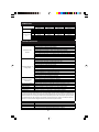
1
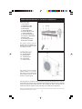
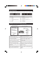
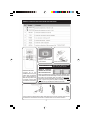
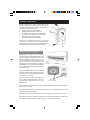
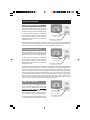
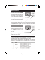
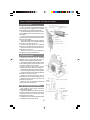
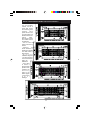
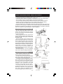
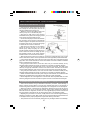
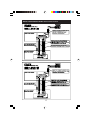
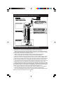
For those who only want the Best!
High Efficiency
Ductless Mini Split System
Air Conditioner / Heat Pump
Owner’s Manual
Thank you for choosing this high quality Pioneer air conditioning / heat pump system for your needs.
To ensure satisfactory operation for many years to come, it is imperative that certain installation and
maintenance procedures must be followed carefully. Installation of your system requires highly
specialized training and certain special tools. Therefore, please hire a well trained technician to perform
the installation tasks. Provide a copy of this manual to the installer to follow the instructions written
herein. Also keep the manual in a safe place for future reference for usage and maintenance
information. If lost or misplaced, please contact your supplier for a downloadable copy.
CONTENTS:
Safety precautions……….................................…………… 1
Names of the major components……..................……… 3
Indoor Unit Display……….....................................……… 4
Remote Controller and Settings..........................……… 5
Modes of Operation...........................................………. 6
Installation Instructions (Location)....................………. 10
Installation Instructions (Indoor Unit)................……… 11
Installation Instructions (Outdoor Unit).............……… 13
Installation Instructions (Electrical)....................……… 15
Final Steps and Startup......................................………
16
Diagnosis...........................................................………
17
Installation Specks.....................................................
17
Wiring Size.................................................................
18
Trouble Shooting.......................................................
18
Maintenance Requirements......................................
19
Limited Warranty.......................................................
20
Installation Notes.......................................................
21
In line with the manufacturer’s policy of continual product improvement, the aesthetic and
dimensional characteristics, as well as the technical data and the accessories of this appliance
may be changed without notice.
SAFETY RULES AND BASIC RECOMMENDATIONS FOR THE INSTALLER
Please read this manual entirely before installing
and using this appliance and follow all instructions
and general safety rules carefully. High voltages
and pressures existing within this unit can cause
serious harm to persons or property or even death.
Only properly licensed and highly trained
technicians should install this appliance. Improper
installation will cause irreversible damages and
serious safety risks.
Do not locate the system components within two
feet of any inflammable substances, pressurized
containers and moisture containing items.
Refrigerant leakage can be dangerous for humans
and animals. Area must be well ventilated in case
of a suspected refrigerant leakage.
Do not discard the packing materials improperly
into the environment. All packing materials are
recyclable. Do not discard the system components
improperly to avoid possible environmental
pollution by chemicals inside.
Installation must be performed according to all
applicable and current national and local codes,
regulations and laws.
During the installation, the area within the indoor
and outdoor sections of this split system must be
restricted to all unauthorized personnel to avoid
any accidents.
Both indoor and the outdoor units must be firmly
fixed to the proper parts of the building’s structure.
Operate and regularly maintain the system as
instructed in this manual. Since not all possible
conditions and situations can be properly outlined
in this manual, as with any electrical appliance,
use common sense and caution during operation
and maintenance. Do not attempt to repair this
appliance without hiring a qualified technician.
Air always contains some level of humidity. Any
air left within the system or entering into the
system will cause insufficient performance and
irreversible internal compressor damage.
Warranty is valid only when the equipment is
installed properly by licensed HVAC contractors
and the warranty registration card must be properly
filled out and sent to the manufacturer.
Installer must carry out cycle tests and monitor
and record of all related operational data before
leaving the scene.
System components must be installed where they
can be accessed for maintenance and repairs easily.
Sufficient clearances must be provided at all
directions for removal of various panels.
Sensitive components in this unit are protected
by a fuse installed on the electronic card located
in the indoor unit. Rating of this fuse is 5 Amps /
250 V. When needed replace with another fuse
with the same rating only.
System carries sufficient refrigerant, charged into
the outdoor unit as shipped. Service valves were
closed. When using the standard accessory piping
kit, there is no need to adjust the included
refrigerant amount. In case the refrigerant lines
are extended or trimmed by more then 5 feet, the
refrigerant amount must also be adjusted up or
down accordingly. System must be properly
evacuated before releasing the refrigerant. All
connections must be checked for leaks.
System power should be attached to the outdoor
unit, through a properly rated independent power
circuit, protected by a properly rated circuit
breaker and a service disconnect switch box,
located near the outdoor unit.
Ensure that the incoming voltage corresponds with
the required power written on the rating plate.
Make all connections tightly and waterproof to
avoid risk of electrical shocks or fire due to
insufficient contact.
Indoor unit removes humidity from the air while
cooling, generating significant amount of
condensate water. The water should be properly
disposed off, through proper drainage piping.
All power wires, breakers and other components
used to supply power to the unit must be approved
for such use and properly rated for the load.
For any other questions or concerns, always
consult with a properly trained HVAC technician.
Do not allow repairs or changes to your system
by unlicensed and untrained persons.
Always disconnect power before servicing.
Contact the dealer for other questions.
1
SAFETY RULES AND BASIC RECOMMENDATIONS FOR THE USER
Please do not attempt to install this product
yourself. Installation is complex and requires high
level of training and very specific tools.
Performance, safety, and longevity levels fully
depend on the quality of the installation.
Do not allow children play with or operate the
system without adult supervision.
Please remember, indoor fan runs continually in
cooling mode, while the compressor cycles on or
off as needed to maintain the set temperature. This
is normal and required for proper sampling of the
room air temperature across the temperature
sensors located in the indoor section. Power
consumed by the indoor unit is totally insignificant
and should not cause any economical concerns.
Owner performed maintenance should be limited
to washing the indoor unit’s air filters and hosing
off the outdoor unit’s heat exchanger regularly. Any
other maintenance and deeper cleaning should be
performed by trained personnel only.
Always disconnect power to the entire system by
turning off the main breaker before cleaning or
maintenance.
Do not discard the packing materials before
assuring the units inside were not damaged during
transportion. All packing materials are recyclable.
Do not discard the system components or packing
improperly to avoid environmental pollution.
Do not use the system for any purpose other then
air conditioning and heating the space it is installed
within.
Operate and regularly maintain the system as
instructed in this manual. Since not all possible
conditions and situations can be properly outlined
in this manual, as with any electrical appliance,
use common sense and caution during operation
and maintenance. Do not attempt to repair this
appliance without hiring a qualified technician.
Do not use the air conditioner without the air filters
properly installed and regularly cleaned, at least
once every 2 weeks or more often as needed.
Ignoring this important factor will cause expensive
repairs and cleaning to the heat exchangers.
External surfaces of the indoor and outdoor units
can be cleaned by warm water and mild soap, while
power is disconnected. Do not drip water inside.
Warranty is valid only when the equipment is
installed properly by licensed HVAC contractors
and the warranty registration card has been
properly filled out and sent to the manufacturer.
If any vibrations, abnormal sounds, smells, smoke
or fumes are noticed, immediately shut down the
power and call a technician for service.
Keep the area near the outdoor unit clean from
snow, mud, leaves and other debris. Do not plant
any bush within the required clearances shown in
the diagrams in the following pages.
Never insert your hand, fingers or any other objects
into any of the openings.
Do not cover the indoor or the outdoor units while
they may be operational or powered on.
Operate the air conditioner only using the remote
controller, except in an emergency, you may also
use the emergency button as mentioned later.
Keep all windows and doors closed while the
system is operating. Excessive humidity in the
room air will cause unit sweat condensate water,
which may drip on your floors and furniture.
Do not allow the cold or hot discharge air to be
blown directly and continually on people, pets,
plants or other sensitive objects.
Use low fan speed mode for quieter operation but
select high fan speed mode for high performance.
For extended unutilized periods, shut down the
power at the breaker. Cover the outdoor unit to
prevent from excessive accumulation of dust and
debris and from other perils. Remove the batteries
from the remote controller.
Do not have this unit installed illegally and without
a required permit from your building department.
Check for compliance with all local codes,
ordinances and homeowners association rules.
Do not use the remote controller too often to turn
the unit on and off. Instead set the thermostat at a
comfortable temperature and leave the system to
perform as programmed automatically to keep the
space at the desired comfort levels.
For any other questions or concerns, always
consult with a properly trained HVAC technician.
Do not allow repairs or changes to your system
by unlicensed and untrained persons.
Turn off the system during thunderstorms.
Contact the dealer for other questions.
2
NAMES AND DESCRIPTIONS OF THE MAJOR COMPONENTS
INDOOR UNIT:
1. Front Panel
2. Standard Air Filter
3. Optional Air Filter
4. LED Display
5. Infrared Receiver
6. Terminal Block Cover
7. Ionizer (Optional)
8. Internal Air Deflectors
9. Emergency Start Button
10.Rating Label
11. Auto Swing Louvers
12.Remote Transmitter
This indoor section must be
installed indoors, preferably on an
external wall, and inside the space
to he heated or cooled.
OUTDOOR UNIT:
13. Air Outlet Grille
14. Rating Label
15. Terminal Cover
16. Liquid Valve
17. Suction Valve
This outdoor section must be
installed outdoors, on a concrete
slab, flat roof, or on an external wall
using suitable brackets. Do not
install it in enclosed spaces.
This split system air conditioner consists of 2 major components as illustrated above, which are
connected to each other with a pair of insulated copper refrigeration tubes and a set of 3 separate
electrical connecting cables. Often referred to as the piping kits, these connection kits are
available ion different lengths and sizes depending on the model and the application.
Note: Above are simplified illustrations showing common components of the system and the appearance of an actual unit may
be slightly different depending on the design.
3
INDOOR UNIT DISPLAY
EMERGENCY START AND AUTO-RESTART FUNCTIONS
Location of the Emergency Start Button
009 and 012 Models
018 and 024 Models
AUTO RESTART FUNCTION:
Following a power failure or brownout, the
system settings stay stored in the memory
and the system restarts automatically and
operates using the latest settings.
Factory default setting for Auto Restart
Function is ON.
a. To turn OFF the auto restart function,
disconnect the power to the system, then
reconnect power while holding down
Emergency Start button. Keep the button
pressed for 10 seconds more, until hearing
four short beeps.
b. To turn the auto restart function back ON
again, repeat the same procedure as
outlined above, until hearing three short
beeps.
EMERGENCY START-STOP:
If the remote transmitter is lost, the system
can be used in Emergency Mode by using
the Emergency Start Button.
a. Press the Emergency Start button once
to place the system into FORCED
COOLING mode (single short beep).
b. Press the Emergency Start button once
more to place the system into FORCED
HEATING mode (two short beeps).
c. Press the Emergency Start button
once to turn the system OFF (single
long beep).
After 30 minutes of running any forced
mode, system automatically will switch
to FEEL Mode (Explained later).
4
REMOTE CONTROLLER FUNCTIONS AND SETTINGS
LCD DISPLAY:
Displays current settings
on the remote.
Insert Two AAA Batteries.
IMPORTANT WARNING - SETTING THE REMOTE FOR
INITIAL USE AND AFTER REPLACING BATTERIES.
REMOTE CONTROL:
Controls all of the
available functions of your
system with convenience
from a remote distance.
Wall unit beeps each time
to indicate a signal was
received from the remote.
REMOTE CONTROL
CAN BE SET AS COOL
ONLY OR HEAT-COOL.
When the batteries are inserted, LCD screen will flash signs
next to HEAT and COOL alternately. Pressing any button while
the COOL sign is flashing sets the remote as Cool Only.
Pressing any button while HEAT sign is flashing sets as HeatCool. If you do not press any button, flashing stops and
controller sets up as default to Heat-Cool Function..
Some systems are packed with a plastic wall holder for the remote controller. This part can
be bolted onto a wall to store the remote controller inside at a convenient location.
5
MODES OF OPERATION
System is designed to create comfortable climate
conditions based on the user’s choices for the area it is
installed in. Several modes of operation are available and
can be set as needed. These are:
a. Air Conditioning (Straight Cooling).
b. Heating (Reverse Cycle / Heat Pump).
c. Dehumidifying (Dry Mode for humidity control).
d. Ventilating (Fan Only mode for air circulation).
e. Auto (Automatic switch-over mode)
f.
FEEL Mode (Default comfort settings).
Indoor air is recirculated through filters and the heat
exchanger by a powerful yet quiet cross flow fan.
Discharged air can be directed at a specific direction using
the internal deflectors and external motorized flaps.
SWING LOUVER OPERATION
Discharged air direction can be remotely
controlled by pressing the SWING button on the
remote. Pressing the SWING button once will
activate Automatic Air Sweep mode, and the
horizontal air deflectors will start moving up and
down to constantly change the direction of the
discharged air in a sweeping action, for optimum
air distribution. An arrow, next to the word SWING
on the LCD screen will illuminate to confirm the
swing mode is ON.
Pressing the SWING button again will cancel the
Automatic Air Sweep mode and the flaps will stop
swinging and stay at their specific position at the
time the button is pressed.
If a fixed discharge position is desired for the
flaps, instead of the sweeping action, flaps can
be stopped at that desired angle using the
SWING button.
Air Swing
(Louver Angle Control)
Recommended fixed flap angle for the COOL and FAN modes is an high / horizontal angle for
reaching across the room.
Recommended fixed angle for HEAT and DRY modes is a low / downward angle to prevent
creating air draft effect on people.
Never adjust the Auto Swing flaps by hand to prevent damage to the delicate driver motors.
Manually adjust the internal deflectors to direct the air in the right or left direction as desired. Do
not attempt to adjust the deflectors while the system is ON to prevent accidents.
6
MODES OF OPERATION
COOLING MODE OPERATION
Pressing the MODE button until the arrow next
to the COOL sign on the LCD screen illuminates,
will set the system function to COOLING mode.
In cooling mode the desired room temperature
can be adjusted by pressing the UP and DOWN
arrow buttons. Display will adjust the set
temperature in 1°F increments, each time these
buttons are pressed.
Set COOL Mode
(Press MODE Button)
Temperature Adjustment
(UP: Warmer, DOWN: Cooler)
System starts if the set temperature is at least 1°F less then the actual room temperature and
cools the room until set temperature is obtained. During cooling, a significant amount of humidity
is also removed from the air automatically, for obtaining better comfort levels.
HEATING MODE OPERATION
Pressing the MODE button until the arrow next
to the HEAT sign on the LCD screen illuminates,
will set the system function to HEATING mode.
In heating mode the desired room temperature
can be adjusted by pressing the UP and DOWN
arrow buttons. Display will adjust the set
temperature in 1°F increments, each time these
buttons are pressed.
Set HEAT Mode
(Press MODE Button)
Temperature Adjustment
(UP: Warmer, DOWN: Cooler)
System starts if the set temperature is at least 1°F more then the actual room temperature and
heats the room until set temperature is obtained. Hot Start function in the software delays the air
flow from the indoor unit until the indoor unit’s heat exchanger is sufficiently warmed up to
prevent cold air draft. Additionally, the system software, utilizing a self learning logic, will constantly
monitor and automatically activate a suitable defrost cycle when necessary, to melt down any
ice accumulation on the outdoor unit’s heat exchanger. Defrost cycle is entered into automatically
and can not be overridden by the user. During defrost cycle, which can last between 2~10
minutes, the indoor fan stops running automatically. At the end of the defrost cycle, the system
returns to heating mode and continues the normal heating operation.
TIMER “ON” SETTINGS
To set the system to automatically start, after a
certain time elapses (between 1/2 hour to 24
hours), press the TIMER button WHILE THE
SYSTEM IS IN OFF MODE. Remember to set
the desired operation mode (COOL or HEAT)
and the fan speed, prior to setting the ON timer,
then turn off the system and set the ON timer.
To cancel ON timer, press TIMER button again.
In case of power failure timer settings cancel out.
7
Set “ON” Time
(Press TIMER Button
WHILE THE SYSTEM IS OFF)
Time Adjustment
(UP: Longer, DOWN: Shorter)
MODES OF OPERATION
TIMER “OFF” SETTINGS
To set the system to automatically stop, after a
certain time elapses (between 1/2 hour to 24
hours), press the TIMER button WHILE THE
SYSTEM IS IN ON MODE. System will run with
current setting and turn itself OFF automatically
after the set time elapses.
To cancel OFF timer, press TIMER button again.
In case of power failure timer settings cancel out.
Set “OFF” Time
(Press TIMER Button
WHILE THE SYSTEM IS ON)
Time Adjustment
(UP: Longer, DOWN: Shorter)
FAN ONLY (VENTILATION) MODE
Pressing the MODE button until the arrow next
to the FAN sign on the LCD screen illuminates,
will set the system function to FAN ONLY
(Ventilation) mode.
In FAN mode outdoor unit is entirely deactivated
and only the indoor unit’s fan runs without any
cooling or heating effect. Temperature
adjustment button is also deactivated. However,
fan speed can still be adjusted as desired.
Set FAN Mode
(Press MODE Button)
Temperature Adjustment
(Not Available in FAN Mode)
DRY (DEHUMIDIFICATION) MODE
Pressing the MODE button until the arrow next
to the DRY sign on the LCD screen illuminates,
will set the system function to DRY
(Dehumidification) mode.
In DRY mode, system operates based on its
internally programmed software instructions and
temperature setting and the fan speed buttons
are deactivated. Entire DRY operation is
automatically controlled.
Set FAN Mode
(Press MODE Button)
Temperature Adjustment
(Not Available in FAN Mode)
FEEL (AUTO CONTROL) MODE
Pressing the MODE button until the arrow next
to the FEEL sign on the LCD screen illuminates,
will set to system function to FEEL (Auto Control
based on below pre-programmed instructions)
mode. Temperature setting button is inactivated.
Set FEEL Mode
(Press MODE Button)
Temperature Adjustment
(Not Available in FEEL Mode)
8
MODES OF OPERATION
SLEEP FUNCTION SETTINGS
Pressing the SLEEP button will illuminate the
arrow next to the SLEEP sign on the LCD screen
and set the SLEEP function on. Pressing it once
more will cancel the SLEEP mode. SLEEP mode
can be set while running COOL or HEAT Modes.
Sleep mode adjusts the set temperature to cope
with the body’s natural temperature changes
during sleep for comfortable night temperatures.
Set “OFF” Time
(Press TIMER Button
WHILE THE SYSTEM IS ON)
Time Adjustment
(UP: Longer, DOWN: Shorter)
If the SLEEP mode is activated, while the system is running in COOL mode, the set temperature
will be automatically increased by 2°F within 1 hour and by 4°F within 2 hours. Similarly, if the
SLEEP mode is activated, while the system is running in HEAT mode, the set temperature will
be automatically decreased by 2°F within 1 hour and by 4°F within 2 hours. SLEEP mode will
turn the system OFF automatically after 10 hours of running in sleep mode.
FAN MOTOR SPEED SETTINGS
Pressing the FAN button will change the fan
motor’s speed to provide different amount of air
flow, while the system is running Cool, Heat, Feel
or Fan Only Modes. The arrow next to either
AUTO, HIGH, MED, LOW on the LCD screen
will illuminate to correspond with the currently
set fan speed.
Higher fan speed will cause slightly higher noise.
AUTO speed is automatically controlled
depending on the current conditions.
Set Fan Speed
(Press FAN Button)
Fan Speed Adjustment
(Low, Med, High, Auto)
SYSTEM PROTECTIONS
Any time the system is stopped, it will not restart until after a 3 minute safety time delay is
elapsed. Same time delay is also automatically activated after Mode Changes.
Additionally, the system is protected from damage, under certain extreme running conditions as
listed below. If any of these conditions is reached, the protective devices will stop the system.
9
INSTALLATION INSTRUCTIONS - Selecting the locations
INDOOR SECTION
Mounting Plate
• Indoor unit should only be installed indoors,
and on a sturdy wall. Installing on an external
wall, simplifies the installation significantly.
• Air inlet and outlet ports of the indoor section
at the installed position should be clear of any
obstructions.
• Location should be chosen to be at a central
location within the space for better air distribution
within the entire space.
• Choose the location away from direct sunlight.
• Choose the location to be closest possible to
the location of the outdoor section.
• Choose the location where the condensate
water can be discarded through the drain line.
• Assure the minimum shown clearances are
observed around the unit.
• Assure the unit can be easily accessed for
filter cleaning and other maintenance.
6 Inches
6 Inches
6 Inches
Condensate water drain line
Wall Sleeve
Wrapping Tape
Interconnecting Cables
Condensate Drain Hose
OUTDOOR SECTION
20 Inches
• Outdoor unit should only be installed
outdoors, and on a sturdy slab, flat roof or on
suitable brackets against an external wall.
• Air inlet and outlet ports of the outdoor section
at the installed position should be clear of any
obstructions, hedges, bushes, plants.
12 Inches
• Location should be at an area where the
operating noise will not disturb the neighbors.
• Choose the location away from direct sunlight.
• Choose the location away from strong winds.
• Choose the location to be closest possible to
the location of the indoor section.
• Choose the location where snow, mud or
other debris do not accumulate within the area.
• Assure the minimum shown clearances are
observed around the unit.
• Assure the unit can be easily accessed for
cleaning and other maintenance.
12 Inches
7 Feet
6 Inches
< Outdoor unit above indoor unit
MAX PIPE LENGTH AND HEIGHT
• Total maximum piping length should not
exceed 50 feet straight.
• Total altitude difference between the indoor
and outdoor sections should not exceed 16 feet.
• Either the indoor or the outdoor unit can be
placed higher than another.
• Refrigerant amount must be adjusted based
on the pipe length and other factors.
10
Indoor unit above outdoor unit >
INSTALLATION INSTRUCTIONS - Indoor Unit Installation
• Indoor unit should
only be installed
indoors, and on a
sturdy wall. Screw
the mounting plate
securely,
using
plastic anchors for
concrete walls and
standard screws for
hollow
walls,
assuring the screws
are located where
the studs are.
• Use at least 6
pieces of 2 inch long
screws.
• Observe
all
shown clearance in
drawings on all sides
from other walls or
fixed objects.
• M i n i m u m
installation height of
7 ft. above the floor
is recommended for
better.air
distribution.
• Use a level
to assure a
perfect square
position when
installing the
mounting
plate on the
wall for proper
condensate
w a t e r
drainage.
11
INSTALLATION INSTRUCTIONS - Indoor Unit Installation
PIPE HOLE DRILLING
• One 3” diameter hole, to accommodate the refrigerant
lines, drain tubing and interconnecting cabling to pass
through is usually drilled behind the indoor unit, based
on the exact location of the connector pipes on the back
side of the indoor unit. Please use careful judgement to
locate the location of the hole in relation to the mounting
plate, based on the location of the connection pipes.
• Insert the accessory plastic wall sleeve through the
hole to assure a smooth surface.
Positive downward
inclination (3~4%)
Right Exit
Rear Exit
Left Exit
CONNECTING REFRIGERANT LINES
• Refrigerant pipes can be attached to the indoor unit
from 3 different directions. Most common location is by
approaching from across the rear, in a perpendicular
angle. Where this is not possible, the pipes can be
entered from either the left or the right side panel of the
indoor unit by removing the knockouts on panels.
• If the a rear approach routing is used, swing out the
connector pipes of the indoor unit to obtain a
perpendicular angle, while supporting the part of the
connector pipes attached to the unit, to avoid causing
internal cracks at the heat exchanger’s header.
• Keep the plastic caps on until ready to make your
connections to avoid contamination.
• Uncoil the refrigerant lines as shown in the drawing
by rolling on a flat surface, not by pulling apart. Use
extreme care not to cause any kinks and collapses on
the copper pipes that will restrict the refrigerant flow
and cause deficiencies. Avoid sharp bends.
• If the copper pipes are bent or shaped too many
times, they will become stiff and brittle.
• Be extremely gentle when bending the copper tube
set to avoid kinks and collapses.
• Attach the copper line set to the indoor unit’s
connector pipes, using double (backup) wrenches, and
using the correct torque to avoid the likelihood of leaks.
• Bundle all pipes, wires and the drain hose together
using the provided wrapping tape. Assure the drainage
hose is located at the lowest / bottom position within
the bundle. Assure not to create any siphons, wrong
inclination angles or pinched areas on the drain line.
• Use the provided sealing putty to seal the pipe hole
entirely to avoid passage of air through.
12
Use Double
(Backup) Wrenches
Correct Drain Angle
Siphon!
Siphon!
INSTALLATION INSTRUCTIONS - Outdoor Unit Installation
• Outdoor unit should only be installed outdoors, and on a sturdy slab, or on top of a flat roof,
or on suitable brackets that are mounted to an exterior wall.
• Observe all shown clearance in drawings on all sides from other walls or fixed objects.
• Do not install in narrow or enclosed spaces or frequently flooded areas.
• Use the vibration absorber pads provided with the unit to reduce operational sounds.
• Assure to properly and strongly fix the unit to a solid structural part of the building.
• Different size units have different size feet and mounting hole locations.
• Use the provided drain port and attach a PVC drain pipe to the bottom of the casing only if
the outdoor unit is hung high on a wall and where the water dripping is not desirable (usually
applicable for installation on tall buildings to avoid water dripping on sidewalks). Otherwise
this is not necessary for simpler backyard or rooftop installations.
CONNECTING REFRIGERANT LINES
• Do not remove the plastic covers on the
outdoor units valves and at the end of the line
set, until you are ready to connect them together
to avoid contamination.
• Route to approach the ends of the line set to
the corresponding valves on the outdoor unit, by
shaping the copper lines gently to avoid kinks
and sharp angles.
• Remove the plastic caps on mating ends and
quickly screw the brass flare nuts on the line set
to the corresponding brass valve on the outdoor
unit. Use proper torque to tighten the flare nuts
to prevent any possibility of a refrigerant leakage.
While application of less then required torque can
cause leaky connections, application of
excessive torque can crack the flares on the
copper tubes and just as risky for causing leaks.
Use extreme caution.
• Recommended way is to use an adjustable
torque wrench with the settings provided later.
EVACUATION PROCEDURES
• MOST CRITICAL ASPECT OF THE ENTIRE
INSTALLATION IS THE EVACUATION.
• Air that remains in the line set and the indoor
unit must be entirely evacuated using proper
vacuum pump and charging gauge set.
• Air naturally contains some degree of humidity,
which creates acid when combined with the oil
and other chemicals in the refrigeration system.
Acid, weakens the varnish insulation on the motor
windings on the compressor and cause
premature and irreversible compressor failure.
• The larger (Gas side) service valve is
equipped with a service port. The size of the
service port is SAE 5/16”. Use a gauge set with
5/16” hoses or utilize a port adapter to hook up
the low side gauge hose to the service port.
13
INSTALLATION INSTRUCTIONS - Outdoor Unit Installation
EVACUATION PROCEDURES (cont’d.)
Line set to Indoor Unit
• First remove the brass service port cap and
then hookup the low side (blue) hose of the
charging manifold to the service port.
• Attach the common side (yellow) hose to the
vacuum pump. Turn on the vacuum pump.
• Open the low side valve on the charging
manifold all the way. Notice the changing sound Internal Connections
of the vacuum pump that starts to suck.
• Run the vacuum pump for 30 minutes to obtain
the necessary vacuum levels to evaporate all
moisture trapped in the system and remove the
air entirely. Keep an eye on the low side gauge
to assure the max vacuum is achieved.
• Shut off the low side valve on the charging
gauges to lock the vacuum in. Turn off the
vacuum pump. Keep everything as is for 30
minutes and then check the low side gauge once
more to assure the vacuum is holding up. Even
the slightest increase on the gauge readings
indicate a leak at one of the flare connections.
• After assuring that the vacuum is holding up, remove the hexagonal brass caps on both
service valves of the outdoor unit to expose the valve cores (spindles) located underneath.
• Insert a proper sized Allen wrench into the center cavity of the valve core inside the larger
(gas) valve. Turn counter clockwise for 1/4 turn and wait for 10 second to release a small test
amount of refrigerant into the line set.
• Using soap and water mixture, check all 4 flare nuts you connected carefully for any
refrigerant leaks. Retighten any leaky connections until the leak is completely stopped.
• After assuring that no more leaks exist in any of the pipe connections, open both of the
valves by using proper sized Allen wrenches. Turn them counter clockwise until the valve
cores are back seated fully (use common sense not to force them out beyond that point).
• Using soap and water mixture, once more check all 4 flare connections carefully for any
refrigerant leaks. Retighten any leaky connections until the leak is completely stopped.
• Please remember to leak check the system using the same method, for one last time after
startup and if possible while running HEAT mode (with even higher pressures).
• R410A refrigerant can not be topped off in case of a leak. Even for partial leaks, the entire
remaining refrigerant must be removed and system must be re-evacuated and recharged.
ALTERNATIVE EVACUATION PROCEDURES (Not recommended or Endorsed)
• Some sources mention using an alternative evacuation procedure, called bleeding or
flushing, without properly utilizing a vacuum pump. Manufacturer does not recommend or
endorse using these methods as it is usually illegal to vent refrigerant into the atmosphere.
• With this procedure, a small amount of refrigerant is released into the line set by opening
the gas valve for 1/4 turn for 3-4 seconds and then closing it tight. Following the release of
this small amount of refrigerant, the flare nut on the opposite (liquid) valve is loosened and
the gas pressure is relieved into the air, flushing along some of the trapped air inside.
• Repeating this procedure for 3-4 times, usually removes most of the air trapped inside by
sweeping it across the system. Both valves can then be opened after the loosened flare nut
on the liquid valve is properly retightened. Proper leak checking must follow.
• This procedure is not environmentally friendly and may be illegal. Please do not attempt!
14
INSTALLATION INSTRUCTIONS - Electrical Connections
15
INSTALLATION INSTRUCTIONS - Electrical Connections
INSTALLATION INSTRUCTIONS - Final Steps and Startup
• Wrap the entire line set, using the wrapping tape provided. Secure the line set to the structure
using clamps or an accessory decorative PVC line cover kit (sold separately).
• Seal the exit hole on the wall, from the outside to prevent any air or water from entering.
• After assuring all electrical connections are properly secured, turn the breaker on. Check if
the power light on the indoor unit’s display comes on.
• Start the system. Test for all modes and functions for full operational availability.
• Check for abnormal sounds, vibrations or burning smells for both sections.
• Check the temperature of the supply air from the indoor unit to be approximately 15~20°F
cooler than the room air in cooling and 15~20°F warmer than the room air in heating mode.
• Observe that the outdoor fan is running properly and feel the outdoor unit’s discharge air to
be warmer than the ambient air in cooling and cooler than the ambient in heating mode.
• If the standard accessory line set has been extended or trimmed by more than 5 feet, add
or remove proper amount of refrigerant as indicated in the related table in this manual.
• Check for the pressure reading on the low side gauge attached to the service port. Adjust
the refrigerant amount as necessary for proper operation, using temperature/pressure charts
and superheat method. At 95°F Ambient temperature the suction line pressure should be
between 115~125 PSI and the measured superheat should be between 5-7°F.
• If any freezing is observed on the service valves, this is an indication of low refrigerant.
• Record all required operational technical data on the warranty registration form.
• Have your licensed HVAC contractor fill out, sign and stamp the warranty registration form.
Mail, fax or email it as instructed as soon as possible.
16
INSTALLATION INSTRUCTIONS - Initial Diagnotics
• For 110~120 Model systems, when the power is connected, the measured voltage between
the L and N terminals of both Indoor and outdoor units should be 110~120 VAC.
• For 208~230 Model systems, when the power is connected, the measured voltage between
the L1 and L2 terminals of both Indoor and outdoor units should be 208~230 VAC.
• When the compressor is running, the measured voltage between the 1 and G terminals of
both Indoor and outdoor units should be 110~120 VAC. (G is ground lug in outdoor unit)
• When the outdoor fan is running, the measured voltage between the 2 and G terminals of
both Indoor and outdoor units should be 110~120 VAC. (G is ground lug in outdoor unit)
• When the system is in HEAT mode, the measured voltage between the 3 and G terminals
of both Indoor and outdoor units should be 110~120 VAC. (G is ground lug in outdoor unit)
• Always assure that same color coded wires connect to same numbered terminal positions
at both the Indoor and Outdoor Units’ terminal blocks and none are inverted or crossed.
• In case a component is not energized, check for continuity on the specific cable feeding
that device all across its length. Core of the cable may have been pinched/broken.
• If power properly reaches the indoor unit and the indoor unit does not display any lights,
check for the condition of the fuse located on the indoor unit’s electronic controller card.
• If there is no cooling or heating effect, or the cooling or heating effect is weak, check to
make sure the outdoor units valves are opened fully following a proper vacuuming/evacuation
procedure. Check for the entire length of the piping set for kinks and collapses. Check and
verify the pressure measured at the gas valve’s service port. Check to make sure both service
valves at the outdoor unit are cold (Approx 36~42°F) in cooling mode and hot (Approx 80~110°F)
at heating mode. Assure that the surfaces of the valves, portions of the line set and/or the
indoor unit’s heat exchanger coil are not frozen.
• If there is water dripping from the indoor unit, assure that the drainage hose is properly
routed, not kinked or collapsed, does not have any upward inclination or siphons. Observe
that the condensate water is dripping from the end of the drain hose.
• If the discharge areas of the indoor unit is sweating in cooling mode, assure there are no
open windows or doors that can create high indoor humidity conditions.
INSTALLATION SPECKS
Tightening Torques:
17
WIRING SIZE
Wire Gauge
Model (Capacity BTU/h)
009
AWG‐16
AWG‐16
AWG‐16
AWG‐18
AWG‐18
AWG‐18
AWG‐18
AWG‐18
AWG‐18
L (L1)
Power Supply Cable N (L2)
G
L (L1)
N (L2)
Interconnecting Cable 1
Set
2
3
G
012
AWG‐16
AWG‐16
AWG‐16
AWG‐18
AWG‐18
AWG‐18
AWG‐18
AWG‐18
AWG‐18
018
AWG‐16
AWG‐16
AWG‐16
AWG‐18
AWG‐18
AWG‐18
AWG‐18
AWG‐18
AWG‐18
024
AWG‐16
AWG‐16
AWG‐16
AWG‐18
AWG‐18
AWG‐18
AWG‐18
AWG‐18
AWG‐18
TROUBLESHOOTING
MALFUNCTION
POSSIBLE CAUSES
Power failure. Tripped circuit breaker.
Disconnected wires or cables at terminal blocks.
Blown fuse on indoor unit's electronic controller card.
System Does Not Abnormally high or low voltage on power circuit (protection activated).
Operate
Automatic TIMER‐ON function is set and pending start.
Indoor or outdoor temperatures out of allowed range (protection activated).
Start time delay protection (3 minute start delay activated).
Damaged indoor controller card.
Damaged indoor or outdoor fan motor.
Wrong temperature settings or operating mode.
Obstructed air flow at the inlet or outlet of the indoor Unit.
Obstructed air flow at the Inlet or outlet of the outdoor Unit.
Total or partial loss of refrigerant due to a leak.
Insufficient Heating or Air left in the system during installation due to improper evacuation.
Cooling Effect
Fan speed setting is at LOW speed setting.
Dirty air filters.
Dusted and clogged heat exchangers in the indoor or outdoor unit.
Other Sources of heating or cooling loads in the room.
Infiltrating outdoor air into the space, frequently opened doors, etc.
Internal Compressor overload protection activated.
Remote controller is used from an extended distance.
No Response to the Do direct view of the infrared receiver due to obstacles.
Remote Controller Fully or extensively depleted batteries.
Commands
Defective remote controller.
HEAT Function Missing Remote controller was setup as COOL ONLY. Read the instructions to reset.
Strange Odors
Dirty filters or dirty indoor heat exchanger.
Water Flow Noise
Backflow equalization of refrigerant after a run cycle (usually normal).
Fine Mist Discharged
Excessively cooled air while high humidity levels exist in the room.
Cracking Sound
Expansion or contraction of the casing in some extreme conditions.
In cases of noticing any abnormalities, such as unusual smells, sounds, or other conditions, immediately turn the power breaker off. Check for any easily diagnosable condition that may cause such issue. If the cause can not be determined or is not simple, call for service by qualified personnel. Do not attept to repair the system by unqualified persons. Do not bypass or deactivate any safety devices. Do not alter or modify the system in any way. Do not use with low refrigerant levels as this will cause compressor failure.
ERROR CODE
E1
E2
E6
DESCTIPTION OF THE TROUBLE
Indoor unit's room temperature sensor is defective (RUN lamp flashes once)
Indoor unit's pipetemperature sensor is defective (RUN lamp flashes twice)
Indoor unit's fan motor is defective (RUN lamp flashes six times)
18
REQUIRED MAINTENANCE PROCEDURES
• Periodic maintenance is essential for assuring
the best performance and longevity from this high
quality comfort system.
• Always turn the breaker off before performing
any maintenance on any part of the system.
INDOOR UNIT MAINTENANCE (Biweekly)
• Flip open the front cover, by pulling by both hands
simultaneously, at the notches on either side of the
panel as illustrated with the arrows.
• Lift the bottoms of both air filters out of their clips
and then pull them downward to slide them off of
their railings in the unit.
• Using warm water and mild detergent mixture
(max temp 110°F) wash off all accumulated dust
and use clean water to rinse. Lay them somewhere
indoors to dry naturally.
• Reinsert properly back in the correct position,
assuring they stay within their railings. Insert the
bottom parts in their holding clips.
• Other optional filters may have been installed in
the unit. Optional filters are not washable and must
be replaced once in every 6 months.
• If the heat exchanger under the filter seems to be dusty as well, use a brush with soft
bristles and sweep the dust off, between the aluminum fins. Edges of the fins are sharp. Do
not touch the heat exchanger with bare hands. Do not disturb or bend the fins to block air
flow. A vacuum cleaner my also be used to clean the dust. Assure not to touch any part of the
unit with the vacuum cleaner’s hose. Heat exchanger is a very delicate component.
• If the heat exchanger is too dusty to be easily cleaned, it needs to be professionally cleaned
using special methods and materials. In this case call for service.
• Properly close the front panel, assuring to snap the locking pins back in their mating locks.
OUTDOOR UNIT MAINTENANCE
• (Monthly)
The only required maintenance for the outdoor unit is regular washing.
• Using low pressure water from a garden hose, wash the outdoor unit’s heat exchanger to
remove any dust, salt, sand and other debris. Do not use pressurized water or a pressure
washer as this will damage the delicate fins of the heat exchanger.
• Do not spray water inside the unit through the fan grill.
• Sweep and wash away all accumulated leaves and other debris from surroundings.
• In areas with heavy snow, frequently inspect the unit to assure it is not snowed in or blocked
off at the air inlet and air outlet points (if operational for heating purposes).
• Trim the bushes and other vegetation growth that may interfere with the air flow.
• If the drain hoses are accessible, check for algae clogging, bug nests or other obstacles.
SEASONAL MAINTENANCE (Annually)
• If the system is to be used seasonally, perform the above maintenance procedures at the
end of each season. Then run the system in FAN only mode for 1 hour to dry up the moisture
from the heat exchanger and the drain pan. Finally, turn the power off from the breaker. If
available, a suitable soft cover may be placed on the outdoor unit. However, always remember
to remove the cover before operating the unit again to avoid internal damage.
19
LIMITED PRODUCT WARRANTY Pioneer® Brand Environmental Control Apparatus 1)
The quality product you have purchased carries a limited warranty issued by Parker Davis HVAC Systems, Inc. (herein referred to as PD), the supplier of ®
Pioneer branded HVAC products, as per the following details: a) One year limited parts warranty: PD warrants to the original owner of its products that should they become defective due to the quality of the materials or workmanship, under normal use, for a period of one year from the date of the installation, PD, at its sole discretion, will repair or replace any defective part, without any cost for the repaired or replaced part. b) Additional Two Year Compressor Warranty: PD further warrants to the original owner of its products that any compressor (if equipped), fails due to a defect in materials or workmanship, under normal use, during the two years following the initial one year warranty period, PD will provide a replacement compressor, without any cost for the compressor. c)
Remaining Warranty: Replaced parts or compressor shall carry the same warranty, for a period covering only the remainder of the original warranty period applicable for the entire product, in which the part has been replaced. d) Shipping Charges: Shipping charges for any replacement part are the responsibility of the owner. In addition, although rarely practiced, PD reserves the right to demand for the defective part to be returned to PD, freight prepaid, before a replacement part can be sent out. e) Labor cost, materials and other costs: Any labor costs and/or the costs for the supplies or materials used or purchased in the field for the replacement of the defective part remain the responsibility of the owner. No other costs, involved in diagnosis, transportation, servicing, repair, replacement, installation, removal, shipping, etc., are to be covered under this warranty. As most professional installers will guarantee their work, owner should seek if any such expenses would covered by the installer instead. 2) Obtaining Warranty Service: To obtain warranty service, owner must contact with the installer to determine the cause of the failure and diagnose the system. Upon determination by the installer that the failure is caused by a defect covered under this warranty, the installer of the equipment or the owner, may contact PD and request warranty service. When contacting, the following forms and information must be provided: a) Copies of the official warranty registration card, warranty acknowledgement letter received and any purchasing documents. b) A report prepared by a quailed mechanic, indicating the nature of the defect, name and model number of the defective part, failure date, and if known, the reason for the failure and the remedy determined. c)
PD might ask for photos and other information it deems necessary prior to processing the warranty claim. 3) Limitations for the warranty: This warranty is further subject to below conditions: a) Transfer of ownership or product: Only the original owner of the product, while the product is still installed in the original place of the first installation is eligible for warranty. b) Any accidental or natural damages, negligence and misuse, improper or poor maintenance, alterations and modifications, repairs by unqualified persons, installation by unlicensed persons or contractors, installations that do not take place within 30 days of purchase date, electrical perils due to lightening and other fluctuations in the power supply, any other damages caused by acts of God, poor environmental conditions such contamination by high levels of salt or chemicals in the air, under sizing, over sizing, improper matching or improper selection of the equipment for the required application will render this warranty void. c)
Failure of operating the equipment strictly according to the conditions outlined in its manuals and providing maintenance with at required intervals will render this warranty void. Proper and regular maintenance, at least once annually, must be provided for the life of the equipment. 4) The remedies provided above are the sole remedies for any failure of PD to comply with its obligations. Correction of any non‐conformity in the manner and for the period of time provided above shall constitute complete fulfillment of all the liabilities of PD, whether the claims of the claimants are based in contract, in tort (including PD’s negligence or strict liability) or otherwise with respect to or arising out of the products furnished hereunder. PD, its contractors, dealers, and supplier of any tier, shall not be liable in contract, in tort (including PD’s negligence or strict liability) or otherwise for damage or loss of other property or equipment, loss of profits or revenue, loss of use of equipment or power system, cost of capital, cost of purchased or replacement power or temporary equipment (including additional expenses incurred in using existing facilities), claims of other’s to the claimant, or for any special, indirect, incidental, or consequential damages whatsoever. The remedies of the owner set forth herein are exclusive and the liability of PD with respect to any claims, arising from the sale and use of the products sold under this agreement or anything done in connection therewith such as the performance of the breach thereof, or form the manufacture, sale, delivery, resale, or use of any product covered by or furnished under this agreement, whether in contract, in tort (Including PD’s negligence or strict liability) or otherwise shall not exceed the price of the product or parts on which such liability is based. 5) This warranty is not transferable. 6) No person or entity is authorized to change the terms and conditions outlined in this warranty, in any respect, or to create any additional obligations or liabilities for any party involved. 7) This warranty supersedes any and all prior warranty agreements between the parties and constitutes the complete, final and exclusive understanding of the parties with respect to the subject matter. All prior negotiations, representations, or promises, whether oral or written, of either party shall be deemed to have been merged herein. 8) If any part of this warranty shall be invalidated for any reason, such part shall be deleted and the remainder shall be unaffected and shall continue in full force and effect. 9) This warranty shall be governed and construed solely according to the laws of the United States of America. Any action to interpret or enforce the terms or conditions of this warranty shall be brought only in a court of appropriate jurisdiction in Miami‐Dade County, State of Florida, USA. 10) Some states of the USA allow limitations on how long an implied warranty lasts or do not allow the exclusion or limitation of incidental, special or consequential damages. Therefore, some of the above limitations or exclusions may not apply to you. 11) This warranty gives you specific legal rights, and in addition you may have additional rights, which vary from state to state in USA. Anyone requiring further information or assistance concerning this warranty policy may contact us at: Warranty Service Department www.highSEER.com Online Store Division Parker Davis HVAC Systems, Inc. 2260 NW 102nd Place Doral, Florida 33172 – USA 20
INSTALLATION NOTES:
Installed By
: ___________________________________
Address
: ___________________________________
Phone Number
: ___________________________________
Installation Date
: ___________________________________
Power Supply Voltage: ___________________________________
Outdoor Temperature : ___________________________________
Indoor Temperature : ___________________________________
Supply Air Temp.
: ___________________________________
Suction Line Pressure : ___________________________________
Superheat Measured : ___________________________________
Amperage Drawn
: ___________________________________
Line Set Length
: ___________________________________
Refrigerant Added
: ___________________________________
COOL Mode Tested
HEAT Mode Tested
Indoor Fan Tested
Outdoor Fan Tested
Compressor Tested
: ___________________________________
: ___________________________________
: ___________________________________
: ___________________________________
: ___________________________________
Subsequent Service / Maintenance Notes:
21
WYD-UIM-V0307
Pioneer is the world’s renowned ductless air conditioning system
Pioneer products and spare parts are available for sale online through:
www.highseer.com
T: (800) 243-0340
PIONEER is a registered trademark of:
Parker Davis HVAC Systems, Inc.
2260 NW 102 Place
Doral, FL 33172 - USA
T: (305) 513-4488
F: (305) 513-4499
www.pd-hvac.com
Copyrighted material. Unauthorized copying or reproduction is prohibited. All Rights Reserved.