1
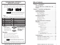
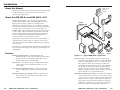
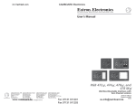
User’s Guide
RGB 203 Rxi
RGB 203 Rxi VTG
www.extron.com
Extron Electronics, USA
Extron Electronics, Europe
Extron Electronics, Asia
Extron Electronics, Japan
1230 South Lewis Street
Anaheim, CA 92805
USA
714.491.1500
Fax 714.491.1517
Beeldschermweg 6C
3821 AH Amersfoort
The Netherlands
+31.33.453.4040
Fax +31.33.453.4050
135 Joo Seng Road, #04-01
PM Industrial Building
Singapore 368363
+65.6383.4400
Fax +65.6383.4664
Daisan DMJ Building 6F
3-9-1 Kudan Minami
Chiyoda-ku, Tokyo 102-0074 Japan
+81.3.3511.7655
Fax +81.3.3511.7656
© 2003 Extron Electronics. All rights reserved.
Universal Video Interface with Audio
Universal Video Interface with Audio and mini VTG
68-655-01 Rev. A
Printed in the USA
01 03
Precautions
Safety Instructions • English
This symbol is intended to alert the user of important
operating and maintenance (servicing) instructions
in the literature provided with the equipment.
This symbol is intended to alert the user of the
presence of uninsulated dangerous voltage within
the product's enclosure that may present a risk of
electric shock.
Caution
Read Instructions • Read and understand all safety and operating
instructions before using the equipment.
Retain Instructions • The safety instructions should be kept for future
reference.
Follow Warnings • Follow all warnings and instructions marked on the
equipment or in the user information.
Avoid Attachments • Do not use tools or attachments that are not
recommended by the equipment manufacturer because they may be
hazardous.
Consignes de Sécurité • Français
Ce symbole sert à avertir l’utilisateur que la
documentation fournie avec le matériel contient des
instructions importantes concernant l’exploitation
et la maintenance (réparation).
Ce symbole sert à avertir l’utilisateur de la présence
dans le boîtier de l’appareil de tensions dangereuses
non isolées posant des risques d’électrocution.
Attention
Lire les instructions• Prendre connaissance de toutes les consignes de
sécurité et d’exploitation avant d’utiliser le matériel.
Conserver les instructions• Ranger les consignes de sécurité afin de
pouvoir les consulter à l’avenir.
Respecter les avertissements • Observer tous les avertissements et
consignes marqués sur le matériel ou présentés dans la documentation
utilisateur.
Eviter les pièces de fixation • Ne pas utiliser de pièces de fixation ni
d’outils non recommandés par le fabricant du matériel car cela
risquerait de poser certains dangers.
Sicherheitsanleitungen • Deutsch
Dieses Symbol soll dem Benutzer in der im
Lieferumfang enthaltenen Dokumentation
besonders wichtige Hinweise zur Bedienung und
Wartung (Instandhaltung) geben.
Dieses Symbol soll den Benutzer darauf aufmerksam
machen, daß im Inneren des Gehäuses dieses
Produktes gefährliche Spannungen, die nicht isoliert
sind und die einen elektrischen Schock verursachen
können, herrschen.
Achtung
Lesen der Anleitungen • Bevor Sie das Gerät zum ersten Mal verwenden,
sollten Sie alle Sicherheits-und Bedienungsanleitungen genau
durchlesen und verstehen.
Aufbewahren der Anleitungen • Die Hinweise zur elektrischen Sicherheit
des Produktes sollten Sie aufbewahren, damit Sie im Bedarfsfall darauf
zurückgreifen können.
Befolgen der Warnhinweise • Befolgen Sie alle Warnhinweise und
Anleitungen auf dem Gerät oder in der Benutzerdokumentation.
Keine Zusatzgeräte • Verwenden Sie keine Werkzeuge oder Zusatzgeräte,
die nicht ausdrücklich vom Hersteller empfohlen wurden, da diese eine
Gefahrenquelle darstellen können.
Instrucciones de seguridad • Español
Este símbolo se utiliza para advertir al usuario sobre
instrucciones importantes de operación y
mantenimiento (o cambio de partes) que se desean
destacar en el contenido de la documentación
suministrada con los equipos.
Este símbolo se utiliza para advertir al usuario sobre
la presencia de elementos con voltaje peligroso sin
protección aislante, que puedan encontrarse dentro
de la caja o alojamiento del producto, y que puedan
representar riesgo de electrocución.
Precaucion
Leer las instrucciones • Leer y analizar todas las instrucciones de
operación y seguridad, antes de usar el equipo.
Conservar las instrucciones • Conservar las instrucciones de seguridad
para futura consulta.
Obedecer las advertencias • Todas las advertencias e instrucciones
marcadas en el equipo o en la documentación del usuario, deben ser
obedecidas.
Evitar el uso de accesorios • No usar herramientas o accesorios que no
sean especificamente recomendados por el fabricante, ya que podrian
implicar riesgos.
FCC Class A Notice
Warning
Power sources • This equipment should be operated only from the power source
indicated on the product. This equipment is intended to be used with a main
power system with a grounded (neutral) conductor. The third (grounding) pin is
a safety feature, do not attempt to bypass or disable it.
Power disconnection • To remove power from the equipment safely, remove all
power cords from the rear of the equipment, or the desktop power module (if
detachable), or from the power source receptacle (wall plug).
Power cord protection • Power cords should be routed so that they are not likely to
be stepped on or pinched by items placed upon or against them.
Servicing • Refer all servicing to qualified service personnel. There are no userserviceable parts inside. To prevent the risk of shock, do not attempt to service
this equipment yourself because opening or removing covers may expose you to
dangerous voltage or other hazards.
Slots and openings • If the equipment has slots or holes in the enclosure, these are
provided to prevent overheating of sensitive components inside. These openings
must never be blocked by other objects.
Lithium battery • There is a danger of explosion if battery is incorrectly replaced.
Replace it only with the same or equivalent type recommended by the
manufacturer. Dispose of used batteries according to the manufacturer's
instructions.
Note: This equipment has been tested and found to comply with the limits for a
Class A digital device, pursuant to part 15 of the FCC Rules. These limits are designed
to provide reasonable protection against harmful interference when the equipment is
operated in a commercial environment. This equipment generates, uses and can
radiate radio frequency energy and, if not installed and used in accordance with the
instruction manual, may cause harmful interference to radio communications.
Operation of this equipment in a residential area is likely to cause harmful
interference, in which case the user will be required to correct the interference at his
own expense.
Note: This unit was tested with shielded cables on the peripheral devices. Shielded
cables must be used with the unit to ensure compliance.
Avertissement
Alimentations• Ne faire fonctionner ce matériel qu’avec la source d’alimentation
indiquée sur l’appareil. Ce matériel doit être utilisé avec une alimentation
principale comportant un fil de terre (neutre). Le troisième contact (de mise à la
terre) constitue un dispositif de sécurité : n’essayez pas de la contourner ni de la
désactiver.
Déconnexion de l’alimentation• Pour mettre le matériel hors tension sans danger,
déconnectez tous les cordons d’alimentation de l’arrière de l’appareil ou du
module d’alimentation de bureau (s’il est amovible) ou encore de la prise secteur.
Protection du cordon d’alimentation • Acheminer les cordons d’alimentation de
manière à ce que personne ne risque de marcher dessus et à ce qu’ils ne soient
pas écrasés ou pincés par des objets.
Réparation-maintenance • Faire exécuter toutes les interventions de réparationmaintenance par un technicien qualifié. Aucun des éléments internes ne peut être
réparé par l’utilisateur. Afin d’éviter tout danger d’électrocution, l’utilisateur ne
doit pas essayer de procéder lui-même à ces opérations car l’ouverture ou le
retrait des couvercles risquent de l’exposer à de hautes tensions et autres dangers.
Fentes et orifices • Si le boîtier de l’appareil comporte des fentes ou des orifices,
ceux-ci servent à empêcher les composants internes sensibles de surchauffer. Ces
ouvertures ne doivent jamais être bloquées par des objets.
Lithium Batterie • Il a danger d'explosion s'll y a remplacment incorrect de la
batterie. Remplacer uniquement avec une batterie du meme type ou d'un ype
equivalent recommande par le constructeur. Mettre au reut les batteries usagees
conformement aux instructions du fabricant.
Vorsicht
Stromquellen • Dieses Gerät sollte nur über die auf dem Produkt angegebene
Stromquelle betrieben werden. Dieses Gerät wurde für eine Verwendung mit
einer Hauptstromleitung mit einem geerdeten (neutralen) Leiter konzipiert. Der
dritte Kontakt ist für einen Erdanschluß, und stellt eine Sicherheitsfunktion dar.
Diese sollte nicht umgangen oder außer Betrieb gesetzt werden.
Stromunterbrechung • Um das Gerät auf sichere Weise vom Netz zu trennen,
sollten Sie alle Netzkabel aus der Rückseite des Gerätes, aus der externen
Stomversorgung (falls dies möglich ist) oder aus der Wandsteckdose ziehen.
Schutz des Netzkabels • Netzkabel sollten stets so verlegt werden, daß sie nicht
im Weg liegen und niemand darauf treten kann oder Objekte darauf- oder
unmittelbar dagegengestellt werden können.
Wartung • Alle Wartungsmaßnahmen sollten nur von qualifiziertem
Servicepersonal durchgeführt werden. Die internen Komponenten des Gerätes
sind wartungsfrei. Zur Vermeidung eines elektrischen Schocks versuchen Sie in
keinem Fall, dieses Gerät selbst öffnen, da beim Entfernen der Abdeckungen die
Gefahr eines elektrischen Schlags und/oder andere Gefahren bestehen.
Schlitze und Öffnungen • Wenn das Gerät Schlitze oder Löcher im Gehäuse
aufweist, dienen diese zur Vermeidung einer Überhitzung der empfindlichen
Teile im Inneren. Diese Öffnungen dürfen niemals von anderen Objekten
blockiert werden.
Litium-Batterie • Explosionsgefahr, falls die Batterie nicht richtig ersetzt wird.
Ersetzen Sie verbrauchte Batterien nur durch den gleichen oder einen
vergleichbaren Batterietyp, der auch vom Hersteller empfohlen wird. Entsorgen
Sie verbrauchte Batterien bitte gemäß den Herstelleranweisungen.
Advertencia
Alimentación eléctrica • Este equipo debe conectarse únicamente a la fuente/tipo
de alimentación eléctrica indicada en el mismo. La alimentación eléctrica de este
equipo debe provenir de un sistema de distribución general con conductor
neutro a tierra. La tercera pata (puesta a tierra) es una medida de seguridad, no
puentearia ni eliminaria.
Desconexión de alimentación eléctrica • Para desconectar con seguridad la
acometida de alimentación eléctrica al equipo, desenchufar todos los cables de
alimentación en el panel trasero del equipo, o desenchufar el módulo de
alimentación (si fuera independiente), o desenchufar el cable del receptáculo de
la pared.
Protección del cables de alimentación • Los cables de alimentación eléctrica se
deben instalar en lugares donde no sean pisados ni apretados por objetos que se
puedan apoyar sobre ellos.
Reparaciones/mantenimiento • Solicitar siempre los servicios técnicos de personal
calificado. En el interior no hay partes a las que el usuario deba acceder. Para
evitar riesgo de electrocución, no intentar personalmente la reparación/
mantenimiento de este equipo, ya que al abrir o extraer las tapas puede quedar
expuesto a voltajes peligrosos u otros riesgos.
Ranuras y aberturas • Si el equipo posee ranuras o orificios en su caja/alojamiento,
es para evitar el sobrecalientamiento de componentes internos sensibles. Estas
aberturas nunca se deben obstruir con otros objetos.
Batería de litio • Existe riesgo de explosión si esta batería se coloca en la posición
incorrecta. Cambiar esta batería únicamente con el mismo tipo (o su equivalente)
recomendado por el fabricante. Desachar las baterías usadas siguiendo las
instrucciones del fabricante.
Extron’s Warranty
Extron Electronics warrants this product against defects in materials and
workmanship for a period of three years from the date of purchase. In the event of
malfunction during the warranty period attributable directly to faulty workmanship
and/or materials, Extron Electronics will, at its option, repair or replace said products
or components, to whatever extent it shall deem necessary to restore said product to
proper operating condition, provided that it is returned within the warranty period,
with proof of purchase and description of malfunction to:
USA, Canada, South America,
and Central America:
Extron Electronics
1230 South Lewis Street
Anaheim, CA 92805, USA
Asia:
Extron Electronics, Asia
135 Joo Seng Road, #04-01
PM Industrial Bldg.
Singapore 368363
Europe, Africa, and the Middle East:
Extron Electronics, Europe
Beeldschermweg 6C
3821 AH Amersfoort
The Netherlands
Japan:
Extron Electronics, Japan
Daisan DMJ Bldg. 6F,
3-9-1 Kudan Minami
Chiyoda-ku, Tokyo 102-0074
Japan
This Limited Warranty does not apply if the fault has been caused by misuse,
improper handling care, electrical or mechanical abuse, abnormal operating conditions
or non-Extron authorized modification to the product.
If it has been determined that the product is defective, please call Extron and ask for
an Applications Engineer at (714) 491-1500 (USA), 31.33.453.4040 (Europe),
65.6383.4400 (Asia), or 81.3.3511.7655 (Japan) to receive an RA# (Return Authorization
number). This will begin the repair process as quickly as possible.
Units must be returned insured, with shipping charges prepaid. If not insured, you
assume the risk of loss or damage during shipment. Returned units must include the
serial number and a description of the problem, as well as the name of the person to
contact in case there are any questions.
Extron Electronics makes no further warranties either expressed or implied with
respect to the product and its quality, performance, merchantability, or fitness for any
particular use. In no event will Extron Electronics be liable for direct, indirect, or
consequential damages resulting from any defect in this product even if Extron
Electronics has been advised of such damage.
Please note that laws vary from state to state and country to country, and that some
provisions of this warranty may not apply to you.
Quick Start Guide — RGB 203 Rxi,,
RGB 203 Rxi VTG
Step 1
Turn the equipment off and disconnect the equipment power.
Step 2
For positive or negative output sync (rather than sync following the
input), to clamp sync timing to the back porch, or to disable the mini
VTG timeout (RGB 203 Rxi VTG only), open the interface and
configure the jumpers and/or DIP switches. See Internal Configuration,
beginning on page 2-3, for details.
Step 3
Rack, under-desk, or through-desk mount the interface as desired.
Rack — Use the optional 1U Rack Shelf, part #60-190-01.
Under-desk — Use the optional Under-Desk Mount Kit, part #70-077-01.
Thru-desk — Use the optional Thru-Desk Mount Kit, part #70-077-02.
Step 4
Video inputs — Connect an RGBHV, RGBS, RGsB or RsGsBs video
input to each 15-pin HD Input connector as desired.
Step 5
Audio inputs — Connect an unbalanced stereo audio source (such as a
computer or a CD player) to each 3.5 mm mini stereo Audio connector
for unbalanced audio input as desired. See the figure below to wire
the audio plug.
Tip (L)
Ring (R)
Sleeve ( )
Step 6
Monitor output — If desired, connect a local monitor or other device
to this 15-pin HD female connector.
Step 7
Video output — Connect an RGBHV, RGBS, or RGsB video display or
other device as shown below.
R
G
B
R
G
B
R
G
B
H
V
S
H
V
S
H
V
S
RGBHV
RGBS
RGsB
RGB 203 Rxi, RGB 203 Rxi VTG • Quick Start Guide
Quick Start Guide — RGB 203 Rxi,
RGB 203 Rxi VTG, cont’d
Table of Contents
Chapter 1 • Introduction .......................................................... 1-1
Step 8
Audio output — Connect an audio device to this 3.5 mm, 5-pole
captive screw connector for balanced or unbalanced audio output. See
below to properly wire the captive screw audio connector.
Chapter 2 • Installation and Operation ......................... 2-1
Balanced Output
Unbalanced Output
CAUTION
L or
Mono
Tip
Ring
Sleeve (s)
Tip
Ring
Tip
See caution
Sleeve(s)
Tip
See caution
Wiring the audio incorrectly can damage the audio
output circuits. Connect the sleeve(s) to ground
(GND). Connecting the sleeve(s) to a negative (-)
terminal will damage audio output circuits.
Step 9
Installation Overview .......................................................... 2-2
Internal Configuration ....................................................... 2-3
Sync polarity jumpers ............................................................ 2-4
Video clamping jumper ......................................................... 2-5
VTG timeout (RGB203 Rxi VTG only) .................................... 2-5
Mounting the Interface ...................................................... 2-5
DIP switches — Configure the rear panel DIP switches as shown:
Switch
About this Manual ................................................................ 1-2
About the RGB 203 Rxi and RGB 203 Rxi VTG .......... 1-2
Features ...................................................................................... 1-2
Position
Switch
Up
DDSP, no sync processing
1
Down ADSP
Up
RGsB output
2
Down RGBHV or RGBS output
Up
Serration pulses
3
Down No serration pulses
Up
Narrow vertical sync pulse
4
Down Wide vertical sync pulse
Position
Up
5
Down
Up
6
Down
7
8
Monitor
input selection, ID bits 4, 11 grounded
Monitor is tied to in #1, ID bits unterminated
Mono on left channel
Stereo audio
Up
Autoswitches to highest in# with sync present
Down Autoswitching off
Up
LCD backlight off
Down LCD backlight on
Pin RS-232
Step 10
5
Remote connector —
Connect an RS-232
device to this connector
for remote control. See
chapter 3, Remote Control.
1
9
6
Female
1
5
6
Operation
9
Male
1
2
3
4
5
6
7
8
9
—
TX
RX
—
Gnd
—
—
—
—
Contact
closure
In#1
—
—
In#2
Gnd
In#3
—
—
—
Function
Input #1
Transmit data (-)
Receive data (+)
Input #2
Signal ground
Input #3
—
—
—
Level/boost — Alters the picture’s brightness.
Peak — Affects the picture’s sharpness.
— Move the image up and down on the screen.
— Move the image right and left on the screen.
Input selection — Selects among inputs 1, 2, and 3.
The interface handles audio on inputs 1 and 2 only.
When you select input 3, the audio output is muted.
Tabletop placement ............................................................... 2-5
Under-desk mounting ........................................................... 2-5
Through-desk mounting ....................................................... 2-7
Rack mounting ....................................................................... 2-8
Rear Panel Connections and Switches ....................... 2-9
Operation ................................................................................. 2-13
Front panel controls and indicators ................................... 2-14
Level and peaking controls ................................................ 2-14
Centering controls .............................................................. 2-15
Centering memory .................................................. 2-15
LCD display .......................................................................... 2-16
LCD screen backlight ............................................... 2-16
Scan rate indication ................................................. 2-16
Centering indications .............................................. 2-16
VTG indications ........................................................ 2-17
Input selection .................................................................... 2-17
VTG controls (RGB 203 Rxi only) ........................................ 2-18
Operating the VTG .................................................. 2-19
Executive mode (front panel security lockout) ................. 2-19
Troubleshooting ................................................................... 2-19
If the image does not appear or there is no sound .......... 2-19
If the image is not displayed correctly ............................... 2-20
If the image does not respond to controls ........................ 2-21
If the image is not correctly centered ................................ 2-21
If autoswitching does not work ......................................... 2-21
203/VTG — Selects the output signal’s source (input 1, 2, or 3 or VTG).
VTG rotary switch — Selects display resolution and video test pattern.
RGB 203 Rxi, RGB 203 Rxi VTG • Quick Start Guide
RGB 203 Rxi, RGB 203 Rxi VTG • Table of Contents
i
Table of Contents, cont’d
Chapter 3 • Remote Control .................................................. 3-1
Simple Instruction Set Control ....................................... 3-2
Host-to-interface communications ....................................... 3-2
Interface-initiated messages ................................................. 3-2
Error responses ...................................................................... 3-2
Timeout .................................................................................. 3-2
Using the command/response table ..................................... 3-2
Symbol definitions ................................................................. 3-4
Command/response table for SIS commands ....................... 3-5
Control Software for Windows ...................................... 3-6
Installing the software .......................................................... 3-6
Command/response table for SIS commands ....................... 3-6
Using the software ................................................................ 3-6
Using the help system ........................................................... 3-6
Contact Closure Remote Control ................................... 3-7
Appendix • Reference Information ................................. A-1
Specifications ......................................................................... A-2
Included Parts ......................................................................... A-5
Optional Accessories ........................................................... A-5
Cables ......................................................................................... A-5
RGB 203 Rxi, RGB 203 Rxi VTG
1
Chapter One
Introduction
About this Manual
About the RGB 203 Rxi and RGB 203 Rxi VTG
Features
68-655-01 Rev. A
Printed in the USA
01 03
All trademarks mentioned in this manual are the properties of their respective owners.
ii
RGB 203 Rxi, RGB 203 Rxi VTG • Table of Contents
Introduction, cont’d
Introduction
About this Manual
This manual contains information about the Extron RGB 203 Rxi
and RGB 203 Rxi VTG universal interfaces and on how to
operate and configure them.
Hi
Hi
Carol
RS-232 Control
System or
Computer
Carol
About the RGB 203 Rxi and RGB 203 Rxi VTG
Extron
RGB 203 Rxi
Audio
Interface
TE
MO
RE
B
G
R
R
S
T3
PU
IN
T1
PU
IN
AUD
DDSP
SOG
SERR
V SYNC WIDTH
MONITOR FOLLOWS
MONO AUDIO LEFT
AUTO SWITCH
NO BACK LIGHT
The RGB 203 Rxi (figure 1-1) is an analog computer-video
interface with 300 MHz (-3dB) video bandwidth, Advanced
Digital Sync Processing™ (ADSP™), and Digital Sync
Validation Processing™ (DSVP™). It accepts three computervideo and two unbalanced computer stereo audio inputs (Input
3 is video only). It also features a local monitor output, an
RGBHV, RGBS or RGsB output and a balanced, line level stereo
or mono audio output. The interface features horizontal and
vertical centering and level boost and peaking. The RGB 203
Rxi VTG is identical to the RGB 203 Rxi except that it also
contains a built-in video test generator (VTG).
O
ON
L/M
S
UT
TP
OU
V
H
IO
OR
NIT
MO
0.2A
-240
100
AUD
IO
T2
PU
IN
0 Hz
50/6
Front panel controls, remote contact closure, autoswitching, or
an RS-232 remote control system or computer can be used to
select among inputs and to shift the output image horizontally
and vertically.
Projector
The interfaces are rack-mountable and furniture-mountable and
have an internal switching power supply for worldwide power
compatibility.
Features
Flexible mounting options — The RGB 203 Rxi and
RGB 203 Rxi VTG can be rack mounted, mounted under a
desk or podium, or mounted through a desk or other
furniture with optional mounting kits.
Stereo audio — The interface processes unbalanced PC stereo
audio inputs as a line level, balanced stereo or mono
audio output.
Level (boost) and peaking controls — Separate front panel
controls compensate for signal losses from long cable
runs.
Horizontal and vertical centering controls — Separate front
panel controls allow separate horizontal and vertical
centering adjustments.
1-2
RGB 203 Rxi, RGB 203 Rxi VTG • Introduction
PC
Laptop
Local Monitor
Document
Camera
Figure 1-1 — Typical RGB 203 Rxi application
Sync processing — Using regular sync processing to allow
centering control (H-shift or V-shift) can create problems
with some digital display devices as a result of the sync
delay. Extron’s ADSP option maintains a stable sync
signal while allowing centering control. These interfaces
also provide another option, DDSP™ (Digital Display
Sync Processing™), to ensure proper displays without
altering sync pulse timing or width. The sync processing
type is selected via a rear panel DIP switch.
Digital Sync Validation Processing — In critical environments
or unmanned, remote locations, it is vital to know which
sources are active. Extron’s exclusive DSVP confirms that
input sources are active by scanning all sync inputs for
active signals. DSVP provides instantaneous frequency
feedback for composite sync or separate horizontal and
vertical sync signals via the interface’s Remote port.
RGB 203 Rxi, RGB 203 Rxi VTG • Introduction
1-3
Introduction, cont’d
Thirty memory presets — Thirty spaces are reserved in the
interface’s memory for storing user-defined combinations
of horizontal and vertical position settings based upon
input signal scan rates. The interface automatically
recalls the position settings when it detects an input
signal with a matching scan rate.
LCD scan rate indicator — This backlit liquid crystal display
(LCD) indicates the horizontal and vertical sync rates,
and the minimum and maximum centering limits. A DIP
switch is provided for turning off the backlight.
RGBHV, RGBS, or RGsB outputs — Select the output format
via cabling setup and rear panel DIP switch.
Serration pulse switch — This DIP switch-selectable feature
adds or strips the serration pulses from the output signal
to make it compatible with digital display devices. Use
the serration pulse switch if flagging or bending occurs at
the top of the video display.
Sync polarity adjustment — Horizontal and vertical sync
output can either follow input sync polarity, or outgoing
sync can be forced to positive or negative via an internal
jumper.
Vertical sync pulse width adjustment — Vertical sync pulse
width can be adjusted via a rear panel DIP switch.
Remote control input selection — Connect a remote contact
closure keypad, an RS-232 control system, or a computer
to the rear panel Remote port to remotely control the
interface.
Executive mode — Locks out front panel control of horizontal
and vertical shift and input selection (with the exception
of VTG mode).
Vented metal enclosure — Vents in the enclosure keep the
interface cool and ready for use 24 hours a day, 7 days per
week.
Automatic sync stripping — Sync signals are automatically
stripped from the red, green, and blue video input
signals. The interfaces normally output sync
simultaneously as separate horizontal and vertical sync
and as composite sync, but sync on green (SOG) can be
selected via a rear panel DIP switch.
Video test generator (RGB 203 Rxi VTG only) — The VTG
version of the RGB 203 Rxi includes a 4-resolution (VGA,
SVGA, XGA, and SGI), 4-pattern video test generator to
simplify system setup and testing.
1-4
RGB 203 Rxi, RGB 203 Rxi VTG • Introduction
RGB 203 Rxi, RGB 203 Rxi VTG
2
Chapter Two
Installation and Operation
Installation Overview
Internal Configuration
Mounting the Interface
Rear Panel Connections and Switches
Operation
Troubleshooting
Installation and
Operation,
cont’d
Installation
and
Operation
Installation Overview
This is an overview of the installation process. You will find
detailed installation and operation instructions in this chapter.
To install and set up the RGB 203 Rxi and RGB 203 Rxi VTG
interfaces, follow these basic steps:
1
Turn all of the equipment (computers, remote controls,
interface, projector/monitor, local monitor, and speakers
or other audio device) off. Disconnect the power cords
from the power source.
Sync polarity, video clamp, and VTG timer configuration
require opening the interface’s case and should be done
before the interface is mounted.
2
10
For the RGB 203 Rxi VTG, set up and test the VTG. See
Operating the VTG in this chapter.
Internal Configuration
The interface is factory configured to output RGBHV or RGBS
video whose sync follows the input and that is clamped to the
back porch. The interface can be configured to output positive
or negative sync or to clamp on the sync tip. The timeout
functions of VTG models can be turned off. All of these
reconfigurations require opening the interface’s case.
1.
Remove the three screws on each side and the two screws
on top of the cover (figure 2-1).
Slide cover back slightly,
then lift straight up.
If you want the interface to always output positive sync or
negative sync, rather than following the input sync
polarity, open the interface and shift internal jumpers as
necessary. See Internal Configuration and its subsection,
Sync polarity jumpers, in this chapter.
LE
VE
L
PE
AK
BO
OS
T
3
4
5
2-2
If you want to clamp the sync timing of the video output
to the sync tip rather than the back porch, open the
interface and shift an internal jumper. See Internal
Configuration and its subsection, Video clamping jumper, in
this chapter.
RGB 203 Rxi VTG only, if you want the built-in mini VTG
to continuously output the selected test pattern rather
than time out after 5 minutes, remove an internal jumper.
See Internal Configuration and its subsection, VTG timeout
(RGB 203 Rxi VTG only), in this chapter.
Install the rubber feet for tabletop use, or install the
appropriate brackets and furniture or rack mount the
interface. See Mounting the Interface in this chapter.
6
Connect the inputs (computers), output (display, local
monitor, and audio), and remote control. See Rear Panel
Connections and Switches in this chapter.
7
Set the rear panel DIP switches. See Rear Panel Connections
and Switches in this chapter as a guide.
8
Connect power cords and turn on the devices: output
devices (projector, monitors, speakers), remote control
device, interface, and source computers.
9
Adjust horizontal and vertical centering, and adjust the
level and peaking to obtain the best picture.
RGB 203 Rxi, RGB 203 Rxi VTG • Installation and Operation
CO
NT
RO
L
CE
NT
ER
ING
SX
GA
MINI
XG
A
Remove (6)
Screws
VT
G
VG
A
20
3
SV
GA
VT
G
RG
B2
03
xi
VT
G
WITH
AD
SP TM
INPU
T
1
2
3
Figure 2-1 — Opening the interface
2.
Lift the cover off.
3.
Configure the interface as desired. See Sync polarity
jumpers, Video clamping jumper, and VTG timeout
(RGB 203 Rxi VTG only) in this chapter. Figure 2-2 shows
the location of all of the user-serviceable components.
4.
Replace the cover and reinstall the screws.
RGB 203 Rxi, RGB 203 Rxi VTG • Installation and Operation
2-3
Installation and Operation, cont’d
Video clamping jumper
The interface is factory configured to clamp the sync timing to
the back porch. To clamp the sync timing to the tip of the sync
pulse, reconfigure the jumper as follows:
J7 H Sync
J6 V Sync
J20 Enable
Sync
J11
1
2
3
1.
Locate J11 on the printed circuit board.
2.
For sync timing clamped to the back porch, ensure that a
jumper is in place from pin 1 to pin 2.
3.
For sync timing clamped to the sync tip, ensure that a
jumper is in place from pin 2 to pin 3.
1
1
J28
VTG timeout (RGB 203 Rxi VTG only)
J23
RS-232
Connector
J27
Figure 2-2 — Jumper locations
Sync polarity jumpers
The interface is factory configured for the output sync to follow
the input sync. To force positive or negative sync, reconfigure
the jumper as follows:
1.
Locate jumper blocks J6, J7, and J20 on the printed circuit
board.
2.
For sync follow (output sync polarity identical to the
input sync), ensure that the jumper is removed from
jumper block J20.
3.
For positive or negative sync, ensure that a jumper is
installed in jumper block J20 and configure J6 and J7 as
follows:
a.
Vertical sync —
For positive sync, ensure that a jumper is installed in
jumper block J6.
For negative sync, ensure that the jumper is removed
from jumper block J6.
b.
Horizontal sync —
The built-in mini VTG is factory configured to output the
selected test pattern for 5 minutes. After the VTG times out, the
screen dims, but is still visible. The output remains dim until
you operate any of the front panel controls, resetting the timer
and outputting the VTG test pattern at full intensity.
Disable the VTG timer, causing the mini VTG to continuously
output the selected test pattern at full intensity until you turn
off the VTG portion of the interface as follows:
1.
Locate DIP switch J27 on the printed circuit board.
2.
Remove the jumper from J27.
Mounting the Interface
Select an installation option: tabletop placement, or under-desk,
through-desk or rack mounting. Follow the appropriate
procedure on the next three pages.
Tabletop placement
For tabletop or desktop placement only, install the self-adhesive
rubber feet/pads (provided) onto the four corners of the bottom
of the interface enclosure.
Under-desk mounting
1.
Secure the optional under-desk mounting brackets
(part #70-077-01) to the interface with the six machine
screws provided in the mounting kit (figure 2-3).
For positive sync, ensure that a jumper is installed in
jumper block J7.
For negative sync, ensure that the jumper is removed
from jumper block J7.
2-4
RGB 203 Rxi, RGB 203 Rxi VTG • Installation and Operation
RGB 203 Rxi, RGB 203 Rxi VTG • Installation and Operation
2-5
Installation and Operation, cont’d
Through-desk mounting
1.
If rubber feet were installed on the interface, remove them.
2.
Insert the machine screws provided in the optional
mounting kit (part #70-077-02) through the slots in the
through-desk mounting brackets, and loosely secure the
brackets to the interface (figure 2-4).
LE
VE
L
PE
AK
BO
OS
T
CO
NT
RO
L
CE
NT
ER
ING
SX
GA
XG
A
MINI
VT
G
VG
A
20
3
SV
GA
VT
G
VT
G
WITH
AD
SP TM
INPU
T
1
2
3
B
O
O
ST
N
VE
O
LE
C
L
TR
O
L
P
EA
K
C
EN
TE
R
A
G
G
IN
X
S
X
G
S
A
V
G
Figure 2-3 — Under-desk mounting
A
V
3
TG
20
IV
Figure 2-4 — Through-desk mounting
3.
Hold the interface with attached brackets against the
underside of the desk/table. With a soft pencil mark the
location of holes for screws on the desk. Mark the
opening, approximately 1.8” x 8.9” ( 4.6 cm x 22.6 cm).
4.
Cut out the material from the installation area with a
jigsaw. Check the opening size by inserting the interface
part way through the hole. If needed, use a saw, file or
sandpaper to enlarge the hole. Smooth the edges of the
hole with sandpaper.
Slide the interface slightly forward or back, then tighten all
four screws to fasten it in place.
RGB 203 Rxi, RGB 203 Rxi VTG • Installation and Operation
IN
A
2-6
M
6.
TM
Align the installed screws with the slots in the mounting
brackets, and place the interface against the surface, with
the screws through the bracket slots.
SP
5.
D
Insert the four wood screws into the pilot holes. Fasten
each screw into the installation surface until just less than
1/4” of the screw protrudes.
A
4.
H
Drill 1/4” (6.4 mm) deep, 3/32” (2 mm) diameter pilot
holes in the table or desk at the marked screw locations
from the underside/inside (concealed side) of the
furniture, where the interface will be located.
IT
3.
G
G
1
W
Hold the interface with attached brackets against the
underside of the desk or other furniture. Mark the
location of holes for screws on the desk.
V
T
T
G
2
PU
T
IN
V
3
2.
RGB 203 Rxi, RGB 203 Rxi VTG • Installation and Operation
2-7
Installation and Operation, cont’d
5.
Drill 1/4” (6.4 mm) deep, 3/32” (2 mm) diameter pilot
holes in the desk or table at the marked screw locations.
The holes should be drilled from the underside or inside
(concealed side) of the furniture, where the interface will
be located.
6.
Secure the interface to the desk with the provided wood
screws.
7.
To adjust the height of the interface within the desk, slide
the interface up or down to the desired position, then
tighten the screws that attach the brackets to the interface.
Use 2 mounting holes on
opposite corners.
Rack mounting
If feet were installed on the bottom of the interface,
remove them.
2.
Place the interface on one half of the 1U (one unit high,
19” wide) optional rack shelf (part #60-190-01). Align the
front of the interface with the front of the shelf, and align
the threaded holes on the bottom of the interface with the
holes in the rack shelf (figure 2-5).
3.
Secure the interface to the rack shelf with the two
provided 4-40 x 3/16” machine screws. Insert the screws
from the underside of the shelf and securely fasten them
through diagonally opposite corners as shown in
figure 2-5.
False Front panel
uses 2 front holes
LE
4.
5.
Fasten the false front panel (provided with the rack shelf)
to the unoccupied side of the rack (figure 2-5), or install a
second half-rack-width device in that side by repeating
steps 1 through 3.
VE
L
PE
BO
OS
AK
CE
T
CO
NT
RO
NT
ER
ING
L
SX
GA
XG
A
MINI
VT
G
VG
A
20
3
SV
GA
RG
B
20
3x
VT
G
(2) 4-40 x 3/16" Screws
iV
TG
WITH
INPU
AD
SP TM
T
1
2
3
Figure 2-5 — Rack mounting
Rear Panel Connections and Switches
Secure the rack shelf to the rack using four 10-32 x ¾” bolts.
Insert the bolts through #10 beveled washers, then through
the holes in the rack ears.
Figure 2-6 shows the rear panel of the RGB 203 Rxi. The
features described in this section apply to both models.
1
100-240
0.2A
2
1
7
INPUT 3
INPUT 1
R
G
B
AUDIO
H
V
S
AUDIO
50/60 Hz
8
INPUT 2
1
REMOTE
DDSP
SOG
SERR
V SYNC WIDTH
MONITOR FOLLOWS
MONO AUDIO LEFT
AUTO SWITCH
NO BACK LIGHT
1.
OUTPUTS
MONITOR
2
3
6
L/MONO
4
R
5
Figure 2-6 — RGB 203 Rxi rear panel features
1
2-8
RGB 203 Rxi, RGB 203 Rxi VTG • Installation and Operation
Inputs 1, 2, and 3 — Connect the analog computer-video
sources to these 15-pin HD female connectors.
RGB 203 Rxi, RGB 203 Rxi VTG • Installation and Operation
2-9
Installation and Operation, cont’d
Most laptop or notebook computers have an external
video port, but they require special commands to output
the video to that connector. Also, a laptop’s screen shuts
off once that port is activated. See the computer’s user’s
guide for details, or contact Extron for a list of laptop
keyboard commands.
Connect the sleeve(s) to ground (GND).
Connecting the sleeve(s) to a negative (-) terminal
will damage audio output circuits.
Tip
See caution
Sleeve(s)
Tip
See caution
Audio inputs 1 and 2 — Connect the unbalanced stereo audio
sources (such as the computers or a CD player) to these 3.5 mm
mini stereo jacks for unbalanced audio input. Figure 2-7 shows
how to wire the audio jack.
Tip (L)
Ring (R)
Wiring the audio incorrectly can damage the audio
output circuits.
Tip
Ring
Sleeve (s)
Tip
Ring
Unbalanced Output
L or
Mono
2
CAUTION
Balanced Output
Figure 2-8 — Wiring the audio output connector
6
DIP switches — This bank of DIP switches is used to configure
the interface. The switches control:
• DDSP or ADSP
Sleeve ( )
Figure 2-7 — Audio input connector wiring
3
4
R
H
• Serration pulses
• Vertical sync pulse width
BNC output connectors — Connect a coaxial cable between the
display (projector or monitor) and these rear panel BNC
G
B
connectors.
• Mono audio left
V
S
R
G
B
H
V
S
RGBS
R
G
B
H
V
S
RGsB
For RGBHV (separate H and V sync) output, connect the
cables to five BNCs.
For RGBS (composite sync), connect the cables to four
BNCs.
For RGsB (sync on green, SOG), connect the cables to three
BNCs. Also select the SOG option on the rear panel DIP
switch (see item 6 , Dip switches in this chapter.
Audio output connector — Connect an audio device, such as
powered speakers, to this 3.5 mm, 5-pole captive screw
connector for balanced or unbalanced audio output.
Figure 2-8 shows how to wire the captive screw audio
connector. The connector is included with the interface, but you
must obtain the cable. Insert the wires into the appropriate
openings in the captive screw connector. Tighten the
screws on top to fasten the wires.
2-10
• SOG (sync on green)
Monitor connector — If desired, connect a local monitor or
other device to this 15-pin HD female connector.
RGBHV
5
1 2 3 4 5 6 7 8
RGB 203 Rxi, RGB 203 Rxi VTG • Installation and Operation
• Monitor follows
• Auto-switching
• Backlight illumination.
The default for all DIP switches is Off (down).
1 — DDSP
DDSP disables all sync processing. This feature may be
necessary for digital display devices such as LCD, DLP
(digital light processor), and plasma displays. Use this
option if the image is not displayed properly after other
options, such as serration pulse and video termination
changes, have been tried.
On — The interface uses DDSP instead of ADSP.
DDSP does not process the sync signal.
DDSP disables the horizontal and vertical centering
controls.
Off — The interface performs sync processing operations,
such as centering, with ADSP.
RGB 203 Rxi, RGB 203 Rxi VTG • Installation and Operation
2-11
Installation and Operation, cont’d
8 — No LCD backlight — This switch controls illumination of
the LCD backlight.
2 — Sync on green
On — The interface outputs a composite sync signal on
top of the green video signal (SOG) via the G
output connector (RGsB).
Off — The interface outputs separate horizontal and
vertical sync (on the H and V connectors) and
composite sync (on the S connector) for RGBHV or
RGBS.
On — The LCD backlight is off, except for three seconds
at power-up.
Off — The LCD backlight is on while a signal is present at
the selected input.
7
3 — Serration pulses — Many LCD and DLP projectors and
plasma displays will not display properly if serration
pulses are present in the sync signal. Flagging or bending
at the top of the video image is a sign that the serration
pulses should be removed.
Remote connector — Connect an RS-232 device (control system
or PC computer) for remote switching between inputs and
remote centering control to this DB 9 female connector
(figure 2-9). Software for RS-232 control is included with the
interface. See chapter 3, Remote Control for details.
5
On — The interface outputs serration pulses in the vertical
sync interval.
Off — The interface does not output serration pulses.
9
6
Female
1
4 — Vertical sync pulse width — For some digital displays, if:
•
•
•
no picture appears
the picture cuts in and out
the picture is scrambled
On — Mono audio is output in the left channel only.
Off — Normal stereo output.
7 — Auto switch
On — The interface automatically switches to the highest
numbered input with sync present.
Off — Manual switch mode.
Auto switch works for RGBHV and RGBS video inputs
only. Auto switch does not work for RGsB video input.
2-12
RGB 203 Rxi, RGB 203 Rxi VTG • Installation and Operation
Pin
1
2
3
4
5
6
7
8
9
RS-232
—
TX
RX
—
Gnd
—
—
—
—
Contact closure
In#1
—
—
In#2
Gnd
In#3
—
—
—
Function
Input #1
Transmit data (-)
Receive data (+)
Input #2
Signal ground
Input #3
—
—
—
Figure 2-9 — Remote connector pin assignments
Connect a contact closure remote control device to this 9-pin D
female connector for remote switching between inputs.
8
6 — Monaural audio output
9
Male
On — The vertical sync pulse is narrow.
Off — The vertical sync pulse is wide.
On — The local monitor connector follows the input
selection and ID bits 4 and 11 are tied to ground.
Off — The local monitor output connector is locked to
input 1 and ID bits 4 and 11 are unterminated.
5
6
try adjusting the output vertical sync pulse width or
switching from ADSP to DDSP.
5 — Local monitor and ID bit termination — This switch
controls the input assigned to the local monitor output and
ID bit termination.
1
AC power connector — Connect a standard IEC AC power cord
here for power input (100VAC to 240VAC, 50/60 Hz) to the
internal, autoswitching power supply.
Operation
Connect power cords and turn on the display and audio output
devices (projectors, monitors, speakers), interface, and input
devices (computers). The system is ready for operation.
Select an input using the front panel toggle switch or the remote
control (keypad, system, or PC). The image should now appear
on screen and sound should be audible. If not, ensure that all
devices are plugged in and receiving power. Check the cabling
and switch settings, and make adjustments as needed. Select a
different input (or the VTG) to check for a picture and sound.
If problems persist, see Troubleshooting in this chapter. If the
troubleshooting tips do not help, call the Extron S3 Sales &
Technical Support Hotline.
RGB 203 Rxi, RGB 203 Rxi VTG • Installation and Operation
2-13
Installation and Operation, cont’d
this control while viewing the displayed image to obtain the
optimum picture sharpness.
Front panel controls and indicators
Figure 2-10 shows the front panel of the RGB 203 Rxi VTG. The
features described in this section apply to both models unless
otherwise noted in the description and by an asterisk (*) in the
callout number.
Centering controls
Many projectors store centering information in their own
memories based on signal frequency. When a projector displays
video from different input sources that have the same frequency,
one source’s images may not be centered. Using the interface’s
centering controls eliminates that problem.
VTG WITH ADSP TM
CENTERING
LEVEL
MINI VTG
PEAK
SXGA
VGA
203
SVGA
VTG
1
2
BOOST
XGA
CONTROL
3
3
Vertical centering ( ) — While viewing the displayed image,
rotate this control to move the image up or down on the screen.
During centering adjustment, the LCD displays V-SHIFT, and it
indicates the vertical shift minimum or maximum limit when
the centering limit has been reached. See the notes below item
4 .
4
Horizontal centering ( ) — While viewing the displayed
image, rotate this control to move the image to the right or left
on the screen. During centering adjustment, the LCD displays
H-SHIFT, and it indicates the horizontal shift minimum or
maximum limit when the centering limit has been reached.
INPUT
1
2
3
4
9*
8*
5
6
7
Figure 2-10 — RGB 203 Rxi VTG front panel
Level and peaking controls
1
LEVEL
Minimum:
0.50V p-p
BOOST
Level/boost control — The Level/boost control alters the video
output voltage to affect the brightness of the displayed
Unity:
image. Adjust the knob while viewing the displayed
0.70V p-p
image to set the level/boost that provides the best
Boost
Range
picture quality.
Maximum:
1.45V p-p
If the interface receives a typical (0.7 volts p-p) analog
computer video input, the output is as follows:
•
At the minimum level setting (the counterclockwise limit of
this control), the interface outputs video at 0.5 volts p-p.
•
Unity level is 0.7 volts p-p, the same as the input signal.
Set the control to just before the boost range (indicated by
the red line on the interface, the shaded area on the
illustration to the left) to output unity level video.
•
At the maximum level setting (the clockwise limit of this
control), the interface outputs video at 1.45 volts p-p.
Select a setting in the boost range (0.7 volts and above), to
compensate for the decrease in signal level that occurs
when the signal passes through long cables.
Set the boost at 100% (the maximum level) for cable
lengths over 500 feet for all computer signals of 15 kHz to
150 kHz.
2
2-14
Peaking (Peak) control — Peaking affects the sharpness of a
picture. Increased peaking can compensate for detail (mid- and
high-frequency) loss from low bandwidth system components
or capacitance in long cables. The minimum setting (at the
counterclockwise limit) provides no peaking. The maximum
setting (at the clockwise limit) provides 100% peaking. Adjust
RGB 203 Rxi, RGB 203 Rxi VTG • Installation and Operation
DDSP disables the interface’s vertical and horizontal
centering controls. If DIP switch 1 (DDSP) is set to On
and either centering control is rotated, the LCD displays
N/A DDSP ON.
To use the display’s centering controls rather than the
interface’s controls, set the DDSP DIP switch to On.
Executive mode (see Executive mode in this chapter)
disables the interface’s vertical and horizontal centering
controls. If executive mode is on and either centering
control is rotated, the LCD displays EXEC MODE ON.
The centering controls have no mechanical limits to
rotation. When the minimum or maximum limit of the
control is reached, LCD indicates the horizontal or
vertical shift limit has been reached and the picture stops
moving on the screen.
Centering memory
Turning the centering control knobs not only moves the images,
but it also stores the horizontal and vertical centering settings in
separate memories for each selected input. The interface recalls
the centering settings each time an input is selected. Centering
adjustments only need to be set once for an application because
the settings are saved even when the power is off.
RGB 203 Rxi, RGB 203 Rxi VTG • Installation and Operation
2-15
Installation and Operation, cont’d
VTG indications
LCD display
5
LCD display — The LCD serves two main functions: to display
the horizontal and vertical scanning rates of the input signal,
and to indicate the horizontal and vertical centering status and
limits. During VTG operation (RGB 203 Rxi VTG only), the
LCD displays the VTG format, resolution, and refresh rates.
LCD screen backlight
When the VTG function is active (RGB 203 Rxi VTG only), the
LCD displays the current format, resolution, and scan rate
settings.
Input selection
6
The LCD backlights for 15 seconds at power-up, and it remains
backlit as long as an input signal is present at the selected input.
To force the backlight to remain off at all times except at powerup, set DIP switch 8 (No Backlight) on the rear panel to On (up).
Scan rate indication
When the interface is powered on, the LCD lights for 15 seconds
while it determines whether an input sync signal is present. If
DIP switch 8 is set to On (up), the LCD lights for three seconds
only.
•
•
Down-switching
If the interface does not detect an input sync signal, the
LCD goes dark and displays NO SIGNAL until the
interface receives an active sync signal.
Start
If the interface detects an input sync signal, the LCD
displays the horizontal and vertical scan rates (sync
frequencies) in the following format:
The first line shows the horizontal rate in kilohertz, and
the second line shows the vertical rate in Hertz.
INPUT
1
1
2
2
3
3
1
1
2
2
3
3
1
1
2
2
3
3
1
1
2
Centering indications
3
While the vertical ( ) or horizontal ( ) centering (shift) controls
are being adjusted, the LCD displays H-SHIFT or V-SHIFT.
That message remains on the LCD (in place of the scan rates)
until the centering control has been inactive for 3 seconds.
When a centering control reaches its minimum or maximum
limit, the LCD displays MIN or MAX on the line below
H-SHIFT or V-SHIFT.
Start
2
3
Figure 2-11 — Switching among inputs
A remote RS-232 control system or computer or a contact
closure switch, connected via the rear panel Remote port, can
also switch among the inputs.
Executive mode (see Executive mode in this chapter)
disables the Input selection switch. If executive mode is
on and the Input selection switch is operated, the LCD
displays EXEC MODE ON.
Once the centering controls are no longer active, the centering
settings are saved, and the LCD displays the current scan rates.
If DIP switch 1 (DDSP) on the rear panel is set to On (up) and a
centering control is rotated, the LCD displays N/A DDSP ON,
and the image does not shift on screen.
The interface handles audio on inputs 1 and 2 only.
When you select input 3, the audio output is muted.
7
RGB 203 Rxi, RGB 203 Rxi VTG • Installation and Operation
Up-switching
INPUT
Hxxx.xxk
Vxxx.xHz
2-16
Input selection switch — The Input selection toggle switch
selects among inputs 1, 2, and 3 (figure 2-11). Each time you
move the switch down, the interface switches to the next lower
input (in the order that the inputs are listed on the front panel):
input 1 —> input 2, input 2 —> input 3, input 3 —> input 1.
Moving the switch up selects the next higher input (in the order
that the inputs are listed on the front panel). The switch returns
to the center position automatically.
Input LED — The lit LED indicates the selected input.
RGB 203 Rxi, RGB 203 Rxi VTG • Installation and Operation
2-17
Installation and Operation, cont’d
VTG controls (RGB 203 Rxi VTG only)
Operating the VTG
The RGB 203 Rxi VTG includes a limited video test generator.
The VTG creates and outputs standard test patterns at fixed
formats and resolutions so that a system can be set up and
tested even when an input computer is not available.
8*
Operate the VTG as follows:
1.
Set the front panel 203/VTG selection switch to VTG.
2.
Select an appropriate combination of output resolution
and test pattern using the 16-position rotary switch on the
front panel. Four different video test patterns are available
for each of the four resolutions. Select the test patterns by
rotating the switch within the appropriate resolution
quadrant. The LCD displays the selected VTG format, the
resolution, and then the scan rates.
203 (interface)/VTG selection switch — Use this switch to
select the output signal’s source:
203 — The interface outputs the selected input (from input 1, 2,
or 3) for display.
VTG — The interface outputs a test pattern generated by the
VTG for display.
When this switch is set to VTG, signals from input 1, 2,
and 3 are ignored; the interface’s internal VTG provides
a test pattern in place of the computer video input.
Input selection cannot be performed until the 203/VTG
selection switch is set to 203.
9*
VTG output resolution and pattern selection switch — Select a
combination of display resolution and video test pattern using
this 16-position rotary switch. Four different video test patterns
(figure 2-12) are available for each of the four resolutions offered
by the RGB 203 Rxi VTG’s built-in mini video test generator.
Crosshatch
H pattern
8 split-level grayscale
8 Color Bars
Figure 2-12 — Mini VTG test patterns
The table below shows the four available resolutions:
Switch
quadrant
Format
Resolution
(pixels x lines)
H. rate
(khz)
V. rate
(Hz)
1
VGA (VGA 3)
640 x 480
31.5
60
2
SVGA
800 x 600
37.9
60
3
XGA (VESA 3)
1024 x 768
48.4
60
4
SXGA (SGI)
1280 x 1024
64.0
60
Executive mode (front panel security lockout)
The executive mode limits the operation of the interface from
the front panel. When the interface is in executive mode, the
front panel Vertical centering ( ), Horizontal centering ( ), and
Input selection functions are disabled.
To toggle executive mode on or off, hold down the Input
selection switch for approximately five seconds. The LCD
displays EXEC MODE ON to indicate the mode change.
Release the switch. To toggle the executive mode off, hold
down the Input selection switch again until the LCD displays
EXEC MODE OFF.
Troubleshooting
Turn on the input devices (computer, audio device) and output
device(s) (projector, monitors, speakers). The image should
now appear on the screen, and sound should be audible.
If the image does not appear or there is no sound
2-18
RGB 203 Rxi, RGB 203 Rxi VTG • Installation and Operation
1.
Ensure that all devices are plugged in.
2.
Make sure that each device is receiving power. The
interface’s front panel LCD lights if the interface is
receiving power and an active sync signal.
RGB 203 Rxi, RGB 203 Rxi VTG • Installation and Operation
2-19
Installation and Operation, cont’d
3.
Check the cabling and the audio connector wiring and
grounding, and make adjustments as needed.
4.
For digital display devices (including LCD, DLP and
plasma devices), try turning DIP switch 1 (DDSP) On (up)
or Off (down) on the rear panel.
5.
To test the system setup and output, substitute a video test
generator for one of the computer inputs. Use the VTG
that is built into the RGB 203 Rxi VTG, or use a standalone VTG with the RGB 203 Rxi. To use a stand-alone
VTG, unplug the input and output devices’ and the
interface’s power cords, replace the video source with a
VTG, then reconnect power cords to restore AC power.
6.
If the interface does not respond to controls
1.
knob and knob — If you cannot adjust the horizontal
centering, DDSP may be in use. Ensure that DIP switch 1
(DDSP) on the rear panel is Off (down).
2.
knob, knob, and Input selection switch — If you
cannot shift between inputs or adjust the horizontal
centering from the front panel, but you can operate the
interface via a remote control, the interface may be in
executive mode. Toggle executive mode off, see Executive
mode (front panel security lockout) on page 2-19.
3.
(RGB 203 Rxi VTG only) knob, knob, and Input
selection switch — If you cannot shift between inputs or
adjust the horizontal centering on an RGB 203 Rxi VTG,
either on the front panel or via a remote control, the
interface may be in VTG mode. Set the front panel 203/
VTG toggle switch to the 203 position.
Call the Extron S3 Sales & Technical Support Hotline if
needed.
If the image is not displayed correctly
1.
If the image is not correctly centered
If the picture from a new source computer does not seem
correctly centered, the input position memory presets might
require resetting. Reset the input position memories as follows:
2.
If the picture bends or flags at the top of the screen, set the
serration pulse DIP switch (switch 3) to Off (down).
1.
Unplug the interface’s AC power cord.
3.
For a display device that experiences intermittent glitches,
try turning DDSP On (up) or Off (down) using DIP switch
1 on the rear panel.
2.
Hold down the input selector switch while you plug in the
interface’s AC power cord and wait approximately 5
seconds.
4.
If the picture “hangs off” the edges of the screen, adjust the
centering controls ( , ).
3.
Select the appropriate input and adjust the horizontal and
vertical centering.
5.
If the edges of the image seem to exceed their boundaries
or if thin lines and sharp edges look thick and fuzzy, try
changing the Level/Boost or Peak Control settings. If the
image is too bright, decrease the boost or peaking level.
6.
2-20
If the output image looks too green, the sync on green
(SOG) DIP switch (switch 2) may be set to On (up), and the
display device may not be configured to handle SOG
signals. Set the switch to Off (down).
If the image still does not display correctly, call the Extron
S3 Sales & Technical Support Hotline.
RGB 203 Rxi, RGB 203 Rxi VTG • Installation and Operation
If autoswitching does not work
Auto switch works for RGBHV and RGBS video inputs only.
Auto switch does not work for RGsB video input.
The selection of RGsB video output on rear panel DIP
switch 2 has no effect on autoswitching.
RGB 203 Rxi, RGB 203 Rxi VTG • Installation and Operation
2-21
Installation and Operation, cont’d
RGB 203 Rxi, RGB 203 Rxi VTG
3
Chapter Three
Remote Control
Simple Instruction Set Control
Command/Response Table for SIS Commands
Control Software for Windows
Contact Closure Remote Control
2-22
RGB 203 Rxi, RGB 203 Rxi VTG • Installation and Operation
Remote Control,
Remote
Controlcont’d
The interface’s rear panel Remote connector (Figure 3-1) can be
connected to the serial port output of a host device, such as a
computer or control system or to a remote contact closure
device. Remote communications with the switcher are via
Extron’s Simple Instruction Set, Extron’s Windows-based
control program, or pin-programmed in the case of a contact
closure device.
5
1
9
6
Female
1
5
6
9
Male
Pin
1
2
3
4
5
6
7
8
9
RS-232
—
TX
RX
—
Gnd
—
—
—
—
Contact closure
In#1
—
—
In#2
Gnd
In#3
—
—
—
Function
Input #1
Transmit data (-)
Receive data (+)
Input #2
Signal ground
Input #3
—
—
—
Figure 3-1 — Remote connector pin assignments
The RS-232 protocol of the rear panel Remote connector is 9600
baud, 1 stop bit, no parity, and no flow control.
Simple Instruction Set Control
Host-to-interface communications
SIS commands consist of one or more characters per field. No
special characters are required to begin or end a command
sequence. When a command is valid, the interface executes the
command and sends a response to the host device. All
responses from the interface to the host end with a carriage
return and a line feed (CR/LF = ), which signals the end of
the response character string. A string is one or more characters.
Interface-initiated messages
When a local event such as a front panel or contact closure
selection or adjustment takes place, the interface sends a
message to the host. No response is required from the host.
The interface-initiated messages are listed here (underlined).
status listing via the request information command (I/i). See
the command/response table in this chapter for details.
Chn
X2
The input number has been changed or, for the
RGB 203 Rxi VTG, the VTG has been turned on or off.
Error responses
When the interface receives a valid SIS command, it executes the
command and sends a response to the host device. If the
interface is unable to execute the command because the
command is invalid or it contains invalid parameters, it returns
an error response to the host.
The error response codes and their descriptions are as follows:
E01 – Invalid input number (the number is too large or small; occurs
when attempting to select VTG mode via RS-232)
E06 – Invalid input selection (occurs when selecting an input when
the RGB 203 Rxi VTG is set to VTG mode)
E10 – Invalid command
E13 – Invalid value (the number is out of range/too large)
Timeout
Pauses of 10 seconds or longer between command ASCII
characters result in a timeout. The command operation is
aborted with no other indication.
Using the command/response table
The command/response table is on page 3-5. Lower case letters
are allowed in the command field only as indicated. Symbols
are used throughout the table to represent variables in the
command/response fields. Command and response examples
are shown throughout the table. The ASCII to HEX conversion
table, on the next page, is for use with the command/response
table.
(C) Copyright 2002, Extron Electronics, RGB 203 Rxi, Vx.xx
The interface displays the copyright message when it first
powers on. Vx.xx is the firmware version number.
RECONFIG
When a change is made via a front panel control or another
operation occurs that must be written to a new memory block,
the interface sends the reconfiguration message. No response is
required from the RS-232 host, but the host may request a new
3-2
RGB 203 Rxi, RGB 203 Rxi VTG • Remote Control
RGB 203 Rxi, RGB 203 Rxi VTG • Remote Control
3-3
3-4
RGB 203 Rxi, RGB 203 Rxi VTG • Remote Control
/
Vph X2
Vph X2
Vph X2
Vph-005
I/i
N/n
n
Q/q
q
Request for part number
Example:
Query software version
Example:
RGB 203 Rxi, RGB 203 Rxi VTG • Remote Control
1.23
X3
60-509-01
X6
Software version 1.23 (example only).
60-509-01 = RGB 203 Rxi VTG.
Chn X5 •Hph X2 •Vph X2 •Hrt X4 •Vrt X4
Chn3•Hph+028•Vph-005•Hrt48.400•Vrt60.000
Input 3; horizontal shift value +28; vertical shift
value -5; horizontal rate 48.4 kHz; vertical rate
60 Hz.
Previous vertical shift value +1 (shift up).
Previous vertical shift value -1 (shift down).
Set vertical shift value to X2 .
Set horizontal shift value to -5.
Symbol definitions
Information request
Example
View, information, part number, and firmware requests
+/
-/
Increment vertical shift value
Decrement vertical shift value
X2
-5/
Vertical shift
Set vertical shift
Example:
= space
Previous horizontal shift value +1 (shift right).
Previous horizontal shift value -1 (shift left).
Set horizontal shift value to X2 .
Set horizontal shift value to +28.
Select input X1 .
Select input 3.
= CR/LF (carriage return/line feed) (0x0D 0A)
Hph X2
Hph X2
= Part number
+H
-H
X6
Increment horizontal shift value
Decrement horizontal shift value
1 - 3 (for input 1 through 3)
4 (VTG — RGB 203 Rxi VTG
only)
Hph X2
Hph+028
= Input selected
X2 H
28H
X5
Horizontal shift
Frequency in Hz or kHz
Set horizontal shift
Example:
= xxx.xx
Chn X1
Chn3
X4
!
= Controller firmware version (listed to two decimal
places, “x.xx”)
X1
X3
3!
-127 to +127
Select input
Example:
= Shift control range
Input selection
X2
Additional description
1, 2, or 3
(switcher to host)
= Input number
ASCII Command Response
X1
(host to switcher)
•
Command
Command/response table for SIS commands
Remote Control, cont’d
3-5
Remote Control, cont’d
1.
Double-click on the RGB 201 Control Pgm icon in the
Extron Electronics group or folder, or on the Rgb201.exe
icon in the C:\RGB201 directory. The Comm menu
appears on the screen.
2.
Click on the comm port that is connected to the interface’s
RS-232 port. The control software checks for the interface
at that port and reads its configuration.
ASCII to HEX Conversion Table
Space
The control program window (Figure 3-2) appears and
displays current settings.
Control Software for Windows
The included RGB 201/203/580 Control Program, graphical
control software for Windows, offers another way to control the
interface. The control software is compatible with Windows 3.1,
3.11, 95/98, and above.
Installing the software
The control program is contained on a 3.5-inch diskette, and it
can run from the floppy drive. However, it is more convenient
to run the program from the hard drive.
To install the software onto the hard drive, run
SETUP.EXE from the floppy disk, and follow the
instructions that appear on the screen. The
program requires approximately 1 MB
(megabyte) of hard disk space.
By default the installation creates a C:\RGB201 directory, and it
places two icons (RGB 201 Control Pgm and RGB 201 Help) into
a group or folder named “Extron Electronics”.
Using the software
To run the control program, follow these steps:
Figure 3-2 — RGB 203 Control program window
Using the help system
For information about program features, you can access the help
program in any of the following ways:
•
From the Extron Electronics program group, double-click
on the RGB 201 Help icon.
•
From within the Windows-based RGB 201/203/580
Control Program, click on the Help entry on the task bar.
•
From within the Windows-based switcher control
program, press the F1 key.
Contact Closure Remote Control
The rear panel Remote connector also provides a way to select
an input to the interface using a remote contact closure device.
Contact closure control uses pins on the Remote connector that
are not used by the RS-232 interface. The contact closure pin
assignments are shown in the table on page 3-2.
To select a different input number using a contact closure
device, momentarily short the pin for the desired input number
to logic ground (pin 5). To force one of the inputs to be always
selected, leave the short to logic ground in place. The short
overrides front panel input selections.
3-6
RGB 203 Rxi, RGB 203 Rxi VTG • Remote Control
Shorting the contact closure pin to override the front
panel selection will not work if the interface is in auto-
RGB 203 Rxi, RGB 203 Rxi VTG • Remote Control
3-7
Remote Control, cont’d
RGB 203 Rxi, RGB 203 Rxi VTG
A
Appendix
Reference Information
Specifications
Included Parts
Optional Accessories
Cables
3-8
RGB 203 Rxi, RGB 203 Rxi VTG • Remote Control
Reference Information,
cont’d
Reference
Information
Sync
Specifications
Video
Routing ..........................................
Gain ...............................................
Bandwidth ....................................
Rise time ........................................
3 x 1 router
0.5V to 1.45V p-p
300 MHz (-3dB)
1.5 ns
Video input
Number/signal type ...................
Connectors ....................................
Nominal level ...............................
Minimum/maximum levels ......
Impedance ....................................
Horizontal frequency ..................
Vertical frequency .......................
Return loss ....................................
Maximum DC offset ....................
3 analog RGBHV, RGBS, RGsB, RsGsBs
(3) 15-pin HD female
0.7V p-p for RGB
Analog: 0.3V to 1.45V p-p with no offset at
unity gain
75 ohms
15 kHz to 150 kHz
40 Hz to 140 Hz
<-30dB @ 5 MHz
4V
Video signal characteristics — RGB 203 Rxi VTG only
Dot clock ....................................... VGA 25.18 MHz, Mac 30.04 MHz, SVGA
65.04 MHz, SGI 107.4 MHz
Pixel clock accuracy ..................... > 99.02%
Scan rate accuracy ....................... > 99.03%
Frequency range .......................... VGA ...... 31.475 kHz x 60 Hz
SVGA ... 37.879 kHz x 60 Hz
XGA ..... 48.392 kHz x 60 Hz
SGI ........ 63.928 kHz x 60 Hz
Rise/fall time ............................... 2.5 ns / 2.0 ns, measured
Video output
Number/signal type ...................
Connectors ....................................
Nominal level ...............................
Minimum/maximum levels ......
Impedance ....................................
Return loss ....................................
DC offset .......................................
A-2
1 analog RGBHV, RGBS, RGsB
6 BNC female
0.7V p-p for RGB
0.3V to 1.30V p-p
75 ohms
-30dB @ 5 MHz
±5mV maximum with input at 0 offset
RGB 203 Rxi, RGB 203 Rxi VTG • Reference Information
Input type .....................................
Output type ..................................
Input level .....................................
Output level ..................................
Input impedance ..........................
Output impedance ......................
Max. propagation delay ..............
Max. rise/fall time .......................
Polarity ..........................................
RGBHV, RGBS, RGsB, RsGsBs
RGBHV, RGBS, RGsB
2V to 5.5V p-p with ±0.2VDC offset max.
TTL: 4V to 5V p-p, unterminated
510 ohms
75 ohms
85 ns
2 ns
RGBHV ...................... tracks polarity (or
force negative sync
via internal jumper)
RGBS, RGsB .............. negative
Audio
Routing .......................................... 2 x 1 stereo router
Gain ............................................... Unbalanced output: 0dB; balanced output:
+6dB
Frequency response ..................... 20 Hz to 20 kHz, ±0.05dB
THD + Noise ................................ 0.03% @ 1 kHz, 0.3% @ 20 kHz at nominal
level
S/N ................................................ >90dB at rated maximum output (17dBu),
balanced
Crosstalk ....................................... <-90dB @ 1 kHz, fully loaded
Stereo channel separation .......... >90dB @ 1 kHz to 20 kHz
Audio input
Number/signal type ................... 2 PC level stereo, unbalanced
Connectors .................................... (2) 3.5 mm stereo jacks (female) (2
channel); tip (L), ring (R), sleeve (ground)
Impedance .................................... >10 kohms, unbalanced, DC coupled
Nominal level ............................... -10dBV (316mVrms)
Maximum level ............................ +8.5dBu, (balanced or unbalanced) at
1%THD+N
Audio output
Number/signal type ................... 1 buffered stereo (2 channel) or mono,
balanced/unbalanced
Connectors .................................... (1) 3.5 mm, captive screw connector,
5-pole
Impedance .................................... 50 ohms unbalanced, 100 ohms balanced
Gain error ...................................... ±0.1dB channel to channel
RGB 203 Rxi, RGB 203 Rxi VTG • Reference Information
A-3
Reference Information, cont’d
Maximum level (Hi-Z) ................ >+14dBu, balanced at stated %THD+N
Maximum level (600 ohm) ......... >+8.5dBm, balanced at stated %THD+N
MTBF ............................................. 30,000 hours
Warranty ....................................... 3 years parts and labor
0dBu = 0.775 volts (RMS).
Control/remote — interface
Specifications are subject to change without notice.
Included Parts
Serial control port ........................ RS-232, 9-pin female D connector (also
used for contact closure)
Baud rate and protocol ............... 9600, 8-bit, 1 stop bit, no parity
Serial control pin configuration .. 2 = TX, 3 = RX, 5 = GND
Contact closure ............................ (1) 9-pin female D connector (also used for
RS-232)
Contact closure pin configuration . 1 = input #1, 4 = input #2, 5 = GND 6 =
input #3
Program control ........................... Extron’s control program for Windows®
Extron’s Simple Instruction Set™ – SIS™
These items are included in each order for a RGB 203 Rxi or an
RGB 203 Rxi VTG:
Included parts
RGB 203 Rxi/RGB 203 Rxi VTG
3.5 mm, 5-pole captive screw connector
A-4
RGB 203 Rxi, RGB 203 Rxi VTG • Reference Information
60-508-01/60-509-01
10-319-10
RGB 203 Rxi/202 Rxi VTG User’s Manual
Rubber feet
IEC power cord
General
Input power .................................. 100VAC to 240VAC, 50/60 Hz, 18 watts,
internal, autoswitchable
Temperature/humidity .............. Storage -40° to +158°F (-40° to +70°C) /
10% to 90%, non-condensing
Operating +32° to +113°F (0° to +45°C) /
10% to 90%, non-condensing
Rack mount ................................... Yes, with an optional rack shelf
(part #60-190-01)
Furniture mount .......................... Yes, with an optional under-desk
mounting kit (part #70-077-01) or
through-desk mounting kit
(part #70-077-02)
Enclosure type .............................. Metal, vented
Enclosure dimensions ................. 1.75" H x 8.75" W x 8.0" D (1U high, half
rack width)
4.4 cm H x 22.2 cm W x 20.3 cm D
with rear BNCs ........ D = 8.4" (21.3 cm)
(Depth excludes knobs.)
Product weight ............................. RGB 203 Rxi .............. 2.2 lbs (1.0 kg)
RGB 203 Rxi VTG .... 2.3 lbs (1.0 kg)
Shipping weight ........................... 5 lbs (2.3 kg)
Vibration ....................................... ISTA/NSTA 1A in carton (International
Safe Transit Association)
Listings .......................................... UL, CUL
Compliances ................................. CE, FCC Class A, VCCI, AS/NZS, ICES
Part number
Windows-based control software
Tweeker
Optional Accessories
Accessories
Part number
Under-desk mounting bracket kit
70-077-01
Through-desk mounting bracket kit
70-077-02
1U rack shelf
60-190-01
3.5 mm stereo plug
10-306-01
Installation cable
(bulk 14-conductor, non-plenum)
22-120-02
Installation cable
(bulk 17-conductor, plenum)
22-111-03
Adapter cables with audio
Part number
Cables
VGA M-M 3’ MHRA (molded) (0.9 m)
26-490-01
VGA M-M 6’ MHRA (molded) (1.8 m)
26-490-02
VGA M-M 12’ MHRA (molded) (4.6 m)
26-490-03
VGA M-M 25’ MHRA (molded) (7.6 m)
26-490-04
VGA M-M 35’ MHRA (molded) (10.7 m)
26-490-06
RGB 203 Rxi, RGB 203 Rxi VTG • Reference Information
A-5
Reference Information, cont’d
A-6
Adapter cables with audio (cont’d)
Part number
VGA M-M 50’ MHRA (molded) (15.25 m)
26-490-05
VGA M-M 3’ 90 HRA (0.9 m)
26-510-01
VGA M-M 6’ 90 HRA (1.8 m)
26-510-02
VGA M-M 12’ 90 HRA (4.6 m)
26-510-03
VGA M-M 3’ 90 UHRA (0.9 m)
26-510-21
VGA M-M 6’ 90 UHRA (1.8 m)
26-510-22
VGA M-M 12’ 90 UHRA (4.6 m)
26-510-23
VGA M-F 3’ micro HRA (0.9 m)
26-565-01
VGA M-F 6’ micro HRA (1.8 m)
26-565-02
VGA M-F 12’ micro HRA (4.6 m)
26-565-03
VGA M-F 25’ micro HRA (7.6 m)
26-565-04
VGA M-M 3’ micro HRA (0.9 m)
26-566-01
VGA M-M 6’ micro HRA (1.8 m)
26-566-02
VGA M-M 12’ micro HRA (4.6 m)
26-566-03
VGA M-M 25’ micro HRA (7.6 m)
26-566-04
Mac adapter 15-HDM kit with audio
70-156-01
13W3 adapter 15-HDM kit with audio
70-157-01
BNC cables
Part number
BNC-5 3’ HR
26-260-15
BNC-5 6’ HR
26-260-01
BNC-5 12’ HR
26-260-02
BNC-5 25’ HR
26-260-03
BNC-5 50’ HR
26-260-04
BNC-5 75’ HR
26-260-16
BNC-5 100’ HR
26-260-05
BNC-5 3’ HRP
26-378-01
BNC-5 6’ HRP
26-378-02
BNC-5 12’ HRP
26-378-03
BNC-5 25’ HRP
26-378-04
BNC-5 50’ HRP
26-378-05
BNC-5 75’ HRP
26-378-06
BNC-5 100’ HRP
26-378-07
RGB 203 Rxi, RGB 203 Rxi VTG • Reference Information