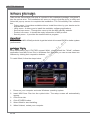
1
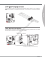
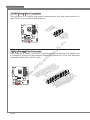
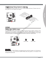
.e
u
ua
ls
an
em
ev
ic
.d
B75A-G43 series
w
w
w
MS-7758 (v2.x) Mainboard
Europe version
G52-77581X5
.e
u
ua
ls
English
w
w
w
.d
ev
ic
em
an
B75A-G43 Series
MS-7758 Mainboard
Mainboard Specifications
Processor Support
■ Support 3rd Generation Intel® Core™ i7/ Core™ i5/ Core™ i3/ Pentium®/ Celeron®
Processors for LGA 1155 socket
(For the latest information about CPU, please visit
http://www.msi.com/service/cpu-support)
Chipset
■ Intel® B75 chipset
Memory Support
.e
u
■ 4x DDR3 DIMMs support DDR3 1600/ 1333/ 1066 DRAM (32GB Max.)
■ Supports Dual-Channel mode, two DIMMs per channel
(For the latest information about memory, please visit
http://www.msi.com/service/test-report)
LAN
ua
ls
■ Supports LAN 10/100/1000 Fast Ethernet by Realtek® RTL8111E
Audio
an
■ Integrated HD audio codec by Realtek® ALC892
■ 8-channel audio with jack sensing
em
SATA
ev
ic
■ 1x SATA 6Gb/s port (SATA1) by Intel® B75
■ 5x SATA 3Gb/s ports (SATA2~6) by Intel® B75
USB 3.0
w
Multi-GPU
.d
■ 2x USB 3.0 rear IO ports by Intel® B75
■ 1x USB 3.0 onboard connector by Intel® B75
w
w
■ Supports AMD® CrossFire™ Technology
En-2
Connectors
.e
u
ua
ls
an
Slots
Form Factor
ev
ic
em
■ 1x PCIe 3.0 x16 slot, PCI_E2, it supports up to PCIe 3.0 x16 speed
■ 1x PCIe 2.0 x16 slot, PCI_E4, it supports up to PCIe 2.0 x4 speed
■ 2x PCIe 2.0 x1 slots
■ 3x PCI slots
■ ATX (30.5 cm X 24.4 cm)
w
w
w
.d
Mounting Screw Holes
■ 9x mounting holes
If you need to purchase accessories and request the part numbers, you could search
the product web page and find details on our web address http://www.msi.com/index.
php
En-3
English
■ Back panel
- 1x PS/2 keyboard/ mouse combo port
- 4x USB 2.0 ports
- 2x USB 3.0 ports
- 1x LAN port
- 1x HDMI port**, supporting a maximum resolution of 1920x1200
- 1x VGA port**
- 1x DVI-D port**, supporting a maximum resolution of 1920x1200
- 6x audio ports
(**This mainboard supports dual-display function by any two onboard graphics output
ports (HDMI+DVI,DVI+VGA or VGA+HDMI)).
■ On-Board
- 2x USB 2.0 connectors
- 1x USB 3.0 connector
- 1x TPM Module connector
- 1x Serial Port connector
- 1x Parallel Port connector
- 1x Front Panel Audio connector
- 1x Chassis Intrusion connector
- 1x Voice Genie connector (optional)
MS-7758 Mainboard
Connectors Quick Guide
JPWR2
DIMM3
CPU
SYSFAN3
DIMM2
DIMM1
DIMM4
CPUFAN
SYSFAN1
ua
ls
.e
u
Back Panel
an
PCI_E3
JBAT1
JCI1
.d
PCI1
w
SATA1/ 2
w
SATA3/ 4
SATA5/ 6
w
PCI2
JUSB3
ev
ic
PCI_E2
PCI_E4
SYSFAN2
em
PCI_E1
SYSFAN4
PCI3
JAUD1
JFP2
JFP1
JTPM1
JUSB1/ 2
JLPT1
JDLED3
JCOM1
En-4
JPWR1
Connectors Reference Guide
Page
Back Panel
I/O Ports
En-6
CPU LGA 1155 CPU Socket
En-9
CPUFAN,SYSFAN1~4
Fan Power Connectors
En-19
DIMM1~4
DDR3 Memory Slots
En-14
JAUD1
Front Panel Audio Connector
En-23
JBAT1
Clear CMOS Jumper
En-25
JCI1
Chassis Intrusion Connector
En-22
JCOM1
Serial Port Connector
JDLED3
Voice Genie Connector
JFP1, JFP2
Front Panel Connectors
En-20
JLPT1
Parallel Port Connector
En-24
JPWR1
ATX 24-pin Power Connector
En-13
JPWR2
ATX 8-pin Power Connector
En-13
ev
ic
em
an
ua
ls
.e
u
Port Type
JTPM1
En-24
En-25
TPM Module Connector
En-23
USB 2.0 Expansion Connectors
En-22
USB 3.0 Expansion Connector
En-21
PCI Expansion Slots
En-17
PCI_E2, PCI_E4
PCIe x16 Expansion Slots
En-16
PCI_E1, PCI_E3
PCIe x1 Expansion Slots
En-16
SATA1 SATA 6Gb/s Connector
En-18
SATA2~6
SATA 3Gb/s Connectors
En-18
.d
JUSB1~2
w
w
PCI1~3
w
JUSB3
En-5
English
Port Name
MS-7758 Mainboard
Back Panel Quick Guide
Mouse/ Keyboard
LAN
VGA Port
Line-In
USB 3.0 Port
RS-Out
Line-Out CS-Out
Mic
USB 2.0 Port USB 2.0 Port
SS-Out
DVI-D Port
HDMI Port
ua
ls
.e
u
▶ Mouse/Keyboard
A combination PS/2® mouse/keyboard DIN connector for a PS/2® mouse/keyboard.
Color
LED State
Left
Yellow
Off
LAN link is not established.
On(Steady)
LAN link is established.
Off
w
.d
100 Mbits/sec data rate
1000 Mbits/sec data rate
w
On
The computer is communicating with another computer on the network.
10 Mbits/sec data rate
On
Orange
ev
ic
On(flashing)
Green
Green/ Orange
em
LED
Right
Condition
Yellow
an
▶ LAN
The standard RJ-45 LAN jack is for connecting to
a Local Area Network (LAN).
w
▶ USB 2.0 Port
The USB 2.0 port is for attaching USB 2.0 devices such as keyboard, mouse, or other
USB 2.0-compatible devices.
▶ USB 3.0 Port
USB 3.0 port is backward-compatible with USB 2.0 devices. It supports data transfer
rate up to 5 Gbit/s (SuperSpeed).
Important
In order to use USB 3.0 devices, you must connect to a USB 3.0 port. If a USB cable is
used, it must be USB 3.0 compliant.
En-6
▶ HDMI Port
The High-Definition Multimedia Interface (HDMI) is an all-digital audio-video interface
that is capable of transmitting uncompressed streams. HDMI supports all types of TV
formats, including standard, enhanced, or high-definition video, plus multi-channel
digital audio on a single cable.
.e
u
▶ DVI-D Port
The DVI-D (Digital Visual Interface- Digital) connector can be connected to a LCD
monitor, or a CRT monitor with an adapter. To connect a monitor, please refer to the
monitor’s manual for more information.
Important
ua
ls
This platform supports dual-display function by any two output ports (HDMI+DVI,
DVI+VGA or VGA+HDMI).
HDMI+DVI
DVI+VGA
VGA+HDMI
◯
◯
◯
◯
◯
◯
an
em
Extend mode
(Extend the desktop to the second monitor)
ev
ic
Clone mode
(Two monitors have the same screen)
w
w
w
.d
▶ Audio Ports
These connectors are used for audio devices. The color of the jack refers to the function
of the connector.
■ Blue-Line in: Used for connecting external audio outputting devices.
■ Green- Line out: Used as a connector for speakers or headphone.
■ Pink- Mic: Used as a connector for a microphone.
■ Black- RS-Out: Rear surround sound line out in 4/ 5.1/ 7.1 channel mode.
■ Orange- CS-Out: Center/ subwoofer line out in 5.1/ 7.1 channel mode.
■ Gray- SS-Out: Side surround sound line out in 7.1 channel mode.
En-7
English
▶ VGA Port
The DB15-pin female connector is provided for monitor.
MS-7758 Mainboard
CPU (Central Processing Unit)
Introduction to the LGA 1155 CPU
The surface of the LGA 1155 CPU
has two alignment keys and a
yellow triangle to assist in correctly
lining up the CPU for mainboard
placement. The yellow triangle is the
Pin 1 indicator.
ua
ls
.e
u
Alignment Key
ev
ic
em
an
Yellow triangle is the
Pin 1 indicator
.d
Important
w
w
w
Overheating
Overheating can seriously damage the CPU and mainboard. Always make sure the
cooling fans work properly to protect the CPU from overheating. Be sure to apply an
even layer of thermal paste (or thermal tape) between the CPU and the heatsink to
enhance heat dissipation.
Replacing the CPU
When replacing the CPU, always turn off the system’s power supply and unplug the
power supply’s power cord to ensure the safety of the CPU.
Overclocking
This mainboard is designed to support overclocking. Before attempting to overclock,
please make sure that all other system components can tolerate overclocking. Any
attempt to operate beyond product specifications is not recommend. MSI does not
guarantee the damages or risks caused by inadequate operation beyond product
specifications.
En-8
CPU & Cooler Installation
When installing a CPU, always remember to install a CPU cooler. A CPU cooler is
necessary to prevent overheating and maintain system stability. Follow the steps below
to ensure correct CPU and CPU cooler installation. Wrong installation can damage both
the CPU and the mainboard.
ev
ic
em
an
ua
ls
.e
u
loading
2. The
plate
should
automatically lift up as the loading
lever is pushed to the fully open
position. Do not touch any of the
CPU socket pins.
4. Close the loading plate and remove
the plastic protective cap.
w
w
w
.d
3. Line up the CPU to fit the CPU
socket. Be sure to hold the CPU by
the base with the metal contacts
facing downward. The alignment
keys on the CPU will line up with the
edges of the CPU socket to ensure a
correct fit.
Alignment Key
En-9
English
1. Unhook and lift the loading lever to
the fully open position.
MS-7758 Mainboard
6. Evenly spread a thin layer of
thermal paste (or thermal tape) on
the top of the CPU. This will help in
heat dissipation and prevent CPU
overheating.
8. Place the heatsink on the mainboard
with the fan’s wires facing towards the
fan connector and the hooks matching
the holes on the mainboard.
w
w
w
.d
ev
ic
em
7. Locate the CPU fan connector on the
mainboard.
an
ua
ls
.e
u
5. Inspect the CPU to check if it is
properly seated in the socket. Press
the loading lever down and lock it
under the retention tab.
En-10
9. Push down on the heatsink until the
four clips get wedged into the holes
on the mainboard. Press the four
hooks down to fasten the cooler. As
each hook locks into position a click
should be heard.
10. Inspect the mainboard to ensure that
the clip-ends have been properly
locked in place.
English
Mainboard
an
w
w
w
.d
ev
ic
em
11. Finally, attach the CPU fan cable
to the CPU fan connector on the
mainboard.
ua
ls
.e
u
Hook
Important
• Do not touch the CPU socket pins.
• Confirm that the CPU cooler has formed a tight seal with the CPU before booting
your system.
• Whenever the CPU is not installed, always protect the CPU socket pins by covering
the socket with the plastic cap.
• Please refer to the documentation in the CPU cooler package for more details about
CPU cooler installation.
En-11
MS-7758 Mainboard
Mounting Screw Holes
When installing the mainboard, first install the necessary mounting stands required for
a mainboard on the mounting plate in your computer case. If there is an I/O back plate
that came with the computer case, please replace it with the I/O backplate that came
with the mainboard package. The I/O backplate should snap easily into the computer
case without the need for any screws. Align the mounting plate’s mounting stands with
the screw holes on the mainboard and secure the mainboard with the screws provided
with your computer case. The locations of the screw holes on the mainboard are shown
below. For more information, please refer to the manual that came with the computer
case.
w
w
w
.d
ev
ic
em
an
ua
ls
.e
u
The I/O ports should be facing toward
the rear of the computer case. They
should line up with the holes on the
I/O backplate.
Important
• Install the mainboard on a flat surface free from unnecessary debris.
• To prevent damage to the mainboard, any contact between the mainboard circuitry
and the computer case, except for the mounting stands, is prohibited.
• Please make sure there are no loose metal components on the mainboard or within
the computer case that may cause a short circuit of the mainboard.
En-12
Power Supply
JPWR1: ATX 24-pin Power Connector
an
ua
ls
.e
u
d
n
u
ro
V
.G 5 V
4
2 3.+ +5 V
d
2 2. +5 s un d
2 1. e o n d
2 0.R Gr rou un #
2 9. G ro ON d
- n
1 8.
1 7.G PS ou
1 6. Gr 2V V
1 . 1 .3
5
1 4.- +3
1 3.
1
V
.3
3 V
.+ 2 V
2 1 2
1 1.+ +1 B OK
1 0. VS R nd
1 .5 W u
9 .P ro nd
8 .G 5V u
d
7 .+ ro
6 .G 5V un
5 .+ ro 3V
4 G . V
.
3 .+3 3.3
2 .+
1
em
JPWR2: ATX 8-pin Power Connector
.d
w
w
V
2
1 V
.+ 2 V
8 .+1 2 V
7 .+1 12
6 .+
5
w
d
n
u d
ro un nd
.G ro u d
4 .G ro un
3 .G ro
2 .G
1
ev
ic
This connector provides 12V power to the CPU.
Important
Make sure that all the power cables are securely connected to a proper ATX power
supply to ensure stable operation of the mainboard.
En-13
English
This connector allows you to connect an ATX 24-pin power supply. To connect the ATX
24-pin power supply, align the power supply cable with the connector and firmly press
the cable into the connector. If done correctly, the clip on the power cable should be
hooked on the mainboard’s power connector.
MS-7758 Mainboard
Memory
These DIMM slots are used for installing memory modules. For more information on
compatible components, please visit http://www.msi.com/service/test-report
DDR3
240-pin, 1.5V
48x2=96 pin
72x2=144 pin
Dual-Channel mode Population Rule
1
ua
ls
.e
u
In Dual-Channel mode, the memory modules can transmit and receive data with two
data bus channels simultaneously. Enabling Dual-Channel mode can enhance system
performance. The following illustrations explain the population rules for Dual-Channel
mode.
an
2
DIMM4
ev
ic
DIMM2
DIMM3
DIMM4
w
w
w
DIMM1
.d
DIMM2
DIMM3
em
DIMM1
Installed
Empty
Important
• DDR3 memory modules are not interchangeable with DDR2, and the DDR3 standard
is not backward compatible. Always install DDR3 memory modules in DDR3 DIMM
slots.
• To ensure system stability, memory modules must be of the same type and density
in Dual-Channel mode.
• Due to chipset resource usage, the system will only detect up to 31+ GB of memory
(not full 32 GB) when all DIMM slots have 8GB memory modules installed.
En-14
Installing Memory Modules
1. Unlock the DIMM slot by pushing the mounting clips to the side. Vertically insert the
memory module into the DIMM slot. The memory module has an off-center notch on
the bottom that will only allow it to fit one way into the DIMM slot.
em
an
ua
ls
.e
u
3. Manually check if the memory module has been locked in place by the DIMM slot’s
side clips.
w
w
w
.d
ev
ic
Notch
Volt
En-15
English
2. Push the memory module deep into the DIMM slot. The plastic clips at each side
of the DIMM slot will automatically close when the memory module is properly seat
and an audible click should be heard.
MS-7758 Mainboard
Expansion Slots
This mainboard contains numerous ports for expansion cards, such as discrete graphics
or audio cards.
PCIe (Peripheral Component Interconnect Express) Slot
The PCIe slot supports the PCIe interface expansion card.
ua
ls
.e
u
PCIe 3.0 x16 Slot
w
w
w
.d
ev
ic
em
an
PCIe 2.0 x16 Slot
En-16
PCIe 2.0 x1 Slot
PCI (Peripheral Component Interconnect) Slot
The PCI slot supports additional LAN, SCSI, USB, and other add-on cards that comply
with PCI specifications.
English
32-bit PCI Slot
Important
PCI Interrupt Request Routing
an
ua
ls
.e
u
When adding or removing expansion cards, always turn off the power supply and
unplug the power supply power cable from the power outlet. Read the expansion card’s
documentation to check for any necessary additional hardware or software changes.
Order1
Order2
Order3
Order4
INT D#
INT A#
INT B#
INT C#
PCI Slot2
INT B#
INT C#
INT D#
INT A#
PCI Slot3
INT C#
INT D#
INT A#
INT B#
w
w
w
.d
PCI Slot1
ev
ic
em
IRQ, or interrupt request lines, are hardware lines over which devices can send interrupt
requests to the processor. The PCI IRQ pins are typically connected to the PCI bus pins
as followed:
En-17
MS-7758 Mainboard
Internal Connectors
SATA1~6: SATA Connector
an
ua
ls
.e
u
This connector is a high-speed SATA interface port. Each connector can connect to one
SATA device. SATA devices include disk drives (HDD), solid state drives (SSD), and
optical drives (CD/ DVD/ Blu-Ray).
em
* The MB layout in this figure is for reference only.
SATA2
ev
ic
SATA4
SATA6
SATA1
SATA2~6 (3Gb/s)
.d
SATA3
SATA1 (6Gb/s)
Important
w
w
w
SATA5
• Many SATA devices also need a power cable from the power supply. Such devices
include disk drives (HDD), solid state drives (SSD), and optical drives (CD / DVD /
Blu-Ray). Please refer to the device’s manual for further information.
• Many computer cases also require that large SATA devices, such as HDDs, SSDs,
and optical drives, be screwed down into the case. Refer to the manual that came
with your computer case or your SATA device for further installation instructions.
• Please do not fold the SATA cable at a 90-degree angle. Data loss may result during
transmission otherwise.
• SATA cables have identical plugs on either sides of the cable. However, it is
recommended that the flat connector be connected to the mainboard for space
saving purposes.
En-18
CPUFAN,SYSFAN1~4: Fan Power Connectors
CPUFAN
w
w
.d
ev
ic
d
n
u ol
ro ntr or
.G o s e
1 .C en us
2 .S o
3 .N
4
em
an
ua
ls
.e
u
d
n
u
ro 2V or l
.G 1 s o
1 .+ en tr
2 .S on
3 .C
4
SYSFAN1/ SYSFAN2
w
SYSFAN3/ SYSFAN4
e se
g U
d a
n lt o
u o /N
ro N V or
.G A s
1 .F en
2 .S
3
Important
• Please refer to your processor’s official website or consult your vendor to find
recommended CPU cooling fans.
• The CPUFAN connector supports Smart Fan Control with linear mode. The Control
Center II utility can be installed to automatically control the fan speeds according to
the CPU’s temperature.
• If there are not enough ports on the mainboard to connect all system fans, adapters
are available to connect a fan directly to a power supply.
• Before first boot up, ensure that there are no cables impeding any fan blades.
En-19
English
The fan power connectors support system cooling fans with +12V. If the mainboard has
a System Hardware Monitor chipset on-board, you must use a specially designed fan
with a speed sensor to take advantage of the CPU fan control. Remember to connect
all system fans. Some system fans may not connect to the mainboard and will instead
connect to the power supply directly. A system fan can be plugged into any available
system fan connector.
MS-7758 Mainboard
JFP1, JFP2: Front Panel Connectors
These connectors connect to the front panel switches and LEDs. The JFP1 connector is
compliant with the Intel® Front Panel I/O Connectivity Design Guide. When installing the
front panel connectors, please use the enclosed mConnectors to simplify installation.
Plug all the wires from the computer case into the mConnectors and then plug the
mConnectors into the mainboard.
Spe
ake
r
zer
2
.+
8
.6 .+
4 .
Buz
P
o
w
e
r
in
P o 8. +
.
.N
6
0
.
4 +
.
2
e
ch
w
it
o
w
1
S
P
ua
ls
.e
u
D D
in E LE
P rL d
o e n
.N w e d
7 .Po sp n
5 u rou
S
.
3 .G
1
JFP2
r
E
an
L
ev
ic
w
w
Important
w
.d
ch
it
d Sw
e
t
rv e
D
s
E
se e
L
e R
D
.R
D
9
+
H
.
7 .5 .
3 .+
1
em
D
JFP1
• On the connectors coming from the case, pins marked by small triangles are positive
wires. Please use the diagrams above and the writing on the mConnectors to
determine correct connector orientation and placement.
• The majority of the computer case’s front panel connectors will primarily be plugged
into JFP1.
En-20
JUSB3: USB 3.0 Expansion Connector
The USB 3.0 port is backwards compatible with USB 2.0 devices. It supports data
transfer rates up to 5Gbits/s (SuperSpeed).
ua
ls
.e
u
English
115V
ev
ic
.d
w
N
D
_ DP
N
r X _
D
e R X
_ P
w _
o B3 _R _C _D
.P S 3 d X C
1 .U SB un T _
2 .U ro 3_ TX
3 .G SB 3_ d 4 .U B n 0
5 US rou 2. 0 +
.
6 G B 2. nd
S
.
7 U B u
. S
8 .U ro
9 0.G
1
em
an
N
D
_ DP
in
N
P r X _
D
o e _R X
_ P
C D
.N w 3 R
_ _
0 o B _
2 .P S B3 nd X _C
T
9
1 8.U S ou _ X
1 7.U Gr B3 _T
1 6. S B3 nd 1 .U S u .0 +
o
5
1 4.U r B2 .0
1 3.G S B2
1 2.U S
1 1.U
1
* The MB layout in this figure is for reference only.
w
w
USB 3.0 Bracket (optional)
Important
• Note that the VCC and GND pins must be connected correctly to avoid possible
damage.
• To use a USB 3.0 device, you must connect the device to a USB 3.0 port through an
optional USB 3.0 compliant cable.
En-21
MS-7758 Mainboard
JUSB1~2: USB 2.0 Expansion Connectors
This connector is designed for connecting high-speed USB peripherals such as USB
HDDs, digital cameras, MP3 players, printers, modems, and many others.
115V
d
C un +
.N o 1
0 r B 11 .G
8 US B
. S
6 .U C
4 VC
.
2
.e
u
in
P nd
o u +
.N ro 0
9 G B 0.
7 .US B
S
5 .U CC
3 .V
1
* The MB layout in this figure is for reference only.
ua
ls
USB 2.0 Bracket (optional)
an
Important
ev
ic
em
Note that the VCC and GND pins must be connected correctly to avoid possible
damage.
.d
JCI1: Chassis Intrusion Connector
w
w
w
This connector connects to the chassis intrusion switch cable. If the computer case is
opened, the chassis intrusion mechanism will be activated. The system will record this
intrusion and a warning message will flash on screen. To clear the warning, you must
enter the BIOS utility and clear the record.
d
n
u RU
ro T
.G IN
2 .C
1
En-22
JAUD1: Front Panel Audio Connector
This connector allows you to connect the front audio panel located on your computer
case. This connector is compliant with the Intel® Front Panel I/O Connectivity Design
Guide.
io
English
ct
te
e
D
e
n
o
n
h
io
P
ct
d
e
a
e in et
.H P D
0 o
1 .N IC
d
8 M
n
.
C
6 .N ou
4 Gr
.
2
n
em
an
ua
ls
.e
u
L
e D
n
o N
h E R
P _S ne
d
o
a E h
e NS P
.H E d
9 .S ea R
7 .H IC L
5 .M IC
3 .M
1
JTPM1: TPM Module Connector
ev
ic
This connector connects to a TPM (Trusted Platform Module). Please refer to the TPM
security platform manual for more details and usages.
w
w
115V
w
.d
TPM module is optional
3
in
p 2
ta in
a p 1
d ta pin 0
n
e s & da ta pi
m s & da ta
a
ra re s
F d s & d
C ad dre ss &
P
re s
.L C d d s
3 P a d re
1 1.L C a dd et
1 .LP C a es k
9 .LP C R loc
7 .LP C C
5 .LP C
3 .LP
1
d
n
u d
r
ro un n r
e
.G ro Pi we Q r ow
4
1 2.G o Po IR we y p
l
1 .N
a o b
V
i
0
1 .5 er P nd
8 .S 3V ta
6 .3. S
4 .3V
2
* The MB layout in this figure is for reference only.
En-23
MS-7758 Mainboard
JCOM1: Serial Port Connector
This connector is a 16550A high speed communication port that sends/receives 16
bytes FIFOs. You can attach a serial device.
in
P
o
.N S
0 T R
1 .C S
8 D R
.
6 T
.D N
4 SI
.
2
ua
ls
.e
u
I S d
.R T n
9 . R r ou T
7 .G U
5 .SO C D
3 .D
1
JLPT1: Parallel Port Connector
w
En-24
T
C
L
Y
.S
5 E S
2 3.P U K# 7
2 1.B C ND 6
2 9.A R ND 5
1 .P R ND 4
7
1 5.P R ND 3
1 .P
3 R D 2
1 1.P RN D 1
1 .P N D
9 .PR N D0
7 .PR N B#
5 .PR ST
3 .R
1
w
w
.d
in
P d
o un d
.N ro un d
6
2 4.G ro un d
2 2.G ro un d
2 0.G ro un d
2 .G r o u n d
8
#
1 6 . G r o u n d IN
1 .G ro un L
4
S
1 2.G ro _ #
1 0.G PT IT
1 .L IN #
8 .P R #
6 ER D
.
4 .AF
2
ev
ic
em
an
This connector is used to connect an optional parallel port bracket. The parallel port
is a standard printer port that supports Enhanced Parallel Port (EPP) and Extended
Capabilities Parallel Port (ECP) mode.
JDLED3: Voice Genie Connector (optional)
This connector is used to link to the voice control module (optional). Please refer to its
user guide for more details and usages.
.e
u
ua
ls
an
em
JBAT1: Clear CMOS Jumper
w
w
w
.d
ev
ic
There is CMOS RAM onboard that is external powered from a battery located on the
mainboard to save system configuration data. With the CMOS RAM, the system can
automatically boot into the operating system (OS) every time it is turned on. If you want
to clear the system configuration, set the jumpers to clear the CMOS RAM.
1
Keep Data
1
Clear Data
Important
You can clear the CMOS RAM by shorting this jumper while the system is off. Afterwards,
open the jumper . Do not clear the CMOS RAM while the system is on because it will
damage the mainboard.
En-25
English
in
p
d
n d
u ve
r
ro se d in
p
.G e n l in
u
p
3
1 1.R ro tro l pin
1 .G on tro l
9 .C on tro
7 .C n B
o S
5
C
.
3 .5V
1
in
p n
l i
o p
tr l
n o
in
o tr
p
n
n
.C o Pi ol
4
in
1 2.C o tr
p
1 .N n 3 l pin
o
0
1 .C CC tro l
8 .V n ro
t
6 o n
C
.
4 .Co
2
Jumper
MS-7758 Mainboard
BIOS Setup
CLICK BIOS II is developed by MSI that provides a graphical user interface for setting
parameters of BIOS by using the mouse and the keybord.
With the CLICK BIOS II, users can change BIOS settings, monitor CPU temperature,
select the boot device priority and view system information such as the CPU name,
DRAM capacity, the OS version and the BIOS version. Users can import and export
parameters data for backup or sharing with friends. After connecting to Internet, users
can browse the internet, check mail and live update your system.
Entering
.e
u
Power on the computer and the system will start POST (Power On Self Test) process.
When the message below appears on the screen, press <DEL> key to enter Setup.
ua
ls
Press DEL key to enter Setup Menu, F11 to enter Boot Menu
em
an
If the message disappears before you respond and you still wish to enter Setup, restart
the system by turning it OFF and On or pressing the RESET button. You may also
restart the system by simultaneously pressing <Ctrl>, <Alt>, and <Delete> keys.
ev
ic
Important
w
w
w
.d
The items under each BIOS category described in this chapter are under continuous
update for better system performance. Therefore, the description may be slightly
different from the latest BIOS and should be held for reference only.
En-26
Overview
After entering CLICK BIOS II, the following screen is displayed.
System
information
Temperature
monitor
Boot device
priority bar
BIOS menu
selection
ua
ls
.e
u
BIOS menu
selection
em
an
Menu display
Important
ev
ic
The pictures in this guide are for reference only and may vary from the product you
purchased. Please refer to the actual screens of your system for detailed information.
w
w
w
.d
▶ Temperature monitor
This block shows the temperature of the processor and the mainboard.
▶ System information
This block shows the time, date, CPU name, CPU frequency, DRAM frequency, DRAM
capacity and the BIOS version.
▶ BIOS menu selection
These blocks are used to select menus of BIOS. The following options are available:
■ SETTINGS - Use this menu to specify your settings for chipset features, boot
device.
■ OC - This menu contains items of the frequency and voltage adjustments.
Increasing the frequency can get better performance, however high frequency
and heat can cause instability, we do not recommend general users to
overclock.
■ ECO - This menu is related to energy-saving settings.
■ BROWSER - This feature is used to enter the MSI Winki web browser.
■ UTILITIES - This menu contains utilities for backup and update.
■ SECURITY - The security menu is used to keep unauthorized people from
making any changes to the settings. You can use these security features to
protect your system.
En-27
English
Boot menu
Mode
selection
MS-7758 Mainboard
▶ Boot device priority bar
You can move the device icons to change the boot priority.
▶ Boot menu
This button is used to open a boot menu. Click the item to boot the system from the
device instantly.
▶ Mode selection
This feature allows you to load presets of energy saving or overclocking.
▶ Menu display
This area provides BIOS setting menu that allows you to change parameters.
Boot device priority bar
ua
ls
High priority
.e
u
This bar shows the priority of the boot devices. The light icons indicate that the
devices are available.
Low priority
an
Click and draw the icon to left or right to specify the boot priority.
em
Sub-Menu
w
General Help
w
.d
ev
ic
An arrow symbol appears to the left of certain fields that means it contains a sub-menu.
A sub-menu contains additional options for a field parameter. You can use arrow keys
( ↑↓ ) or mouse to highlight the field and press <Enter> or mouse double left click to
enter the sub-menu. If you want to return to the previous menu, just press the <Esc >
or click the right mouse button.
w
CLICK BIOS II provides General Help window. You can call up the window from any
BIOS menu by simply pressing <F1> or click HELP on BIOS setting screen. The Help
window lists the appropriate keys to use and the possible selections for the highlighted
item.
En-28
Operation
CLICK BIOS II allows you to control BIOS settings with the mouse and the keyboard.
The following table lists and describes the hot keys and the mouse operations.
Hot key
Mouse
Description
<↑↓→← >
Select Item
English
Move the cursor
Select Icon/ Field
<Enter>
<Esc>
.e
u
Click/ Doubleclick the left
button
ua
ls
Jump to the Exit menu or return to the previous from
a submenu
an
Click the right
button
Increase the numeric value or make changes
<->
Decrease the numeric value or make changes
ev
ic
em
<+>
<F1>
General Help
<F4>
CPU Specifications
<F12>
w
w
<F10>
Enter Memory-Z
w
<F6>
.d
<F5>
Load optimized defaults
Save Change and Reset
Save a screenshot to a FAT/FAT32 USB drive
En-29
MS-7758 Mainboard
OC Menu
an
ua
ls
.e
u
This menu is for advanced users who want to overclock the mainboard.
em
Important
ev
ic
• Overclocking your PC manually is only recommended for advanced users.
• Overclocking is not guaranteed, and if done improperly, can void your warranty or
severely damage your hardware.
w
.d
• If you are unfamiliar with overclocking, we advise you to use OC Genie for easy
overclocking.
w
w
▶ Current CPU/ DRAM Frequency
These items show the current clocks of CPU and Memory speed. Read-only.
▶ Adjust CPU Ratio
Controls the multiplier that is used to determine internal clock speed of the processor.
This feature can only be changed if the processor supports this function.
▶ Adjusted CPU Frequency
It shows the adjusted CPU frequency. Read-only.
▶ Adjust CPU Ratio in OS
Enable this item to allow CPU ratio changes in the OS by using MSI Control Center II.
▶ Internal PLL Overvoltage
This item is used to adjust the PLL voltage.
▶ EIST
Enhanced Intel SpeedStep technology allows you to set the performance level of the
microprocessor whether the computer is running on battery or AC power. This field only
appears with installed CPUs that support this technology.
En-30
▶ Intel Turbo Boost
Enables or disables Intel Turbo Boost which automatically boosts CPU performance
above rated specifications (when applications requests the highest performance state
of the processor).
▶ Adjusted DRAM Frequency
It shows the adjusted DRAM frequency. Read-only.
ua
ls
.e
u
▶ DRAM Timing Mode
Select whether DRAM timing is controlled by the SPD (Serial Presence Detect)
EEPROM on the DRAM module. Setting to [Auto] enables DRAM timings and the
following “Advanced DRAM Configuration” sub-menu to be determined by BIOS based
on the configurations on the SPD. Selecting [Link] or [Unlink] allows users to configure
the DRAM timings for each channel and the following related “Advanced DRAM
Configuration” sub-menu manually.
▶ Advanced DRAM Configuration
Press <Enter> to enter the sub-menu.
em
an
▶ Command Rate
This setting controls the DRAM command rate.
ev
ic
▶ tCL
Controls CAS latency which determines the timing delay (in clock cycles) of starting
a read command after receiving data.
w
.d
▶ tRCD
Determines the timing of the transition from RAS (row address strobe) to CAS
(column address strobe). The less clock cycles, the faster the DRAM performance.
w
w
▶ tRP
Controls number of cycles for RAS (row address strobe) to be allowed to pre-charge.
If insufficient time is allowed for RAS to accumulate before DRAM refresh, the DRAM
may fail to retain data. This item applies only when synchronous DRAM is installed
in the system.
▶ tRAS
Determines the time RAS (row address strobe) takes to read from and write to
memory cell.
▶ tRFC
This setting determines the time RFC takes to read from and write to a memory
cell.
▶ tWR
Determines minimum time interval between end of write data burst and the start of a
pre-charge command. Allows sense amplifiers to restore data to cell.
En-31
English
▶ DRAM Frequency
This item allows you to adjust the DRAM frequency. Please note the overclocking
behavior is not guaranteed.
MS-7758 Mainboard
▶ tWTR
Determines minimum time interval between the end of write data burst and the start
of a column-read command; allows I/O gating to overdrive sense amplifies before
read command starts.
▶ tRRD
Specifies the active-to-active delay of different banks.
▶ tRTP
Time interval between a read and a precharge command.
▶ tFAW
This item is used to set the tFAW (four activate window delay) timing.
▶ tWCL
This item is used to set the tWCL (Write CAS Latency) timing.
ev
ic
em
an
ua
ls
.e
u
▶ Advanced Channel 1/ 2 Timing Configuration
Press <Enter> to enter the sub-menu. And you can set the advanced memory timing
for each channel.
▶ GT OverClocking
This item allows you to enable/ disable the overclocking of integrated graphics.
▶ GT Ratio
This setting controls the ratio of integrated graphics frequency to enable the integrated
graphics to run at different frequency combinations.
▶ Adjusted GT Frequency
It shows the iGPU frequency. Read-only.
w
w
Important
.d
▶ Spread Spectrum
This function reduces the EMI (Electromagnetic Interference) generated by modulating
clock generator pulses.
w
• If you do not have any EMI problem, leave the setting at [Disabled] for optimal system
stability and performance. But if you are plagued by EMI, select the value of Spread
Spectrum for EMI reduction.
• The greater the Spread Spectrum value is, the greater the EMI is reduced, and the
system will become less stable. For the most suitable Spread Spectrum value, please
consult your local EMI regulation.
• Remember to disable Spread Spectrum if you are overclocking because even a slight
jitter can introduce a temporary boost in clock speed which may just cause your
overclocked processor to lock up.
▶ CPU Core Voltage/ DRAM Voltage.
These items are used to adjust the voltage of CPU and Memory.
▶ Current CPU Core Voltage/ Current DRAM Voltage
These items show current CPU/ DRAM voltage. Read-only.
En-32
▶ Overclocking Profiles
Press <Enter> to enter the sub-menu.
▶ Overclocking Profile 1/ 2/ 3/ 4/ 5/ 6
Press <Enter> to enter the sub-menu.
English
▶ Set Name for Overclocking Profile 1/ 2/ 3/ 4/ 5/ 6
Give a name by typing in this item.
▶ Save Overclocking Profile 1/ 2/ 3/ 4/ 5/ 6
Save the current overclocking settings to ROM for selected profile.
▶ Load/ Clear Overclocking Profile 1/ 2/ 3/ 4/ 5/ 6
Load/ Clear the stored profile settings from ROM.
▶ OC Profile Load from USB
Load the stored settings from USB flash disk.
.e
u
▶ OC Profile Save to USB
Save the current overclocking settings to USB flash disk.
an
ua
ls
▶ CPU Specifications
Press <Enter> to enter the sub-menu. This sub-menu highlights all the key features of
your CPU. The information will vary by model and is read-only. You can also access this
information at any time by pressing [F4]. Press <Enter> to enter the sub-menu.
ev
ic
em
▶ CPU Technology Support
Press <Enter> to enter the sub-menu. The sub-menu shows the installed CPU
technologies. Read only.
w
.d
▶ MEMORY-Z
Press <Enter> to enter the sub-menu. This sub-menu highlights all the settings and
timings of your DIMMs. This information will vary by model and is read-only. You can
also access this information at any time by pressing [F5]. Press <Enter> to enter the
sub-menu.
w
w
▶ DIMM1~4 Memory SPD
Press <Enter> to enter the sub-menu. The sub-menu displays the informations of
installed memory.
▶ CPU Features
Press <Enter> to enter the sub-menu.
▶ Active Processor Cores
This item allows you to select the number of active processor cores.
▶ Limit CPUID Maximum
It is designed to limit the listed speed of the processor to older operating systems.
En-33
MS-7758 Mainboard
▶ Execute Disable Bit
Can prevent certain classes of malicious “buffer overflow” attacks where worms
can try to execute code to damage your system. It is recommended you keep this
enabled always.
▶ Intel Virtualization Tech
Enhances virtualization and allows the system to act as multiple virtual systems. See
Intel’s official website for more information.
▶ Intel VT-D Tech
This item is used to enable/disable the Intel VT-D technology. For further information
please refer to Intel’s official website.
▶ Power Technology
This item allows you to select the Intel Dynamic Power technology mode.
.e
u
▶ C1E Support
Enable system to reduce CPU power consumption while idle. Not all processors
support Enhanced Halt state (C1E).
an
ua
ls
▶ OverSpeed Protection
Monitors current CPU draw as well as power consumption; if it exceeds a certain
level, the processor automatically reduces its clock speed. For overclocking, it is
recommended this feature is disabled.
ev
ic
em
▶ Intel C-State
C-state is a power management state that detects when the system is idle and
lowers power consumption accordingly.
▶ Package C State limit
This field allows you to select a C-state mode.
w
.d
▶ Long duration power limit (W)
This field allows you to adjust the TDP power limit for the long duration.
w
w
▶ Long duration maintained (s)
This field allows you to adjust the maintaining time for long duration power limit.
▶ Short duration power limit (W)
This field allows you to adjust the TDP power limit for the short duration.
▶ Primary/ Secondary Plane Current value (A)
These fields allow you to adjust over current value of CPU (primary plane)/ iGPU
(secondary plane) for turbo ratio.
▶ Primary/ Secondary plane turbo power limit (W)
These fields allow you to adjust the turbo power limit of CPU (primary plane)/ iGPU
(secondary plane) for turbo boost.
En-34
Updating the BIOS with Live Update
This section tells you how to update the BIOS by using the Live Update utility before
entering Operating System. Live Update will update the BIOS automatically when
connecting to the Internet. To update the BIOS with the Live Update utility:
1. Click Live Update button
installed).
on the BIOS UTILITIES menu. (The Winki must be
ua
ls
.e
u
English
3. Click the next button
.
if necessary.
an
2. Setup the connection by click the setting button
w
w
w
.d
ev
ic
em
4. Live Update will automatically detect the version of BIOS and download the
appropriate file.
5. Click the confirm button
to update the BIOS.
Important
Do not update the BIOS if your system is running fine.
En-35
MS-7758 Mainboard
Software Information
Take out the Driver/Utility Disc that is included in the mainboard package, and place it
into the optical drive. The installation will auto-run, simply click the driver or utility and
follow the pop-up screen to complete the installation. The Driver/Utility Disc contains
the:
- Driver menu : It provides available drivers. Install the driver by your desire and to
activate the device.
- Utility menu : It allows you to install the available software applications.
- Service base menu : Through this menu to link the MSI officially website.
- Product info menu : It shows the newly information of MSI product.
- Security menu : It provides the useful antivirus program.
Important
.e
u
Please visit the MSI officially website to get the latest drivers and BIOS for better system
performance.
ua
ls
Installing Winki
em
an
BIOS BROWSER and UTILITIES request Winki, please install the "Winki" software
application from MSI Driver Disc in Windows first. And then you can access these two
features by clicking their respective buttons.
w
w
w
.d
ev
ic
To install Winki, follow the steps below:
1. Power on your computer and enter Windows operating system.
2. Insert MSI Driver Disc into the optical drive. The setup screen will automatically
appear.
3. Click Driver tab.
4. Click OTHERS button.
5. Select Winki to start installing.
6. When finished, restart your computer.
En-36