1
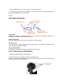
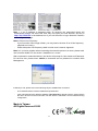
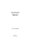
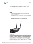
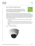
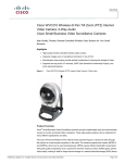
H.264 Mega-Pixel / Multi-Profile
Network Cameras
Quick Start Guide
2009 Nov.
Table of Contents
1. System Requirements ......................................................................................................... 3
2. Physical Installation............................................................................................................ 4
2.1 Dome Type Cameras........................................................................................... 4
2.1.1 Indoor Dome Camera Installation ................................................................. 5
2.1.2 Vandal (IR) Dome Camera Installation......................................................... 5
2.2 P/T Camera ......................................................................................................... 7
2.2.1 P/T Camera Installation ................................................................................. 7
2.3 Vandal PT Cameras............................................................................................. 8
2.3.1 Vandal P/T Camera Installation .................................................................... 9
2.4 Box and Gun Type Cameras ............................................................................. 10
2.4.1 Box and Gun Type Camera Installation ...................................................... 11
2.5 Outdoor IR Cameras..........................................................................................11
2.5.1 Outdoor IR Camera Installation .................................................................. 11
2.6 Cube Cameras................................................................................................... 12
2.6.1 Cube Camera Installation ............................................................................ 12
3. Camera administration...................................................................................................... 13
2
About multi-profile
Multi-profile stands for simultaneously video streams. These Network Cameras can generate H.264,
MPEG4 and MJPEG streaming simultaneously to different clients. Moreover, the resolution can be
different from one client to another. This state-of-art design is considerable to fit in various network
environments.
Before Installation
Before installation, please be sure to read this quick installation guide and user’s manual carefully
to complete machine installation.
1. System Requirements
Mega-Pixel / Multi-Profile Network Cameras
Network Environment
Network Interface
LAN Model
WLAN Model
10/100MBase-TX Ethernet
10/100MBase-TX Ethernet
802.11b/g or n WLAN
Monitoring System Recommended for Internet Explorer 6.0 or later
System Hardware
· CPU: Pentium 4, 2GHz or above
· Memory Size : 512 MB or above
· VGA card resolution : 1024 x 768 or above
- Sound card: for 2-way audio function
System Requirement for Viewer & Recorder Application
Support OS
Win XP, Win Vista
System Hardware
16 cameras surveillance application
· CPU: Pentium Duo, 2.8GHz or faster
· Memory Size : 1GB or above
· VGA card resolution : 1024 x 768 or above
System Requirement for Viewer & Recorder Application
Support OS Win XP, Win Vista
FPS
~120
120~360
360~540
540~960
960~
(QVGA)
CPU
Intel P4
Intel P4
Intel Pentium D Intel core 2 Duo Intel core 2 Quad
Q9650
E8600
2.4GHz
3.2GHz
950
3.0GHZ
3.3GHZ
3.4GHZ
RAM
512MB
512MB
1GB
2GB
2GB
Display
OS
support1024x768 resolution or above
Support DirectX 9.0c or above
Intel 945G or Intel 965G or above
Windows XP,Vista
Hard disk
Ethernet
Chipset
60GB
100Mbps
1Gbps
Intel 945 or Intel 965 or above
3
2. Physical Installation
2.1 Dome Type Cameras
1. RJ45 LAN socket: Connect to PC or Hub/Switch.
For connections to 10Base-T Ethernet or 100Base-TX Fast Ethernet cabling. This Ethernet
port built N-Way protocol can detect or negotiate the transmission speed of the network
automatically. Please use Category 5 cable to connect the Network Camera to a 100Mbps
Fast Ethernet network switch or hub.
In the LAN socket, there are two LEDs embedded:
LAN LED (green color)
This LED will be flashing while network accessing via Ethernet.
Power or Wireless LED (orange color)
This LED is used to indicate whether DC power is on or not. In addition, this LED will be flashing
while the wireless accessing of the Camera.
RS485 &
DI/DO
MIC in
Line out
12V DC in
RJ45
Factory
Default Reset
2. RS-485: Connect to a local keyboard controller.
DI/ DO: Connect to sensor in and alarm out devices
Cable for I/O connectors:
Name
Cable Color
12VDC Brown/White
GND
Blue/White
D+
Purple/White
DGray
DI
Green/White
DO
Orange/White
Function
DC 12V (50mA maximum)
GND
RS485 data +
RS485 data Digital signal input
Digital signal (alarm) output
3. Factory Default Reset
This button is used to restore the all factory default settings.
4. DC-in Jack
The input power is 12VDC. Note that supply the power to the Network Camera with the
4
power adapter included in package.
5. MIC in (audio in)
Connect a microphone to the network camera.
6. Line out (audio out)
Connect a loud speaker to the network camera. This function is for voice alerting and
two-way audio.
2.1.1 Indoor Dome Camera Installation
1. Please select the most suitable position on the wall or ceiling to install the camera.
2. Rotate the dome housing counterclockwise to remove it from the mounting base.
3. Set the mounting base onto the wall or ceiling and center it over the mounting hole,
using the two retaining screws for the main body, supplied by the appurtenance bag.
4. For lens adjustment, move the camera body and set the focus by turning the lens to the
left or right direction. When the camera focus adjustment has been completed, rotate
the dome housing clockwise to secure it to the mounting base
5. Connect the LAN cable to Ethernet’s switch or hub and the DC-Jack to the power
source. And connect the other cables and connectors if necessary.
6. Done.
2.1.2 Vandal (IR) Dome Camera Installation
1. Use the provided L-wrench, loosen the tamper-resistant housing cover (with screws still
attached on the cover). The unit has a factory installed side conduit entry and one may
adjust the cables to back conduit entry according to installation requirement.
5
2. Set the mounting base onto the wall or ceiling and center it over the mounting hole, using the
supplied four retaining screws to secure the main body.
3. Set the proper image by moving the camera body (some model may limit the PCB board
to180°rotational adjustment) and set the focus by turning the lens to the left or right
direction.
4. When the camera focus adjustment has been completed, use the provided L-wrench to
fasten the tamper-resistant housing to the main body.
5. Vari-Focal Dome Operation Guide: Once the picture appears on the monitor, open the
cover and adjust the lens wrench to “NEAR←→FAR”, get the view zoom that you desire,
and then adjust the focus wrench of the lens to obtain the best picture. After adjustment,
tighten both wrenches.
6. Must connect the LAN cable to Ethernet’s switch or hub and the DC-Jack to the power
source. And connect the other cables and connectors if necessary.
6
7. Done
2.2 P/T Camera
Audio
Output Jack
Antenna
Connector
DC Power Jack
Audio Output Jack
It allows this device to output audio or alerting sound.
LAN Socket
Factory Default
Reset
DC Power Jack
The input power is 12VDC. Note that supply the power to the Camera with the power adapter
included in package.
Antenna Connector (wireless model only)
User can attach the included wireless antenna to this connector (SMA type) or use another high-gain
antenna to get higher performance.
LAN Socket
Please use Category 5 cable to connect the Network Camera to a 100Mbps Fast Ethernet network
switch or hub.
Factory Default Reset
This button is hidden in the pinhole.
2.2.1 P/T Camera Installation
Ceiling Mount
1. Fix the camera to L-type bracket with the two supplied screws
2. Fix the bracket and camera to the ceiling using two holly wall anchors and screws
7
Wall Mount
1. Fix the L-type bracket to the wall using two holly wall anchors and screws
2. Fix the camera to L-type bracket with the two supplied screws
2.3 Vandal PT Cameras
1. RJ45 LAN socket: Connect to PC or Hub/Switch.
Please use Category 5 cable to connect the Network Camera to a 100Mbps Fast Ethernet
network switch or hub.
In the LAN socket, there are two LEDs embedded:
LAN LED (green color)
This LED will be flashing while network accessing via Ethernet.
Power or Wireless LED (orange color)
This LED is used to indicate whether DC power is on or not. In addition, this LED will be
flashing while the wireless accessing of the Camera.
2. DI/ DO: Connect to sensor in and alarm out devices .
Cable for I/O connectors:
Name
Cable Color
12VDC Brown/White
GND
Blue/White
NC
Purple/White
NC
Gray
DI
Green/White
DO
Orange/White
Function
DC 12V (50mA maximum)
GND
Do not connect
Do not connect
Digital signal input
Digital signal (alarm) output
8
DI/DO
MIC in
Line out
12V DC in
RJ45
Factory
Default Reset
3. Factory Default Reset
This button is used to restore the all factory default settings.
4. DC-in Jack
The input power is 12VDC. Note that supply the power to the Network Camera with the
power adapter included in package.
5. MIC in (audio in)
Connect a microphone to the network camera.
6. Line out (audio out)
Connect a loud speaker to the network camera. This function is for voice alerting and
two-way audio.
2.3.1 Vandal P/T Camera Installation
Fix the camera to ceiling with the three supplied screws
Fixed it by
Screws
9
2.4 Box and Gun Type Cameras
Audio Output Jack
Audio-out Jack allows this device to output audio for two-way communication or alerting
sound.
DC Power Jack
The input power is 12VDC. Note that supply the power to the Camera with the power
adapter included in package.
Power
LED
LAN
LED
DC Power
Jack
Factory
Default Reset
LAN
Socket
Audio
Output Jack
DI/DO
Connector
Audio
Output Jack
DC Power
Jack
DI/DO
Connector
LAN
LED
Power
LED
Factory
Default Reset
LAN
Socket
LAN Socket
Please use Category 5 cable to connect the Network Camera to a 100Mbps Fast Ethernet
network switch or hub.
Factory Default Reset
This button is hidden in the pinhole. It is used to restore the all factory default settings.
Power LED (Orange color)
This LED is used to indicate whether DC power is on or not.
LAN LED (green color)
10
This LED will be flashing while camera is accessed by remote client.
DI/DO Connector
The Camera provides a terminal block with 6 pins of connectors for DI, DO, and RS485.
Audio Output Jack
Audio-out Jack allows this device to output audio for two-way communication or alerting
sound.
DC Power Jack
The input power is 12VDC. Note that supply the power to the Camera with the power
adapter included in package.
2.4.1 Box and Gun Type Camera Installation
1. Attach the Camera with the included stand
2. Fix camera to desired location with stand
Fixed it by
Screws
3. Plug an Ethernet cable into the Camera
Connect an Ethernet cable to the LAN socket located on the camera’s rear and attach it to
the network.
4. Connect the external power supply to Camera
Connect the attached power adapter to the DC power jack of the camera. Note: Use the
power adapter, 12VDC, included in the package and connect it to wall outlet for AC power.
5. Done
2.5 Outdoor IR Cameras
The definition of cable/connector is the same as Dome type cameras. Please refer
to section 2.1.
2.5.1 Outdoor IR Camera Installation
1. Fix IR camera to desired location with wall mount fixture
2. Plug-in Ethernet Cable into RJ-45 connector
Connect an Ethernet cable to the LAN socket located on the Network Camera’s back panel
and attach it to the network.
11
3. Connect RS485 D+ and D- (if you need to control PT scanner)
4. Connect the attached power adapters to camera and heater (option/by model) and
plug-in these adapters into power outlet
5. Done
2.6 Cube Cameras
DC Power
Jack
LAN Socket
Audio
Output Jack
Factory
Default Reset
LAN Socket
Please use Category 5 “straight through” cable to connect the Network Camera to a
100Mbps Fast Ethernet network switch or hub.
Audio Output Jack
Audio-out Jack allows this device to output audio or alerting sound.
DC Power Jack
The input power is 12VDC. Note that supply the power to the Network Camera with the
power adapter included in package.
Factory Default Reset
This button is hidden in the pinhole beside the DC Power Jack.
2.6.1 Cube Camera Installation
1. Attach the Camera with the included stand
2. Place the Camera on the table or fix it onto ceiling or wall
Use three screws to fix the Network Camera onto the ceiling or wall. You could also put the
Network Camera on the table directly.
Fixed it by
Screws
12
3. Plug an Ethernet cable into the Camera
Connect an Ethernet cable to the LAN socket located on the Network Camera’s bottom and attach it
to the network.
4. Connect the external power supply to Camera
5. Done
3. Camera administration
When you installed your networked device over your network environment, to start Network
Camera web configuration, you must have the web browsers installed on computer for web
management.
- Microsoft internet Explorer 6.0 or higher
At first, user may use “IP Wizard II” utility to search all networked devices in the LAN.
Use “IP Wizard II” to locate IP address
Press “Search” button. IP Wizard II will list all networked devices in the LAN:
View function:
If IP Wizard II finds network devices, View button will be available. Please select the device
you want to view and click the View button. Furthermore you could double click the left
button of mouse to link to the network device by browser.
LAN setting function:
The utility featured with “LAN” setting function to help user to modify the IP parameters of
the installed network devices. User can step by step to setup IP address, username and
password.
13
Note 1: If no IP address is assigned within 30 seconds, the networked device will
automatically assign 192.168.0.100. User may now open your web browser, and key in
http://192.168.0.100 in the address bar of you web browser to logon Network Camera’s
web configuration page.
Note 2: Power Line Frequency
- If you found the video image is flash, you may need to choose 50 or 60 Hz frequency
(depends on country).
- World wide power line frequency table is inside user’s manual, Appendix
Note 3: If you have problem when connecting the network camera to a router, please read
user’s manual inside CD, the section “Installation to a router”.
After connected to networked device, the device will prompt for User name and Password.
For the first time, please enter: admin as username and no password to continue Web
Management.
If difficulty is met, please refer to the following steps to establish the connection:
-
The networked device must be installed and powered ON.
-
If the networked device’s default IP Address (192.168.0.100) is already used by another device,
the other device must be turned OFF until the device is allocated a new IP Address during
configuration.
Made in Taiwan
All Rights Reserved 2009
14